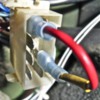
I am illeterate in many things, one of them is my Pantera's electricity. I am triing very hard to understand my Hazard switch, I am also looking at Bill Taylor's (SOBill) diagram nut puzzled as far as understanding the function of all of those wires connected to the switch. Would someone have a description of the utilisation for every wire, so far I understand only the light blue and the light blue/black wire fonctions.
I am having problems with the 4 ways and flashers.

Thanks
Original Post

Replies sorted oldest to newest

Michel,

Try this test. Separate the nylon connector that connects the hazard switch to the car's wiring harness. On the "car" half of the connector, put a jumper wire between the RED and the YELLOW wires (NOT the yellow / black).

Turn the key on to the run position and try the turn signals. This test completely removes the hazard switch from the equation, and allows you to test the turn signal circuit.

John

Attachments

Images (1)
  • Haz_Sw_Jumper
Here ya go, Michel.


Hazard Warning Switch Wiring

Green: To term #30 from fuse #8. This wire is unswitched.

Yellow: From term #49 of the hazard switch to term #49 of the flasher.

Term #30 is only connected to term #49 when the hazard switch is in the ON position.

Red: From fuse #12 to term #15. This wire is switched (ignition switch in the run position)

Term #15 is only connected to term #49 when the hazard switch is in the OFF position.

Pink/Black: From term #49a of the turn signal flasher to term #49a of the hazard switch and to the turn signal switch.

Light Blue/Black: From term L to the turn signal switch, dash indicator light, and the front and rear turn signals on left side of car.

Light Blue: From term R to the turn signal switch, dash indicator light, and the front and rear turn signals on right side of car.

Term L, R, #49a, and the internal light are connected together when the hazard switch is in the ON position. There is NO connection when the hazard switch is in the OFF position.

Yellow/Black: From the instrument light dimmer to term #59d. This feeds the resistor (usually on the back of the hazard switch) that goes to the internal light of the hazard switch.

Black: From term #39 to ground. This is the ground for the switch’s internal light.

Let me know if you have any more questions.

John
Michel,

I would suggest that you start by adding the jumper as I described above. This will allow you to check and troubleshoot all of your turn signal lights, turn signal switch, and flasher, as the hazard switch won't be in the circuit. That way, if there is a problem, you won't have to wonder if the hazard switch might have a problem. You can get everything else working, and then plug the hazard switch back into the system. Then, if something is not working correctly, it would most likely be the hazard switch or the wiring on the back of that switch.

If you don't want to leave the key on during testing/troubleshooting/repairing, place that jumper between the GREEN wire and the YELLOW wire. This will supply UNSWITCHED power to the turn signals. If you do move the jumper to the green wire, make sure to disconnect the battery or remove the jumper if you aren't done when quitting for the evening. It's just a precaution.

Verify first that the green wire is unswitched and the the red wire is switched. I've had one report that the reverse was the case, but I never did hear back from that guy. I don't know if he made a mistake with his voltmeter readings, or a PO changed something, or the "factory" made a change.

John
quote:
OK I have seperated the nylon connector and the jumper installed, turn signal defective, removed turn signal arm and thourougly cleaned it, now turn signals work fine

Great!!! Progress!!! I love it!!

Now that the turn signals are working (on all four corners I presume), remove the jumper and reconnect the nylon connector. Try the turn signals. If everything works, then try the hazard flashers.

If, after connecting the nylon connector, the turn signals don't work, try the jumper again. If the turn signals work again, then the hazard switch is bad.

Keep up the good work and keep us posted.

John
quote:
Originally posted by jb1490:
Here ya go, Michel. Hazard Warning Switch Wiring...
Let me know if you have any more questions.
John


Figured out also with this detail, a faulty hazard switch, replaced with my back up unit, now 4 ways work.

Flasher unit also changed as it was faulty, for a Tridon EP35

All this information is very instructive and thanks to you John.
I understand this section of my Pantera better, now.
quote:
I understand this section of my Pantera better, now.

Excellent!! Hopefully, it will help others to better understand that system in their cars too.

As a reminder to others, if your hazard switch goes bad, you can always separate the two halves of the nylon connector and place a jumper wire between the red and the yellow wires. This will get your turn signals working.

Early car will have a yellow/black wire instead of a yellow wire.

If the connector on your car has a yellow AND a yellow/black wire, only jumper to the the yellow wire.

John
Post
×
×
×
×
Link copied to your clipboard.
×