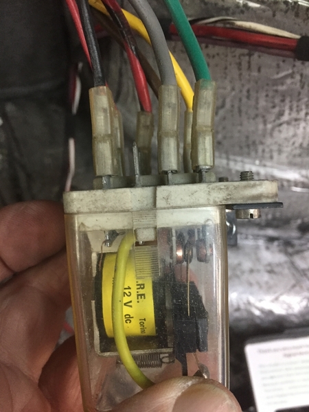
 Last week I had the pleasure of John Buckman assisting me to check the wiring on 2511. In addition to checking the factory harness that somehow survived mostly intact despite the heavy sheet-metal damage, I have completely revamped the engine bay component wiring and added a new panel for headlight relays, electric steering controller and the Jon Haas fan controller.
We did come across a couple of low key issues that were easily corrected, but when testing the headlight motor we found no joy, despite clearly hearing my relays and the OEM relay contacts closing and opening. 🧐
Sure enough, thanks to the clear cover on that large relay, we observed the contacts moving just as they should, but even though the wiring to the motor tested OK and the motor itself had been previously tested, no power appeared to be getting to the motor.
So, we decided to pull the relay and do some bench testing. We observed the contacts appeared somewhat dark from corrosion and with some light polishing using crocus cloth we were able to get continuity through the contacts. 🤗
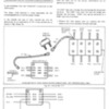
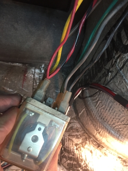
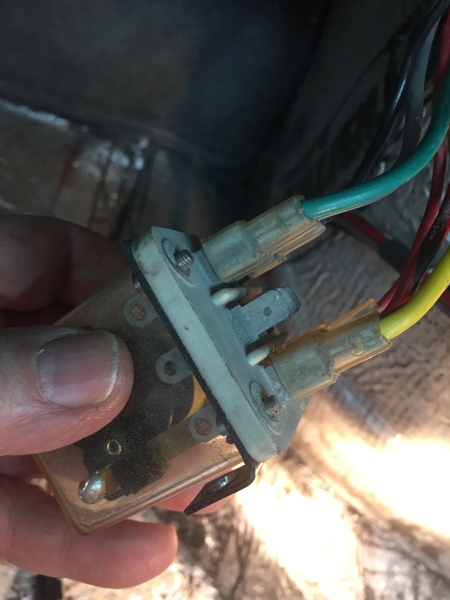
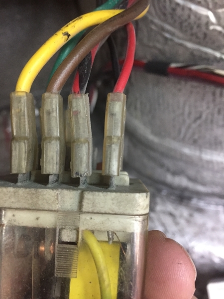
The relay has seven wires going to it, with 11 possible terminals for connection, so before removal I did a series of photographs so everything could correctly go back together.
I found nothing online documenting those connections so I am sharing my photographs here so they can be found by others who find themselves dealing with this relay.
Note the center row of terminals are unused, as is one terminal on one of the outside banks,
2511 is an early car and we know wire colors might change, but this is what I found.
Larry


