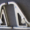
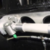
Today has been a “Drop tools & work on Pantera day”.
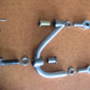
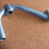
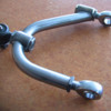
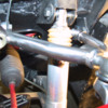
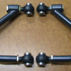
So John & I set about creating some new top front suspension arms to cure the lack of Caster issue.
Nothing new really, plenty of people have made new top arms for the very same reason.
But like everything we do, we had to do it a bit different.
We used some of the parts off the shelf here at Edge for our buggy suspension.
Such as the ¾” UNF rod ends, (chunky) tube inserts & “quick turn” adjuster housings.
The “quick turn” housings are to facilitate adjustment without having to pull the suspension arm apart.
Simply back off the jam nut & turn the adjuster sleeve nut which jacks the rod end in & out.

These adjuster housings are used at the forward chassis mount & at the upright.
At the upright I have used a Ford tie rod end that has a ¾” UNF thread & a 7 degree tapered pin.
(I think they may be the tie rod end from some sort of Ford truck?)
I machined up some little tapered insert sleeves out of stainless steel to adapt the Pantera upright taper to the 7 degree Ford taper.

Because there is a limit to the Ford tie rod ends angle the adjuster housing on the arm is kicked at 7 degrees to allow the suspension to go into full droop without stressing the tapered pin.
Still need to machine some spacers for the ¾” rod ends to suit the chassis mounts reducing down to 12mm.
Ordered some “Seals-It” boots for the ¾” rod ends to keep out the dust & dirt.

I’m hoping for 6 to 7 degrees Caster as the connection point at the upright has been shifted rearward by 10mm, (on top of the existing 2 degrees it currently has).
By adjusting the forward mount in & out it will have a small amount of Caster adjustment, (before it binds up) & the capability at the same time winding in & out the upright mount to set Camber.
Total arm length can be adjuster using all three adjustment points if required.

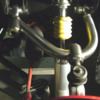
I have bolted in place to test for wheel to body clearance due to the increased Caster & to check it clears the shock at full droop etc,
Tomorrow I plan to re-install with the correct spacers, remove the spring & cycle through its travel & check it functions correctly.

Regards,
Tony.

Attachments

Images (1)
  • Left_top_arm_exploded_copy
Original Post

Replies sorted oldest to newest

As usual, very nice work Tony. I really like the installed adjustability. Just wondering about wheel position in the wheel well. I seem to recall from other posts that you may be in the process of doing some body work. How have you found the 10mm shift in wheel center to affect wheel well fit and tire clearance? I ask because every time I consider addressing front suspension geometry I conclude I would also need to make lower arms (bias upright mount forward 10mm) as well so as to eliminate any rearward biasing of the wheel center…….and yes, with the flares on my car hung about the current position, tire size, and ride height it really is close enough that it would create some clearance issues for me at lock-lock and travel. On a more minor note, it also would noticeably position the wheel off center asthetically, but of course, in many stock Panteras, this is the case anyway. How does it all shake out in your car?

Best,
Kelly
I bolted the arm in place, fitted the wheel to test steering clearance & its got heaps of room.
Thats with a 285/40-15 with a central offset 15x10" rim.
If you had wheels widened outward it could be an issue.
Yes, moving the lower arm attachment point forward would be good to even it out.
To be honest, with the wheels in the straight ahead position, its difficult to pick the top arm modification.
I went for the tubular look as the factory arms, (to my way of thinking) look to chunky & mass produced sheet metal.
The stock shape arms certainly don't do much for the asthetics of a sexy sports car.

Ultimatly I would have prefered to make longer arms, change the upright with more kingpin inclination & less rim offset.
But that will be much further in the future as already I have too many ideas for this car.

Make the arms for sale?
Maybe.
I will want to test first & see what the durability is like, how the rod ends stand up to street use etc.

regards,
Tony
Another test install to make sure the upright ball joint does not bind & to test how much adjustment I have.
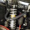
This shot shows the suspension arm pinned in place, spring removed so I can cycle the suspension.
This is in full droop.
Front arm adjuster wound out 12mm, rear rod end only wound out 4mm, (which increases caster + camber).
Adjusts fine without any noticable binding.
Using basic measuring gear it seems to be adjustable by 2 degrees caster on the forward adjuster.

regards,
Tony.

Attachments

Images (1)
  • Full_droop_copy
Thanks Johnny.
I'd like to ask you a question regarding the top arm modifications you have made.
How much did you shift the upper ball joint rearward?
And, when doing so, did you find the lower ball joint getting very close to its maximum angle?

My stock top arms had 6mm shims & i've shifted the ball joint back a further 10mm.
So the ball joint is pushed back a total of 16mm, (like having 16mm shims).
When I assemble I find I'm very close to the lower ball joints maximum rearward angle.
This is with the suspension at full droop.
I haven't popped the boot off of the lower ball joint yet to see if it's housing has a slotted hole surrounding the tapered pin.
(Some ball joints have more angle toward the centre position).

regards,
Tony.
Tony, the upper rear ball joint is the only one of the 3 that has a slot-opening. The others have a circular opening, so no orientation problems up front. Note that adding screw-in zerk grease fittings to the ball joints and tie rod ends is one of the very first mods done to Panteras- back in the early '70s when they were new. Sure adds life to the assemblies and reduces steering effort.
Thanks Guys.
So Bosswrench, that explains the lower joint maxing out if it has a round hole.
When it’s at full droop the lower joint would be at extreme angle in camber & the pin close to the edge of the hole.
As the joint approaches the centre of its position it should have more angle available in caster.

regards,
Tony.
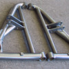
New lower front arms fabricated in tube.
Sway bar mount area is different as I’m running a Schroeder 26” .925” sway bar with splined ends & Aluminium lever arms.
The outer ball joint & shock mount area is much stronger than the original & the cap screw heads are recessed within tubular sockets.
Dimensionally the arms are the same as standard
Original arm weight is 3.25 kg each.
New arms are 3.00 kg each.
So not much weight saved, but a great deal stronger.
Regards,
Tony.

Attachments

Images (1)
  • New_lower_arms_copy
quote:
Originally posted by Edge:
Today has been a “Drop tools & work on Pantera day”.
So John & I set about creating some new top front suspension arms to cure the lack of Caster issue.
Nothing new really, plenty of people have made new top arms for the very same reason.
But like everything we do, we had to do it a bit different.
We used some of the parts off the shelf here at Edge for our buggy suspension.
Such as the ¾” UNF rod ends, (chunky) tube inserts & “quick turn” adjuster housings.
The “quick turn” housings are to facilitate adjustment without having to pull the suspension arm apart.
Simply back off the jam nut & turn the adjuster sleeve nut which jacks the rod end in & out.

These adjuster housings are used at the forward chassis mount & at the upright.
At the upright I have used a Ford tie rod end that has a ¾” UNF thread & a 7 degree tapered pin.
(I think they may be the tie rod end from some sort of Ford truck?)
I machined up some little tapered insert sleeves out of stainless steel to adapt the Pantera upright taper to the 7 degree Ford taper.

Because there is a limit to the Ford tie rod ends angle the adjuster housing on the arm is kicked at 7 degrees to allow the suspension to go into full droop without stressing the tapered pin.
Still need to machine some spacers for the ¾” rod ends to suit the chassis mounts reducing down to 12mm.
Ordered some “Seals-It” boots for the ¾” rod ends to keep out the dust & dirt.

I’m hoping for 6 to 7 degrees Caster as the connection point at the upright has been shifted rearward by 10mm, (on top of the existing 2 degrees it currently has).
By adjusting the forward mount in & out it will have a small amount of Caster adjustment, (before it binds up) & the capability at the same time winding in & out the upright mount to set Camber.
Total arm length can be adjuster using all three adjustment points if required.

I have bolted in place to test for wheel to body clearance due to the increased Caster & to check it clears the shock at full droop etc,
Tomorrow I plan to re-install with the correct spacers, remove the spring & cycle through its travel & check it functions correctly.

Regards,
Tony.


Bumping this thread with a couple questions...I'm getting ready to build some custom arms for my car and I like what you did here. Is there any difference in performance or reliability when using a tie-rod end vs a normal ball joint? Are they the same internally? Would there be any disadvantages to reaming the upright to a 7 degree taper rather than machining an adapter. After measuring and calculating I think the Pantera has about a 5-6 degree taper.
BTW your craftsmanship is awesome.
Thanks, Randy
Randy.
The reason I used a tie rod end rather than a ball joint is that I wanted the ¾” UNF male thread.
This is so I could set it up with our “quick turn” adjuster nuts of the same size.
So to adjust camber I don’t need to pull it apart & rotate the joint.
I just back off the lock nut, turn the adjuster nut & it cranks the top joint in & out.
(Can do a similar thing with the rear pivot point joint & obtain some caster adjustment without having to use shims).
The internal construction of an automotive ball joint & tie rod end is the same.
The only down side to reaming the top of the upright may be the hole may end up too big & the taper pin sits into the hole too far.
Not 100% sure on that as it was a while ago that I did the job.
Yes you’re right; there is at least a 1 degree taper difference.

Here is a picture of my new lower arms.
Dimensionally pretty much the same, just made out of tube & better quality material, as well as being a much stronger construction.
The only real difference is the sway bar mount point as my car is now running a race car type splined bar with alloy lever arms & drop links.

Regards,
Tony.

Attachments

Images (1)
  • New_lower_arms_copy
Here is a picture of my new rack & pinion.
It’s made by Titan in the UK who make race car parts.
(Thanks to Johnny Woods for the recommendation).
Built to my specified dimensions.
Same ratio as the original Pantera, although Titan do have a great range of different rack ratios to choose from.
The reason behind this rack is I’m converting the car to right hand drive & I wanted a rack of better quality.
The distance between the rack ends is 2” shorter which corrects a great deal of the bump steer issues.
I had the tie rods made 1” longer per side to compensate, plus an extra 1” per side to obtain more thread within the tie rod end.
(Panteras don’t have a great deal of thread length inside the tie rod ends which I didn’t feel safe with).
Input shaft is a standard 9/16” 36 spline, so I can get steering uni joints from Flaming River in the USA.
The aluminium plate you see behind the rack is an adapter I made to adpt the slightly different rack dimensions to suit.
So the plate bolts into the chassis at the original rack mount points & then the rack bolts to the plate using the original Pantera saddle clamps.

Regards,
Tony.

Attachments

Images (1)
  • rack_copy
quote:
Originally posted by Edge:
Randy.
The reason I used a tie rod end rather than a ball joint is that I wanted the ¾” UNF male thread.
This is so I could set it up with our “quick turn” adjuster nuts of the same size.
So to adjust camber I don’t need to pull it apart & rotate the joint.
I just back off the lock nut, turn the adjuster nut & it cranks the top joint in & out.
(Can do a similar thing with the rear pivot point joint & obtain some caster adjustment without having to use shims).
The internal construction of an automotive ball joint & tie rod end is the same.
The only down side to reaming the top of the upright may be the hole may end up too big & the taper pin sits into the hole too far.
Not 100% sure on that as it was a while ago that I did the job.
Yes you’re right; there is at least a 1 degree taper difference.

Here is a picture of my new lower arms.
Dimensionally pretty much the same, just made out of tube & better quality material, as well as being a much stronger construction.
The only real difference is the sway bar mount point as my car is now running a race car type splined bar with alloy lever arms & drop links.

Regards,
Tony.


Hi Tony thanks for the reply, that's a great idea to use the tie rod end for adjust ability.....I was just concerned about durability. You might be right about the reaming causing the pin to be a little deeper in the upright. I think it would be a very small amount maybe .020 or so. Do you think that would have an adverse effect on strength or just range of motion? You mentioned in an earlier post making longer arms with an upright that has more KPI to obtain less scrub. I have been considering using the Wilwood Pro Spindle, it has 11 degrees of KPI vs 8 for the Pantera spindle and has a standard taper for ball joints. The Wilwood spindle is very close dimensionally to the Pantera and the steering arms are reversable to help with rack location. I have not purchased wheels yet so this is a clean sheet design as far as offset etc. Your steering rack and lower arms are awesome as well. I am looking into a custom rack also. I really appreciate your thoughts and input as well as others on this forum.

Thanks again, Randy
Longer front arms would enable the front track to be wider & that alone would improve steering.
If you’re running GT4 type front flares then it would also enable the wheels to fill the flares & look correct without having rims widened outward to fill the gap.
Obviously widening the front rims further outward causes more scrub & poor steering.
That's something I refused to do on my car so I stayed with centre offset rims & a GTS size flare.
If the Wilwood upright can be made to have the steering arm at the correct height & length then it’s got to be a vast improvement.
Ultimately drawing up the front suspension in 3D & cycling the suspension through its travel would be the best thing to do.
Regards,
Tony.
Post
×
×
×
×
Link copied to your clipboard.
×