All,
Replies sorted oldest to newest
Larry, Great idea. How well did it work?
Worked great, which is why I have shared it.
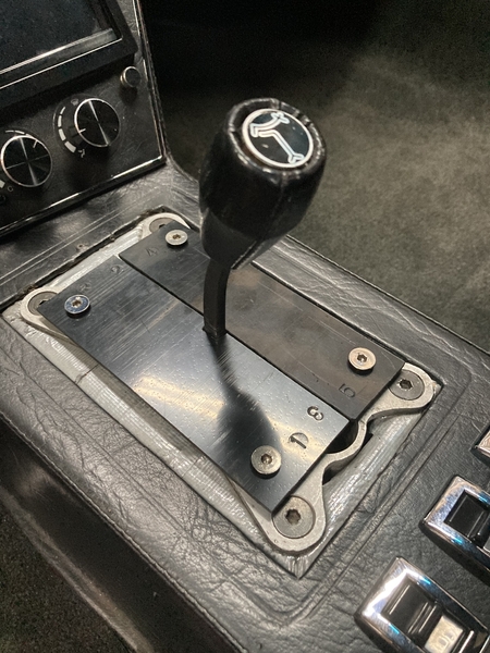
For me the hardest part of adjusting the linkage is the precision required when the turnbuckle jam nuts are tightened. Just a fraction of a degree of unintended rotation of the shift rod can be enough to create shifting difficulties.
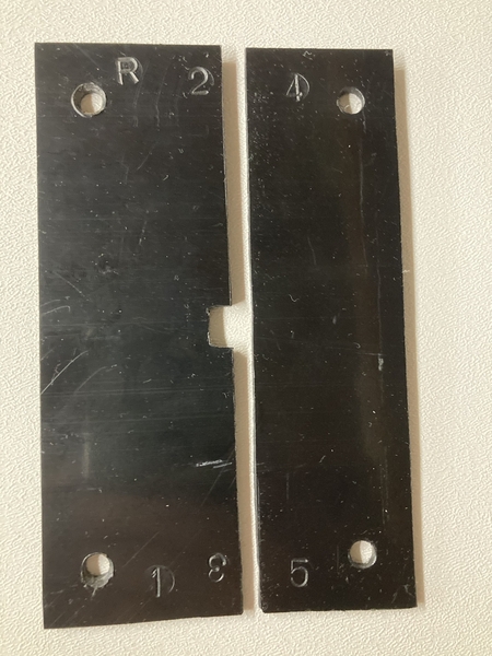
My brackets prevent that unintended rotation, while also centering the shift arm front to rear and left to right
Larry
Larry - looks like the business.
I have previously messed around with wooden wedges with only middling success. I will make up a centering rig like this one .
I am about to pull out the dash and center console ( yet again ....) and am going to get rid of a badly notched gear shift lever with a new one from one from Mike M. A very nice replacement item I must say.
I have never been very happy with the final position of reverse selection which always winds up only 2/3rds up the gate, and reverse always seems to be difficult to select. I don't know if this is common. All the other selection positions are good OK. I will recheck the ZF selector box bolt clearances and penetrations as per suggestions from other posts , and I have already checked the reverse light switch penetration which seems OK .
Any other suggestions welcome!
Larry,
You should find a machinist that can duplicate your device and then you should sell them. Every Pantera owner would buy one.
Larry
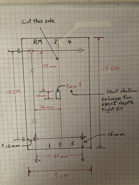
If its not too much trouble also could you post the dimensions of the restraint plate slot position ?
Thanks
3D printers are pretty common now, this seems like something that would be easy made on one.
please post dimensions if you have them, I'll give it a try on my Mangusta
I've made a .obj file to be able to 3d print it. I cannot test it on the car.
Let me know if there is something I need to redraw.
Edit: I do not know if anybody can use the file like this. Any ideas?
Attachments
It's printing on my 3d printer as I type...
are the Mangusta & Pantera mounting holes the same?
MH
Hi Brickdrifter - would you be able to export in STL (stereolithography) format and post it?
It may be a file export option you have ?
Thanks
I already converted it, give this one a try
MH
Attachments
Thanks for posting the dimensioned sketch larry!
Good Day! Thanks all for sharing, this is a great tool. I have already downloaded the sketch and the STL ....hopefully I can use the gauge during the re-build this fall ![]() .
.
Larry, that's a great idea - thank you for sharing!!
Same dimensions will work for a Mangusta (120 x 65mm pattern) - regards, Nate
I deleted my long post about my ordering a 3D printed one from Protolabs yesterday. As an update, they e-mailed me today that basically said because it involves 2 pieces, the file would have to somehow be re-submitted as maybe 2 .stl files, then re-quoted, and I assume the cost would go up some. OR maybe the 2 part plans could be re-done as 1 part, then you could make the longitudinal cut basically down the middle with a bandsaw or something yourself. But in my case, I learned in the meantime that I likely am a spline off at the shifter box at the ZF and "should" be able to get back to getting all gears as before my ZF was rebuilt (thanks Ron!). So at this point I plan to let my order just cancel for now, and I will pursue it from various angles later when I have more time.
@buttondoor posted:I deleted my long post about my ordering a 3D printed one from Protolabs yesterday. As an update, they e-mailed me today that basically said because it involves 2 pieces, the file would have to somehow be re-submitted as maybe 2 .stl files, then re-quoted, and I assume the cost would go up some. OR maybe the 2 part plans could be re-done as 1 part, then you could make the longitudinal cut basically down the middle with a bandsaw or something yourself. But in my case, I learned in the meantime that I likely am a spline off at the shifter box at the ZF and "should" be able to get back to getting all gears as before my ZF was rebuilt (thanks Ron!). So at this point I plan to let my order just cancel for now, and I will pursue it from various angles later when I have more time.
Have you considered printing it out on 8 1/2 x 11 and mounting the paper to a thin piece of plywood or acrylic and cutting it out with a jig saw or band saw? I have a laser etcher that I could burn it into a thin sheet of wood for you... My laser probably won't cut the wood, but it could give you a good pattern to work from... If you want to print it one paper i can make you a pdf that you just print it 100% scale.
MH
As the original poster, let me jump back in to the thread.
I want to stress this is not a high-tech, precision-machined tool. If your version varies by a millimeter here or there it should still perform its basic function. It is a very basic approach that solves the need to properly locate the shift lever when adjusting the ZF.
I cringed when I read the quoted cost for your 3-D printed version. I’m glad you have taken a different approach. But for others following this thread, please do not overthink this.
Larry
One sentence in the OP mentioned a "badly notched gear shift lever". The stock chrome plated gearshift guide's edges are MUCH harder than the mild steel gearshift stick, and road vibration saws clearance from the softer shift stick. I replaced my '72's chromed gearshift guide with an aluminum duplicate, and filled the worn notch in the stick with stainless steel TIG weld, then filed the weld flush and polished it- no replating needed. Cannot tell it's ever been worked on.
BEWARE- undocumented mfg change! I mentioned my successful rework to a friend with an '87 GT5-S, and when a local shop tried to duplicate my work, we found that his late stick was built differently. Seems his stock '87 gearstick was a stack of thin sheet metal pieces edge-brazed and plated, not a one-piece forging like the Ford-era stick. When they tried to fill his worn notch with TIG-welded stainless steel, the whole gearstick fell apart. A used '71 gearstick fit perfectly in his '87, but was extremely expensive. Be advised!


