OK, first off....the tach is working! ...and so is everything else! What a concept!
What I don't have, is a clear diagram of what is in the car.....simply because it has morphed and "been fixed" and all the old wires are still all over hell and back......
What I have been dealt: 74 car. MSD 6AL control module...not digital as far as I can tell...(no switch dial thingys..... AND a 8920 Tach Adapter.
This car has had a points distributor, a Duraspark Distributor, and now is some sort of MSD or something....WITH a Pertronix module in it.
The 6AL diagram instruction book comes with a diagram of the 6AL with DuraSpark dist module OR a Pertronix....but no integration of the 8920 Adapter.
So, I still have what appear to be the magnetic pick up leads still connected, plus the new Pertronix connected....and who knows what else.
I have (you'll love this!) a junction block of sorts for the switched +12V power source, hanging unprotected from shortage....tie-wrapped to a water hose..... I think I'll rummage thru the wife's Tupperware drawer to see if I can find a small container to put this thing in.....it is so bad it needs to be preserved...... Ok, not really. But I do need to find either a 1-in spade and many spades out sort of junction block.... or just a buttload of heat resistant tape..... Sheesh!
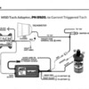
On page 165 of a doc that I found on MSD's site "Catalog_wiring_diagrams.pdf" (not posting the entire thing here, but I will attach part of page 165 that pertains to a "Current Triggered Tach" which I believe is the type we have in our cars.
We do not have a "Voltage Triggered Tach" as far as I know....diagram shows typical tach with one wire to ground and one wire to switched 12V and one "trigger wire"....
So back to current triggered.... two leads....one to switched +12V adn the other to the RED wire of the tach adapter. Good enuf.
MSD 6AL has 8 connections.
MSD 8920 Tach Adapter has 4 wires.
On the diagram,(6AL box) no distributor is indicated...... BUT there is a lead "Magnetic Pickup" which is a pair of wires, Violet and Green. These would normally connect directly to a DuraSpark dist module with same colors I believe. Or any other dist with a mag triger of some sorts........
The white wire out of the 6AL is what normally would connect to a points ignition distributor. Single wire thing. IF DuraSpark Magnetic Pickup wires are used, this White wire is not used. (I believe it can be used as a security thing by putting switch to ground on it!) If this white wire is being used, then the Violet/Green wires are left open. (one of the wires can also be used for a security switch....but need to look it up...which one!)
***Pertronix Hookup: 6AL White wire connects to black lead of Pertronix module. Red Pertronix connects to +12V switched "original coil wire" from ignition switch. (Green and Violet mag trigger wires are not used!)
The TACH output connector (which is a "no wire" connector on the 6AL box is connected to the 8920 Tach Adapter via a white wire from/to the Tach adapter.
The Red wire from the Tach adapter is shown as connecting to the tach.....and here is where it gets fuzzy!!!!!
Their TACH in the drawing has two wires...one connects to the Switched +12V that originally also fed the original coil wire (unknown color!) this would be the resistance wire?????)...from the ignition switch.
The "other TACH wire" (also unknown color) is where the RED 8920TA wire is supposed to connect in the Pantera scheme of things.
I have no idea yet....what the colors of these two TACH wires are in the Pantera...but one of them should be connected from the switch to the tach...then out to the coil (original coil + wire)...so it should still be connected behind the dash somewhere....and probably don't need to worry about it....but for connecting the RED 6AL wire it should be known!
The Red wire on the 6AL box is for switched +12V ......envision my block of wires growing.... BUT the brain asks me if this should be FULL 12V switched....or is the voltage after the resistance wire OK? (ie reusing the coil wire connection in the engine comp.) Diagram is not clear here.
Orange and black wires (6AL box) go to + and - of coil respectively.
(6AL) Heavy Red and Black go to unswitched +12V (direct to battery) and Ground respectively.
On the 8920 Adapter, black wire is ground, and finally the Violet wire there is not used!
I think that covers all of the wiring from the two boxes and their interconnection.
NB: I need to check 8920 TA Violet wire and see if it really is not connected.....
So, the boild down of all of this, for future undertakers of this task!!
1) does the 6AL need a full +12V switched at the red wire? Or is "what you get" at end of resistance wire (at coil) good enuf?
2) where does the 8920TA Red wire connect to? (Where is the "other side" of the tach supposed to be?)
The rest is extremely straight forward...."almost" plug-n-play!
OK my brain is hurting......see JPG file of the diagram. Hopefully it will display well. Otherwise I have a PDF of the same diagram but not sure if I can attach it in same manner.....practice practice....!
Ciao!
Steeve
Attachments
Original Post


