Photo in attachment
It was connected to a solid purple wire in the main harness under the dash
Bought a replacement switch and it does not have this extra connection
Any help would be appreciated - Thank you
Replies sorted oldest to newest
"30" is a DIN number that essentially means "battery"...This is the connection to the 12v source that is then switched for whatever.
@doobwaa posted:Does anyone know what the single plug is for on the Turn Signal Switch Wiring ( white wire w/ blue stripe )
Photo in attachment
It was connected to a solid purple wire in the main harness under the dash
Bought a replacement switch and it does not have this extra connection
Any help would be appreciated - Thank you
That extra wire is for the drivers lights on GTS , GT5-S and GT5 Pantera's
those cars have extra drivers lights., GTS have them mounted under the front bumpers, GT5-S and GT5 into the front spoiler.
you can give a flash while the headlights are off
while the early Pantera and the new replacemenmts switches dont have this function , the GTS, GT5-S and GT5 has this extra function, pulling into the backward is possible, by the early Pantera's and the later replacements it's not.
Simon
A couple of years ago, I purchased a new reproduction turn signal switch from the capri vendor teamblitz. It does incorporate the terminals necessary for the flash to pass function.
I am using that function to control two LED driving lights I installed in redesigned turn signal pods.
Larry
So in other words, on car #2034 I don’t need to worry that this terminal is not attached to any leads?
@lf-tp2511 posted:
Larry,
that looks very good , wher have you purchase that front spoiler ?
I was looking for 1 or 2 .
regards
Simon
@hej posted:So in other words, on car #2034 I don’t need to worry that this terminal is not attached to any leads?
yes , I think so , if everything is works as suspect , it dont have a function.but sometimes they switch colors on the replacement switches, easy to find out whit the old switch in hand .
you can chance the pins from the connector..
Simon
Simon, if I’m not mistaken, Larry’s front spoiler is from Pantera Performance in Colorado. I believe it’s made from urethane or some other type of flexible material.
Yes, spoiler is from Dennis. It is made of ABS black plastic with a pebble finish. He also offers it in fiberglass.
cost a few years ago was $125. I do not know if he currently has them in stock.
Larry
I’m calling him shortly. I’ll find out if they’re in stock and report back.
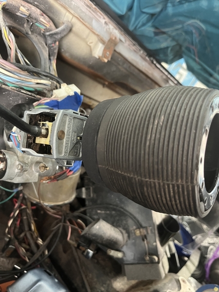
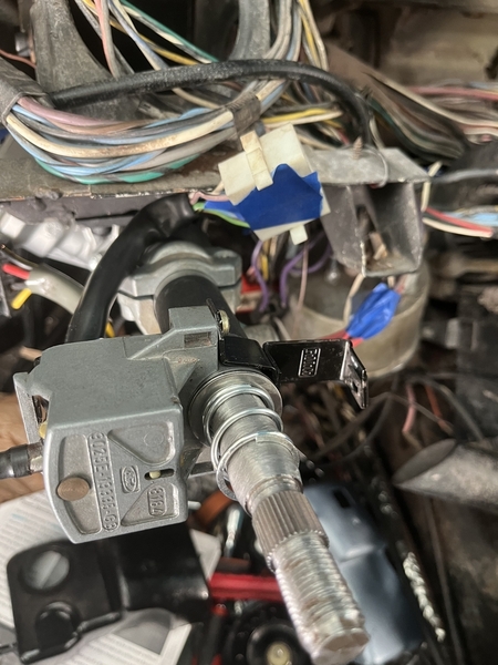
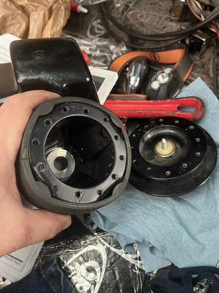
Another figment question. Reinstalling the turn signal / blinker stalk. Located correctly on the column (shroud holes all match up), but the cam fitting on the steering wheel hub (quick release version) comes no where near deep enough on the splines to engage the cancellation tab on the stalk. 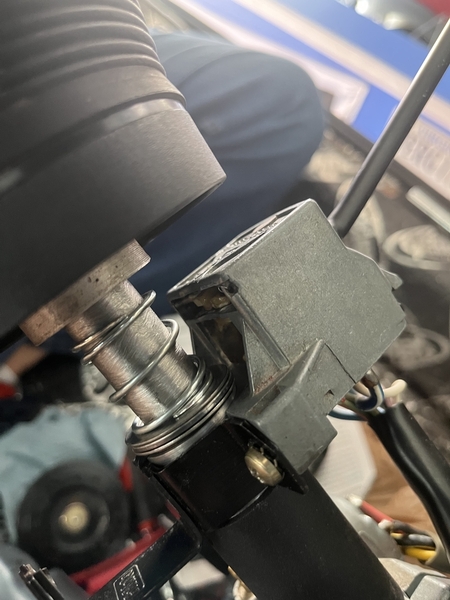
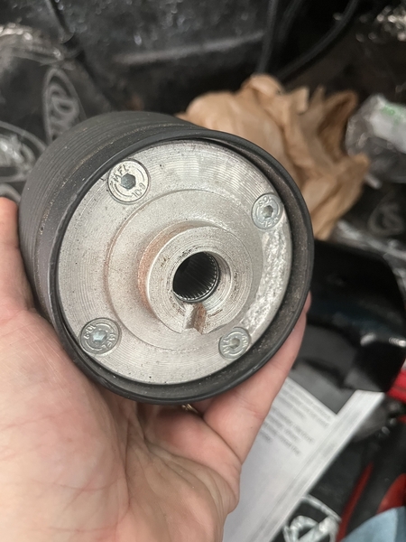
@hej posted:
You need a Cam turn signal canceling Part nr. 03006A Wilkinson .
original they are red.
Simon
@lf-tp2511 posted:Yes, spoiler is from Dennis. It is made of ABS black plastic with a pebble finish. He also offers it in fiberglass.
cost a few years ago was $125. I do not know if he currently has them in stock.
Larry
Some time ago I ask Adam Quella, they had them not in stock.
Simon
Dennis does not have the ABS spoiler in stock. Adam told me several months ago their vendor "lost" their mold for it and screwed them. Adam was trying to figure out where to go from there. I have not asked him lately.
Regarding the red cam extender, found it. Multiple years of varying states of disassembly will scatter stuff about. Thanks again.
Can be massa/ground , but not used .
Simon


 That’s interesting. OK here’s one more question and this may be a little difficult because it looks like there’s been several people who have gone through this wiring loom and added all kinds of nonsense through the years. As I’m putting the heater box and the dash back together, after finishing the assembly of the power steering unit, I came across an absolute jumble of wires that were attached back on them selves in a lasso a bunch of tangled copper wraps between them. One is a thick red cable and the other is a thick black cable near the steering column. Both of these seem to run back behind the dash, under the passenger side, rocker panel, and up behind the passenger where they seem to go to either side of the starter solenoid. The black wire branches off into two pink wires that go to the fuse box. With this mess disassembled, there is no power to anything, when I simply touch the two main cables, the red and the black below back together. Everything works like it supposed to. Clearly, this is the connection between right and left as far as the circuits concerned, but I don’t know why these would run all the way up to the cockpit you’re the driver.
Those two wires (red and black) originally went to the ammeter. The red wire comes from the battery.
John
So I assume then I can just wire them together and be done with it?
yes , it's even better than use the AMP gauge in series .
this eliminate transition resistance from the (small) connectors/gauge.
Simon
@hej posted:So I assume then I can just wire them together and be done with it?
Those wires carry a very high amperage load. They must be firmly connected. Best approach would be to crimp on two ring terminals and firmly bolt them together, then heavily insulate the connection with electrical, tape, and/or heat shrink tubing.
Larry
@hej posted:
...I believe that 'Spade Tang' is for a Grounding Wire, to Be Sure the Housing IS Grounded for the 'Sensor/Switch', to Operate the 'Key Left In Ignition' Buzzer. I Imagine the Buzzer sounds when the Drivers' Door is opened...Not sure. Corrections Welcome!
MJ