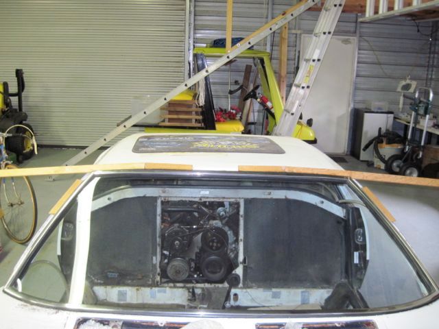
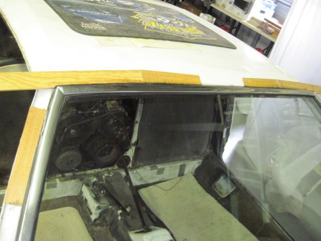
quote:
Originally posted by UFO-LOW:..I decided I should measure....Declare victory and move on!


I think you will appreciate my buisness motto signiture line as it is very appropeate for your work

“when you can measure what
you are speaking about, …
you know something about it;
but when you cannot measure it, …
your knowledge is of a meagre
and unsatisfactory kind…” Lord Kelvin 1883
You betcha - I was certainly aware that it was possible I could do some expensive damage. Like when I repaired the pimple dent on the deck lid, I put the O/A torch to it, and that deck lid skin bowed up about 2 inches; that got my attention. Thankfully, it returned to shape when it cooled.

Anyway, on to the next task, fixing the rust and damage at the front. This required some more measuring; to calculate the radius of curve. I measured the piece before taking it apart so I could make the repair pieces to fit.

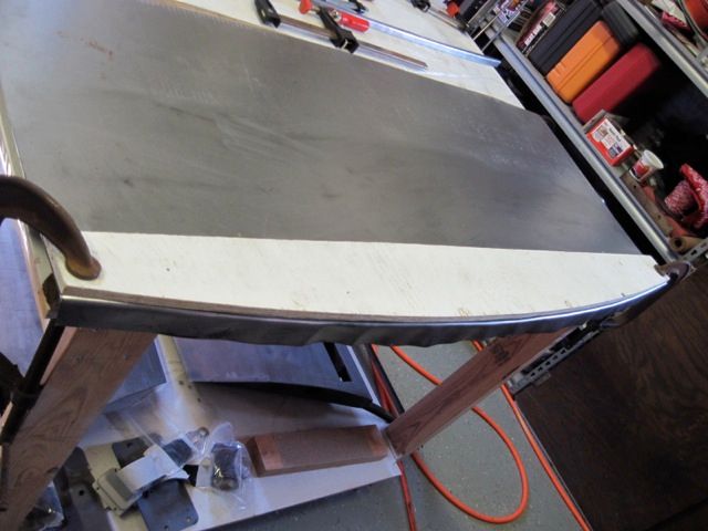
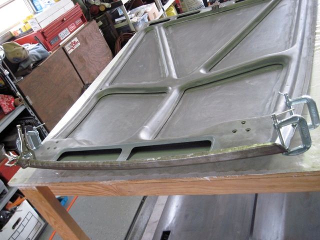
This is just a stiff, straight piece of aluminum channel, held with some screws in the outer most hinge bolt holes. The only purpose is for a reference to measure from:
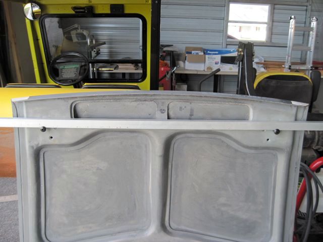


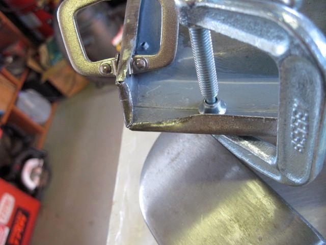
Now to take a measurement at the outer edge:
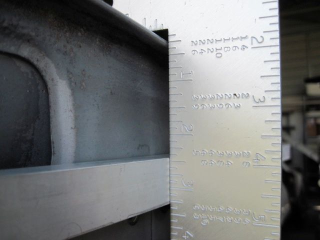


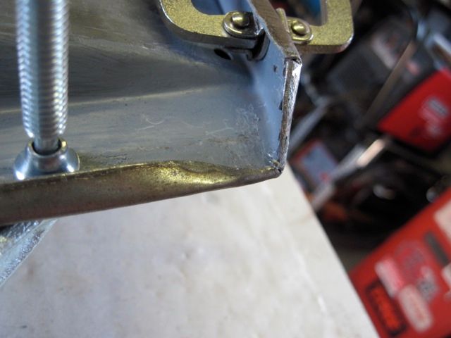
and one in the middle:
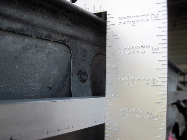


Now I won't bore you with the math, but if anyone is interested I can give you a link to find the formula on the 'net. Mine worked out to be 123.5 inches of radius (just over 10 feet).

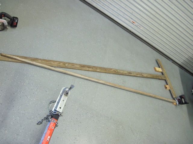
This is a pic of how I improvised cutting such a radius with my saber saw. I am cutting wood here, not metal. Two pieces were cut to use as a guide for cutting the metal, and as a buck for bending it.


As I am looking at this, I see I can use the frame to hide the repair from the inside, so I don't have to do any cosmetic work there. Not having X-ray vision, however, I have to locate it on the outside. Here some masking tape is laid in and marked:
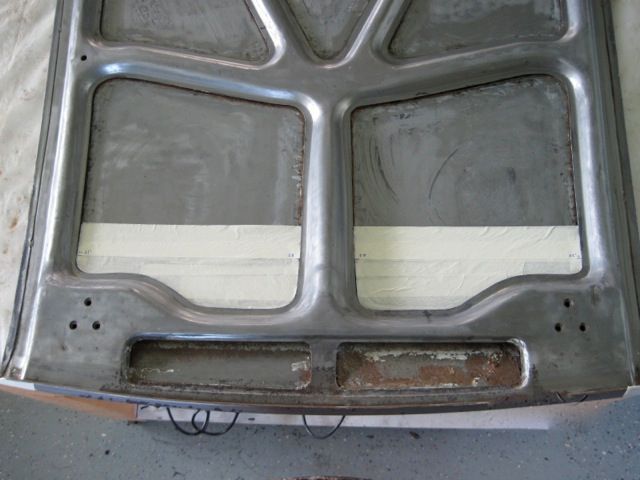


With help of the reference marks I made earlier, I marked the frame on the outside.
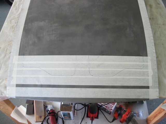


I moved the cut line about 1 1/2 inches forward of this, to be sure it would be hidden by the frame, and cut the metal with the die grinder:
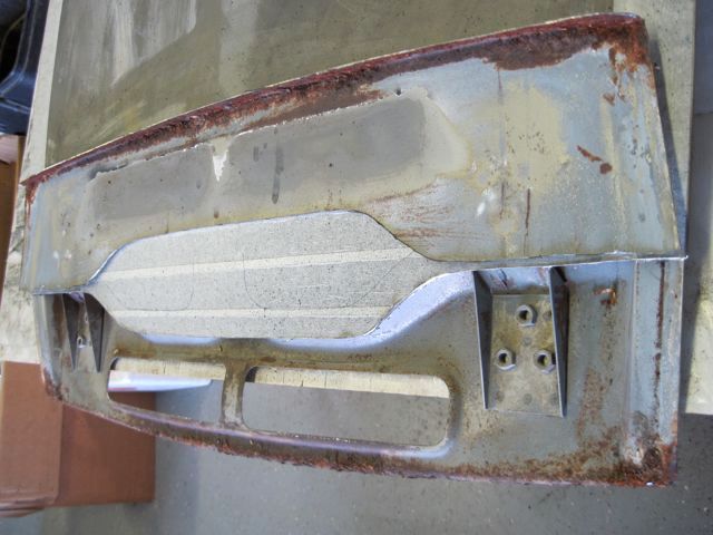


Having never seen inside, I had no idea what was just behind the skin, so that is why I did not use the plasma cutter for this.

I can see now that the leading edge of the frame will need to be replaced too. This is a complex piece, more so than the outer skin. I did not think I could create the stamped contours, so I decided to leave as much of it as possible intact.

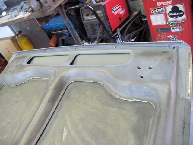
Here I've cut off the rusty lip, leaving about 2 inches at each end (just out of view in this pic):
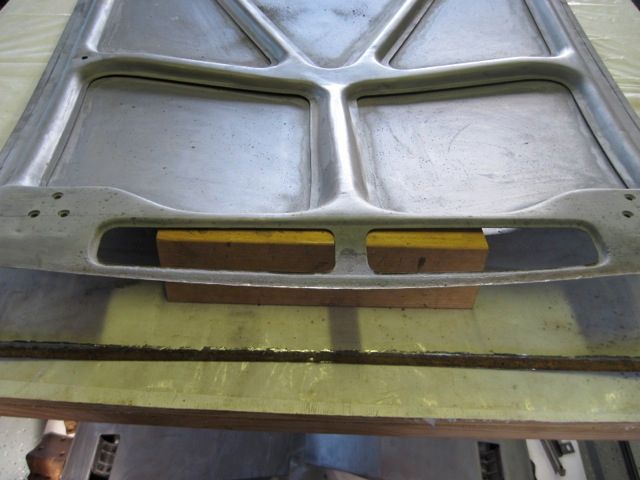


The remaining metal is cleaned up and treated with ospho, but it is still rust pitted, so I do not think I can weld to it. I decide to put on the repair piece with panel bond epoxy and a few pop rivets.

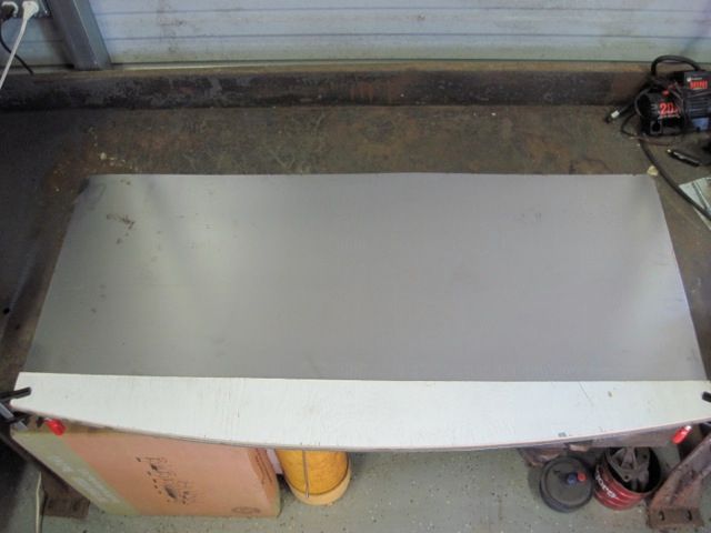
Now to start on the repair pieces. I've learned to use a wood guide with the plasma cutter; it holds the tip just the right distance off the metal, and gives a smooth fast cut.


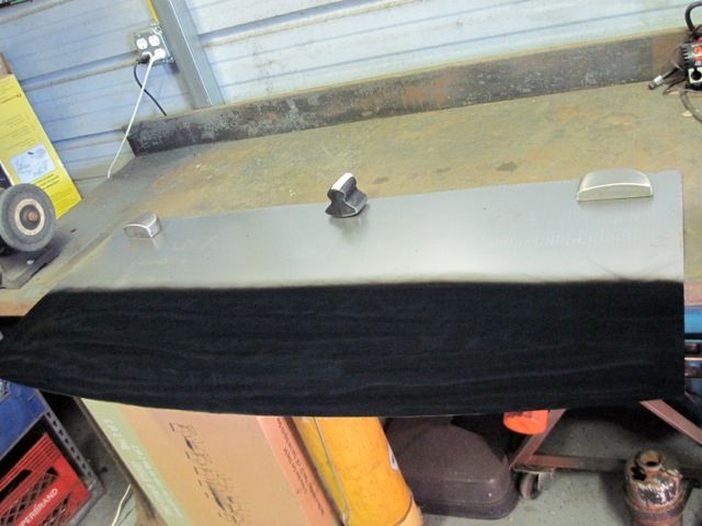
Here is the soot from annealing the metal before shaping it:


Clamping the new metal between the wooden bucks I made earlier, I bend the lip on the frame repair piece:
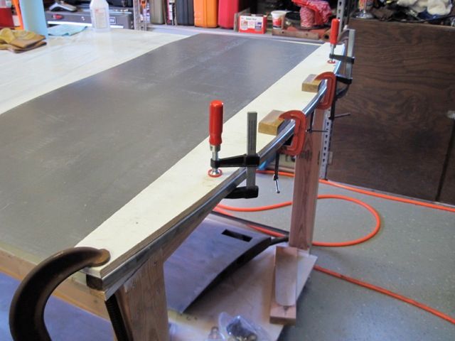


One more pass with the plasma cutter, and I have the frame lip repair piece in rough form:
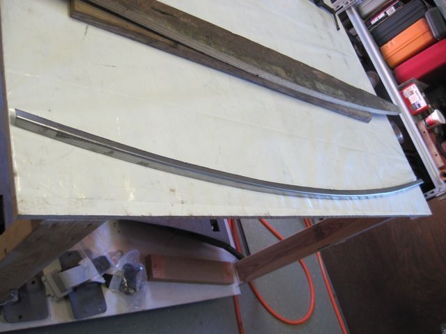


I have to shorten it, and use the shrinker to form the compound curve to match the remaining frame material. Here it is being bonded in place:
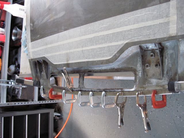


I also added some pop rivets, and hammered the leading edge lip over some more, as it has more than a 90 degree bend, but I could not have got it into the shrinker jaws had I done that first; so I had to do it after installation.

Here I use the same wooden bucks to bend the lip of the skin repair piece:
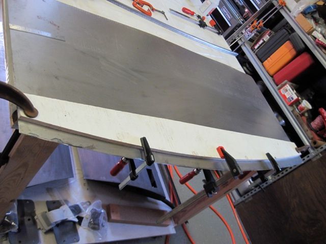


Notice I left more material, as this has to crimp over the lip of the frame I just installed. Also notice how the metal buckles some when bent over. No problem; the shrinker will fix this when I put the proper crown on the piece.

I made a wooden fence to match the cut on the skin, and used it to guide the plasma cutter:
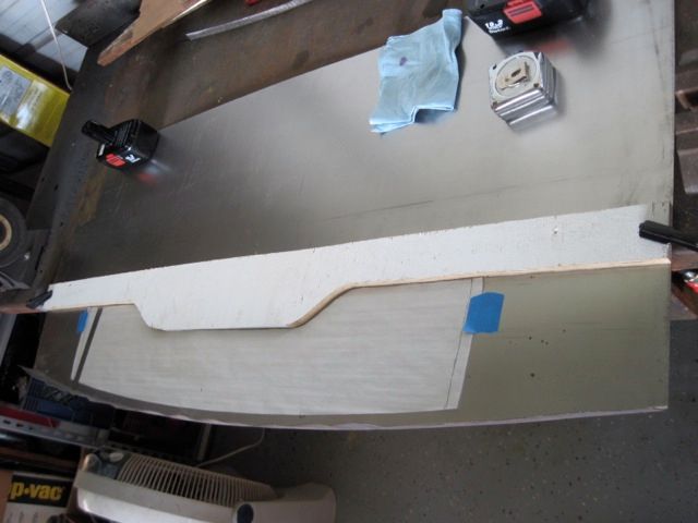


I cut off some of the excess width, and shrank the lip to put in the necessary crown curve. Now it is starting to take shape:
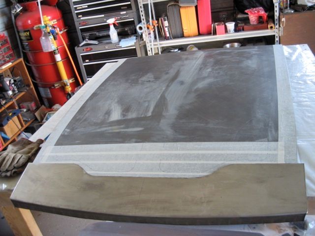


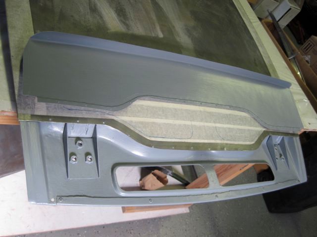
Here I'm just about ready to put the patch on. You can see how the frame repair came out, and I put in a couple of small drain holes. It is all cleaned up and epoxy primed on the inside. The overlap is flanged and drilled for sheet metal screws that will hold it together for welding:


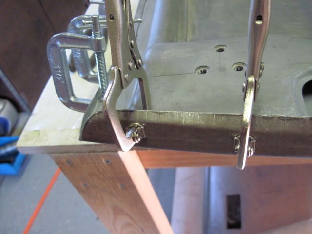
Here it is screwed in place, and I am starting to bend the edge flanges over:
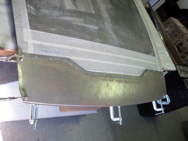


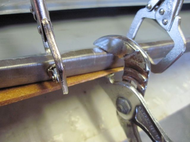
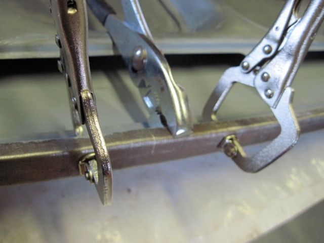
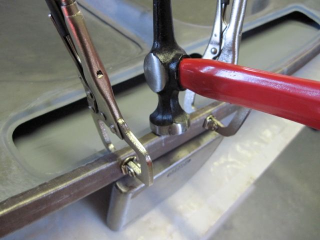
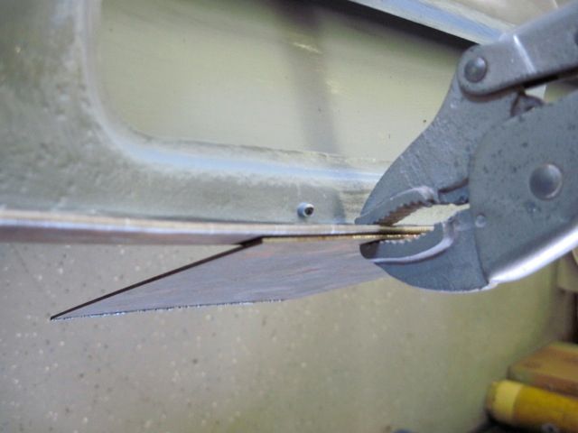
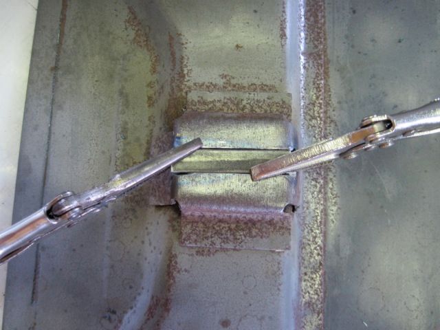
Here is a series of details of bending and crimping the edge flanges:


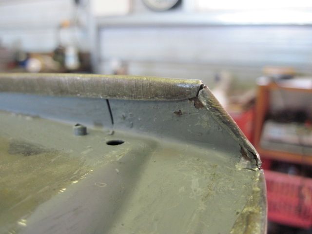
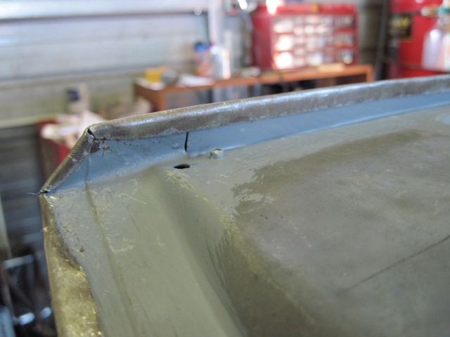
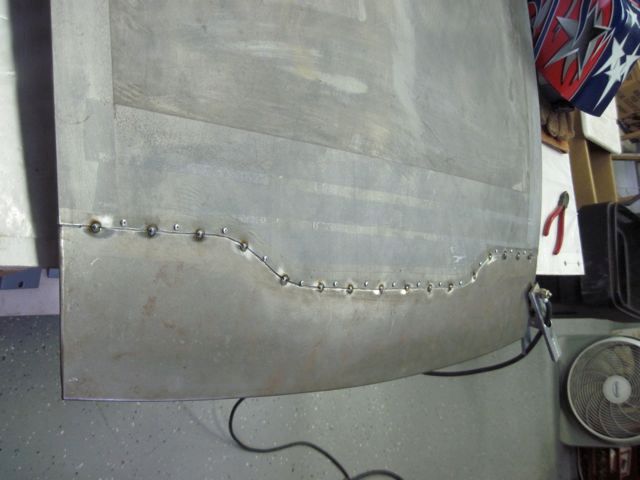
After finishing the edges, I spot welded along the joining line, removed the screws, and welded the holes shut:


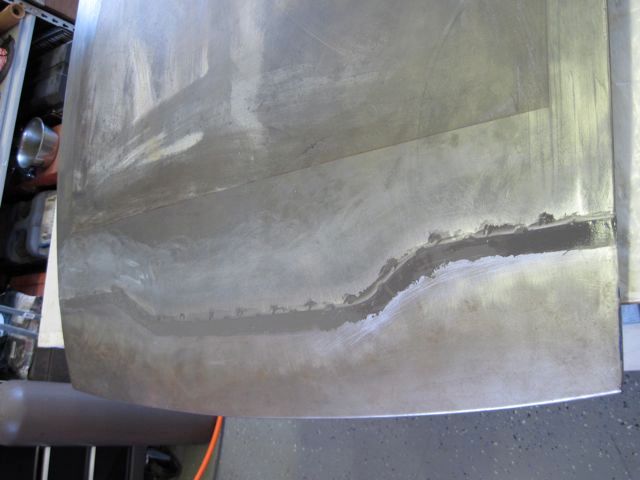
The depth of the flange crimp my tool makes is not exactly the same as the metal thickness, so there is a very small step. I filled this and some of the weld divots with epoxy:


WHEW!
Last edited by ufo-low
Yes, JFB has it.

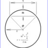
Can be reduced to

r = (c squared / 8m) + (m / 2)

Anders, I think from over head view, the radius of the front cross member should be the same as the front of the lid, or it would not look correct. From front view, I think it is flat.
I will take some measurements and pictures tomorrow for you. Rodney
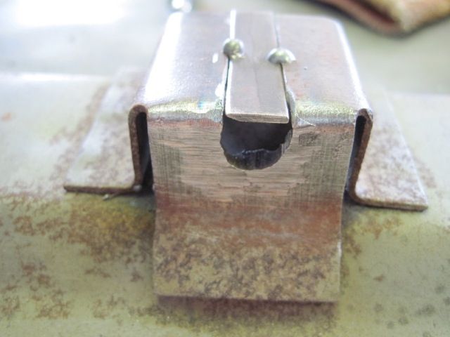
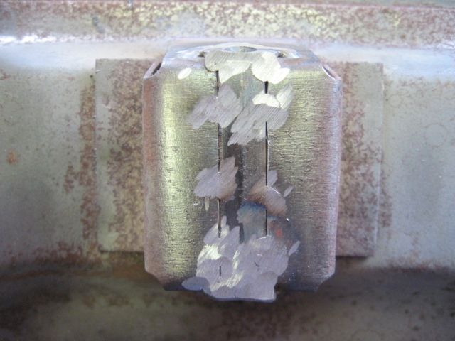
Here is an example of one of those dinky little jobs that turns into a real time eater. I wanted a new stainless steel latch pin for the trunk lid.

The original was worn and rust pitted;


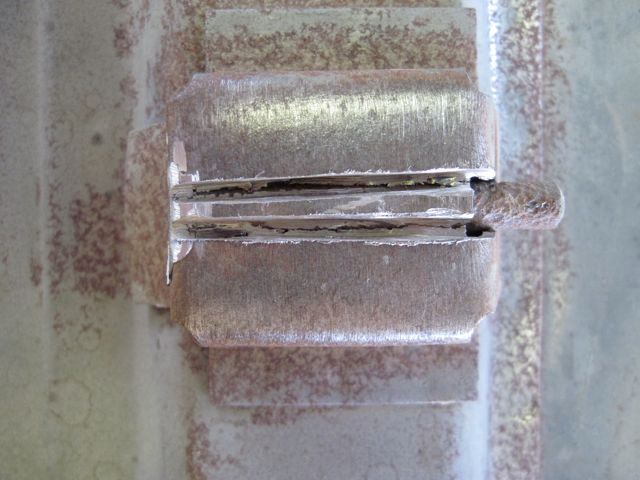
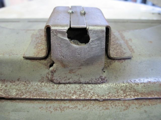
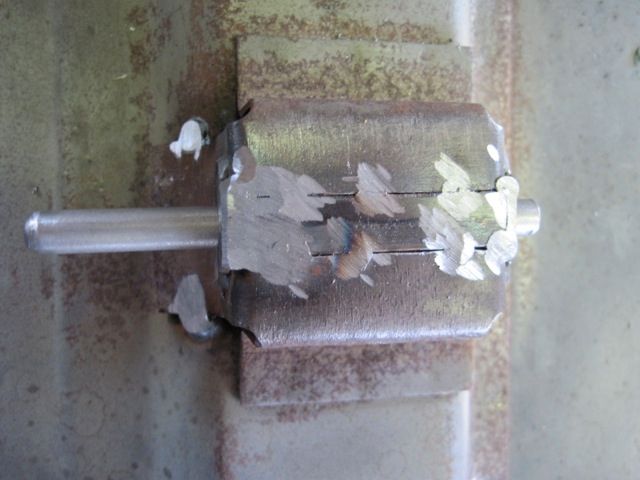
I did not take a picture until I had already started to remove the old one. Now if you give a quick look, the pin is welded to a sub-bracket, which is welded to the trunk lid frame. It appears that the pin is spot welded to the sub-bracket at the ends, which it is, and grinding those welds off will free the pin. No, it won't. The pin is welded to the sub-bracket on the inside too. I had to slice through the sub-bracket along the length of the pin to remove it;


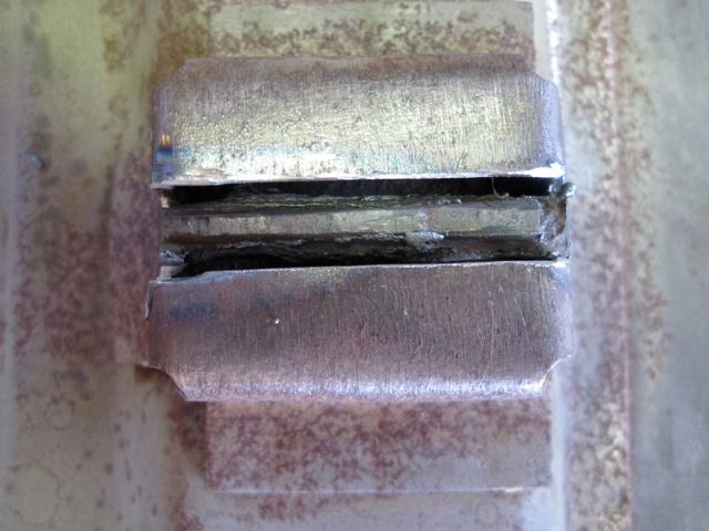
Next I tacked in a strip of metal to fill the piece I had to cut out;


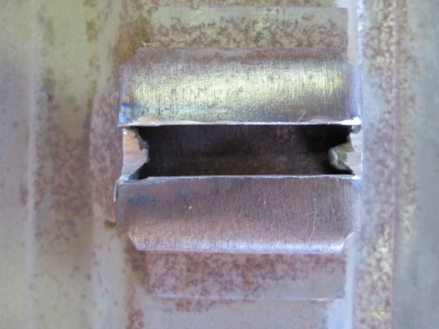
This left the ends pretty butchered up;


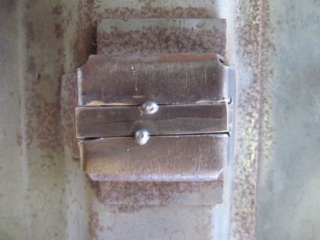
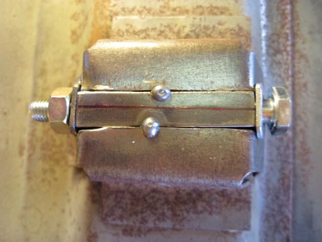
Two small stainless flat washers were fitted to the ends and welded in place;


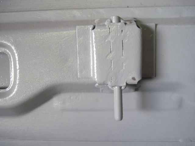
A few more spot welds to strengthen the whole affair, and the new pin can be welded in place;


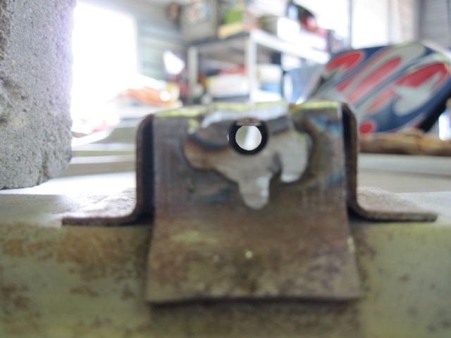
After primer, it looks OK, not great;


It may have occurred to you, as it surely has to me, it might have been easier to cut the old sub-bracket off, pin and all, and make a whole new one. Had I known that the pin was welded on the inside, I probably would have done that.
Last edited by ufo-low
quote:
Now, being an engineer, I wanted to use a precise method to straighten the trunk lid. So ... I got up on the table, put my foot on the high spot, and stood my weight on it until I felt it "give". I was really afraid that I had made matters worse, but I shimmed the corners and took the measurements again

Brilliant! Love it!
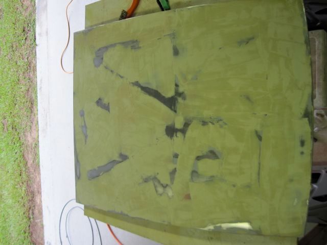
Alright - back to work. To finish (for now) the trunk lid with primer and base body work.

Here is the piece just after the first coat of primer:


Next a thin all-over layer of body filler:


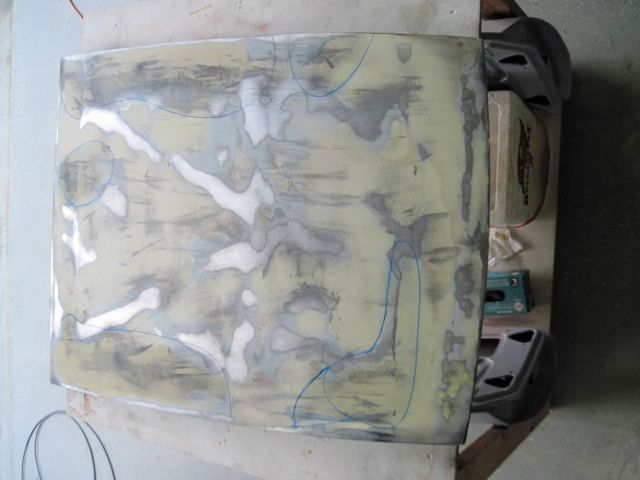
The first sand off reveals the low areas. Marker shows me where to go easier on the sanding to achieve a little build up:


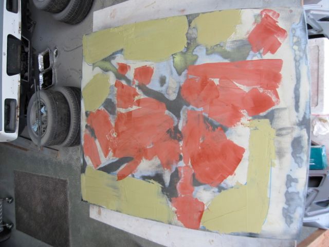
More filler in the serious spots, and some glaze putty for minor smoothing:


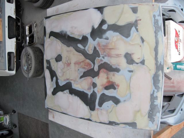
The next round of sanding gets it closer. Funny how you can clearly see where the frame is, even though it does not touch the skin in most places.


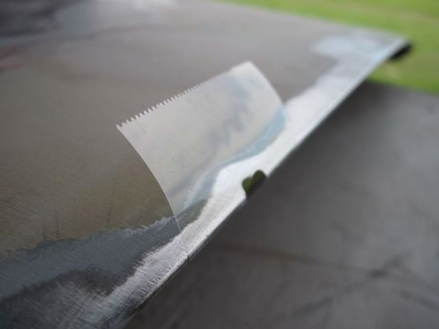
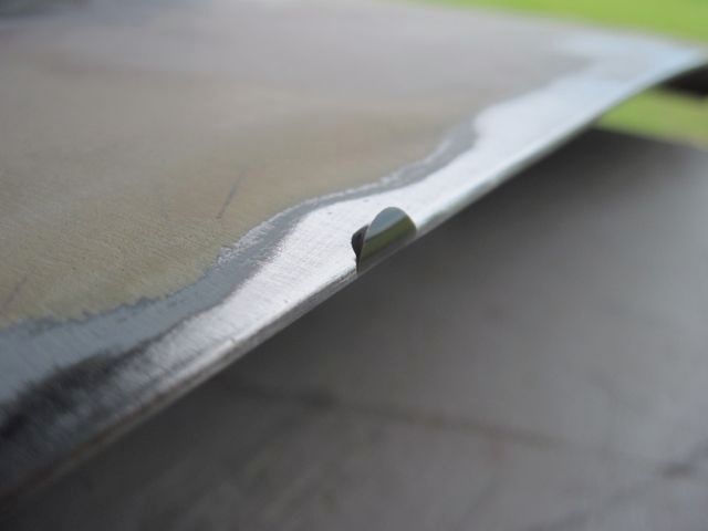
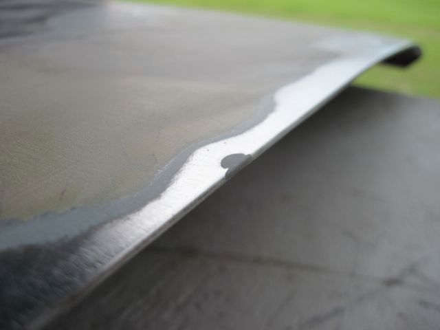
Here I found a "nick" in the edge. Too late to be welding on it, and too big for just filler. I put a dab of JB Weld in it, and put a piece of tape around it to hold it while it set up:


Remove the tape:


and sand smooth:


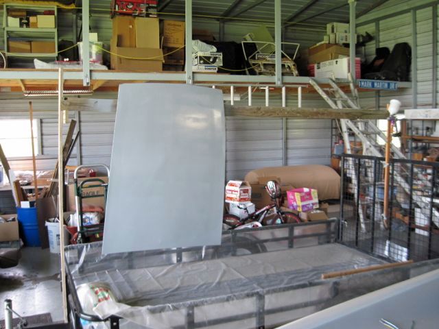
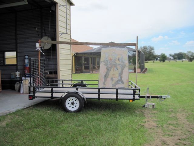
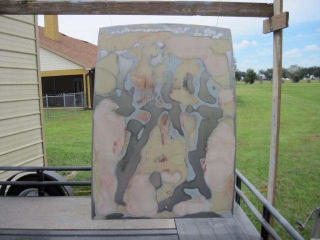
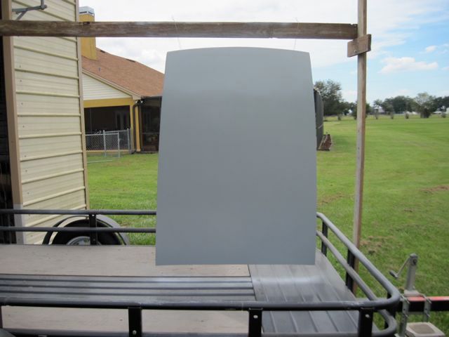
Here is my new painting solution. I've set up a temporary support frame on my trailer. I hang the piece with wires, and roll the trailer outside. Then I can spray all around the piece without moving or touching it. When finished, I clean up the spray gear, and push the trailer back inside out of the weather.


Before:


and after:

Last edited by ufo-low
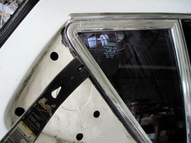
Here is a tip I think others may find useful. I've heard it said that the pantera's glass is easy to remove, yet I've also heard many reports of breaking glass while removing it. The issue I found was the gaskets, having not moved for 44 years, are quite stiff.

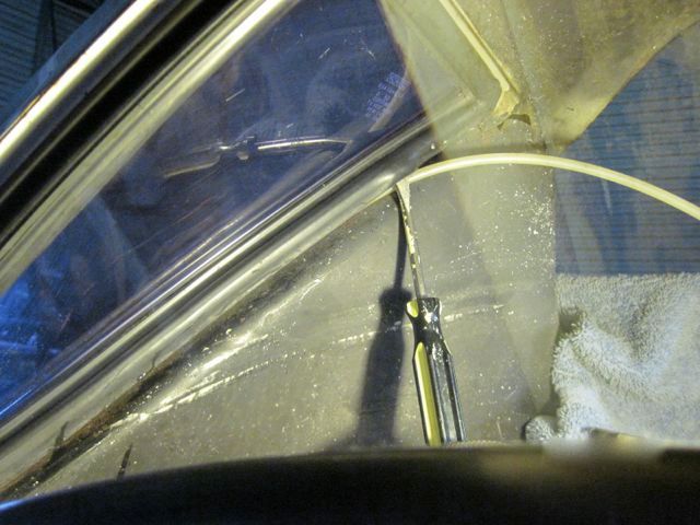
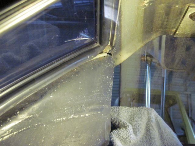
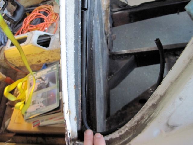
I used some 1/4 inch plastic poly water line, and tucked it under the lip of the gasket on the inside of the glass. Here I'm doing a rear quarter window:


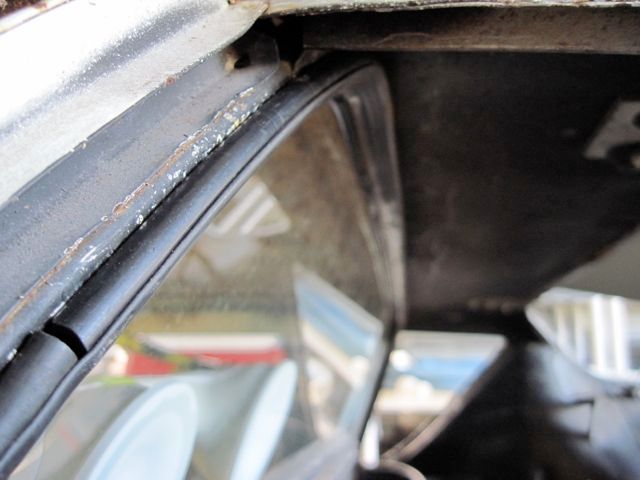
Tuck the plastic line in all around the window, except the corners. This flexes the gasket out a bit, and gives it a ramp like surface to slide on. Spray WD40 or similar in there too:


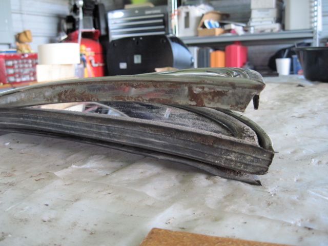
Then pry the glass, trim, and gasket out all together. Use as wide a tool as you can, and get under the gasket. Do not pry on the trim, it will bend easily.


Do NOT try to remove the trim alone. You will see why when you get it apart. The trim has a retention flange on the back, which fits into a groove in the gasket. The gasket traps the flange when installed in the car.

Last edited by ufo-low
Here is the same method on the cockpit back glass, with a new trick.

Pry up the lip of the gasket and tuck the plastic tube under. Spray lube in here also:


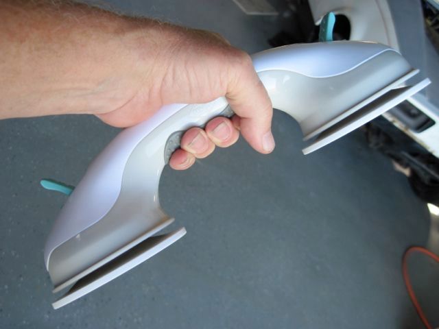
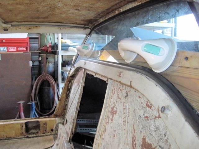
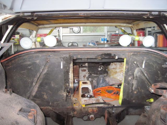
These handles with suction cups are meant for use in the shower, to avoid slip and fall accidents. They work good on glass, and cost less than the pro auto body tool:


Apply inside the cockpit:


View from the engine bay:


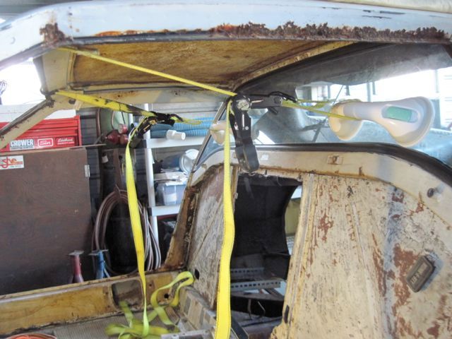
Finally, use some cargo straps to apply even pull force:


At the end, this is a two person job. Remember to wear gloves and eye protection in case something goes wrong.
Last edited by ufo-low

Add Reply

Post
×
×
×
×
Link copied to your clipboard.
×