
I have enjoyed and learned so much from this forum, it's time I contributed my share. Hopefully other owners or prospective owners may benefit from my efforts - and avoid some of my mistakes. I'll start with a few pre-restoration photos:


What I have here is a text book 30 foot car. My goals are modest; to have a clean, straight driver of a car, yet I have no illusion that it will be easy to achieve. I know I have rust and accident damage, and I'm sure I will find more problems as I go on.
Last edited {1}
Original Post

Replies sorted oldest to newest

Now let's take a closer look -


Look closely between the lens and bumper


Not Good


I think there is some bondo here. Actually, the paint just recently came off; it did not look nearly this bad till now.


Not Good


Bad


Really Bad


Ugh


More Ugh


Seriously Bad


The other side is almost as bad


I had to show this one; this is the only dent I have made since I bought the car in '96. Backed into a fire plug hidden in weeds.
Last edited by ufo-low
David, Rob and I have already been in touch. All was set until MY daughter uncovered the plot, and the gig was up. I did buy a few pieces from him though.

Mikael, I am sure you know the warning - never buy a rusty Pantera. That is unless you can weld and have a lot of time - or money. I can weld.

Larry, yes, that's my shop and I built it with this project in mind. The chassis is on a rotisserie now, and all the parts are in boxes. Lots of boxes.
OK - I've been officially busted. Dang. I was going to post a flurry of activity here and have you all believe I'm some kind of restoration super guru. More like the Wizard of Oz. Oh well - the show must go on.

I started with the deck lid, as it seemed pretty straight. I had an annoying pimple dent to deal with.


Hard to see in a picture, but obvious in person.

I also want to square up the left rear corner:


Compare it to the right side:


Notice how the left side has kind of a wedge shaped gap. The infamous paint chipping problem is obvious, but a new latch striker and chassis stiffening should fix that.

As for the latch striker, the early cars had a really weak affair with no lateral support; I don't have a pic of it handy. Here is where it goes:


I also have one broken strut mount support:

Last edited by ufo-low
I'll start with the strut mount. The broken bracket puts all the load on to the bolt cantilevered, and I can see it is bent. To see how much, I put a long straight steel rod through the hinge pin holes to use as a reference. Laying a straight edge across them shows me how much.


Compared to the other side:


First to cut off the remains of the bracket:


And clean up the area:


Next I put an allen head cap screw in the mount nut, and found a jack handle that fit snugly over the head. Applying some O-A torch heat to a dull red, I carefully straightened the mount nut:


See - good as new:


Next I'll measure the strut eyelet, and set the position of the new bracket:


Now to make a paper template. The metal is curved, so I had to find a way to match it. A large plastic can lid did the trick:


Here I mark the size of the bracket and the location of the bolt hole:


Now the screw head is bigger than the hole I need for the shank, so I need to find the center:


Also I want the bracket just a bit bigger than the eyelet, so I mark the radius and finish the template:


Transferring the template to 16 gauge steel, drilling and reaming the hole for a nice snug fit, and finishing the bracket:


Finally, to weld the bracket in place, I used washers to space it out, and had to use a different screw because the allen head was in the way of my welder:


Same for the other side, and done.
Last edited by ufo-low
Next task - fit a new latch striker. The one that came with my car, not sure if it was a factory item, but it was useless. Next time I see it, I'll take a picture of it before I throw it in the garbage.

Here is the mounting area:


I bought a new one from Panteras East, but the later models mount differently. I had to adapt my deck lid to accept the later style striker. To do this, I reinstalled the deck lid and the latch mechanism. I set the striker in place, and marked the new bolt locations.


How did I get this photo? Remove the A/C condenser and grille, and there is enough room to look up inside.

I drilled the holes, and found these nifty "T - nuts" in 8 x 1.25 mm (IIRC):


Remember to grind off the plating from the area where you intend to weld, or it will not weld well at all. The original studs were buggered up, and no longer needed, so I cut them off.


Here is how it looks, awaiting only some primer and a bit of cosmetic touch up:

Last edited by ufo-low
Here are a few pics of squaring up the corner. I felt it was a bit too much to just slap some filler on. It would be too fragile, and might chip off if bumped later on. I decided to put some metal behind it.


A few tiny spot welds on the wire give it the strength and stability I need:


After grinding them smooth (no pic of that), I filled in with JB Weld.


After the JB weld set up, I sanded to the desired shape.
Last edited by ufo-low
Mikael - no tricks - I wear gloves. Cool
When my hands are really dirty, I try to keep them out of the picture. Also not good to handle a camera with greasy fingers.

Thanks for reminding me about those decklid securing tricks, I remember seeing them both.

These pics show how useless the original bumpers were:


Last edited by ufo-low
Finishing up the deck lid metal work:


Finally getting all the old paint off reveals a very clean original piece.


The "Power by Ford" emblem mount holes


And a couple more on the left rear upper surface


Funny, there were no similar holes on the right side; like someone started to mount a wing and gave up. Strange. All these I welded shut.

These recesses are a bear to get paint out of:


You can't sand blast in there - it just blasts right back out at you. Too small for a power tool. Just paint stripper and scraping by hand; sometimes using a mirror to see what I am doing. Lots more work that it's really worth.

Finally ready for the first coat of primer, and my first OOPS:


Do NOT mix epoxy paint in a plastic cup.

OOPS #2 - same day:


Do NOT drop the trouble light into freshly applied paint deep in one of the least accessible places on the car. (see above).
I reached in with a needle nose pliers to get the big pieces, and put double sided sticky tape on the end of a ruler to get smaller bits. After the paint was dry, I scraped out everything I could, and applied another coat of paint to cover anything I might have missed. UGH - several hours of extra work.

I brush painted in the really hard to reach areas, then sprayed the first over all coat:


My make - shift paint booth did not work very well. It came out OK, but was a pain to set up and tear down. The deck lid is the only piece I did this way. I came up with a much better method later.

This bad boy is heavy, here it goes back on for some test fitting:


I sanded off most of that first coat; you can see little patches of it in this photo:


Thought I had a pic of it all done - but maybe not. I'll take one next time I get it down.
Rodney
Last edited by ufo-low
On to the front trunk lid. First to survey the damage, find what needs fixing, decide how to repair it, and in what order. Working on anything you have bought used is a bit of a mystery. It takes some detective work, looking for clues, to uncover the hidden faults.

This piece is going to be harder, that is for sure. It seems to be sprung - bent - on the right side. It does not sit level with the fender. Only 1/4 inch, it does not show up in photos much, but easy to see in person.

Rust on the lip; more so on the right side:


Here is a clue that the problems are more serious than they first appear; first the left hinge:


and the right:


Bent.

After stripping the paint, more problems are seen:


Dents in the frame near the right hinge mount.


Rust pitting along the lip inside and out.

And the last clue - dent puller holes:


On the right front. Hmmmm - a pattern is emerging.
Last edited by ufo-low
First I want to try to straighten it out. I think if it is bent, the frame and skin were bent at the same time and by the same amount, and I should try to straighten them together.

To find the damage, I decided I should measure the trunk lid carefully.


Here I've put it up on my 4' x 4' table. The tape along each edge is marked every inch from the back to the front. It is just over 51 inches long. I put cabinet shims at the corners to get them an equal height up from the table surface.


Here I am measuring, at each inch mark, the height from the table to the surface of the metal. Each measurement, and the mark at which it was taken, is written down; over 100 data points in all. Now a table of numbers is not very easy to see the trends, so I put the data in a spread sheet, and printed a graph. Now it is obvious where the damage is:


The horizontal axis is inches, with 0 at the back (near the windshield), and 50 at the front of the car. The vertical axis is in 1/1,000 of an inch, so "500" means 0.500 inch, "1000" is 1.000 inch, and so on. Clearly the right is bent up almost 1/2 inch compared to the left.

Now, being an engineer, I wanted to use a precise method to straighten the trunk lid. So ... I got up on the table, put my foot on the high spot, and stood my weight on it until I felt it "give". I was really afraid that I had made matters worse, but I shimmed the corners and took the measurements again:


Wow. Got it perfect on the first try. I actually put the trunk lid back on the car just to prove I wasn't fooling myself. Fit great! Declare victory and move on!
Last edited by ufo-low
quote:
Originally posted by UFO-LOW:..I decided I should measure....Declare victory and move on!


I think you will appreciate my buisness motto signiture line as it is very appropeate for your work

“when you can measure what
you are speaking about, …
you know something about it;
but when you cannot measure it, …
your knowledge is of a meagre
and unsatisfactory kind…” Lord Kelvin 1883
You betcha - I was certainly aware that it was possible I could do some expensive damage. Like when I repaired the pimple dent on the deck lid, I put the O/A torch to it, and that deck lid skin bowed up about 2 inches; that got my attention. Thankfully, it returned to shape when it cooled.

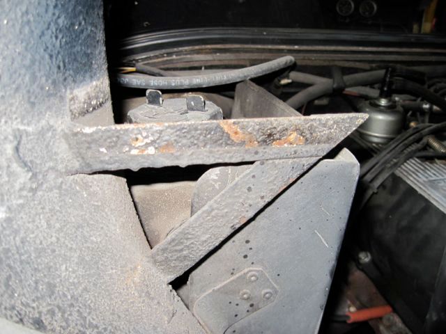
Anyway, on to the next task, fixing the rust and damage at the front. This required some more measuring; to calculate the radius of curve. I measured the piece before taking it apart so I could make the repair pieces to fit.

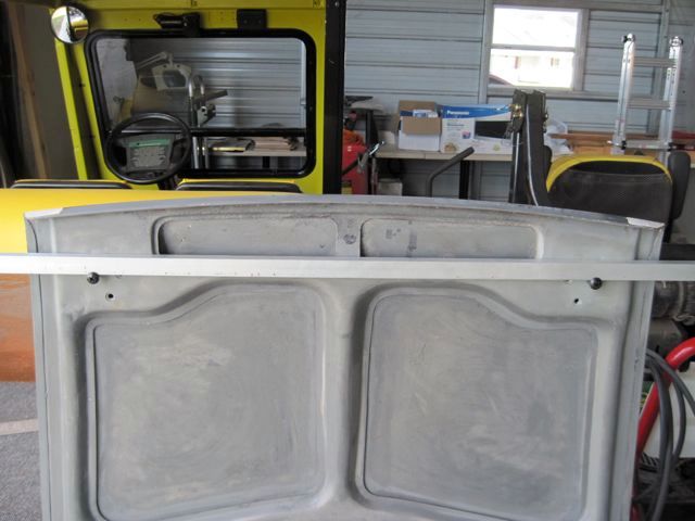
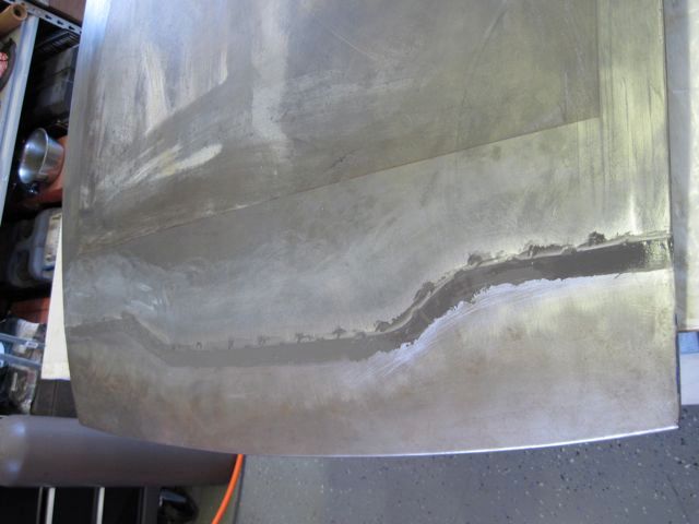
This is just a stiff, straight piece of aluminum channel, held with some screws in the outer most hinge bolt holes. The only purpose is for a reference to measure from:


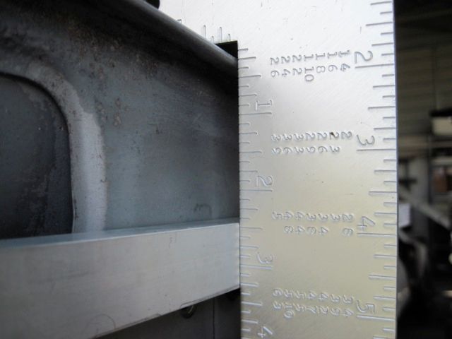
Now to take a measurement at the outer edge:


and one in the middle:


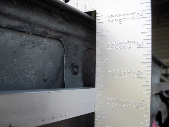
Now I won't bore you with the math, but if anyone is interested I can give you a link to find the formula on the 'net. Mine worked out to be 123.5 inches of radius (just over 10 feet).

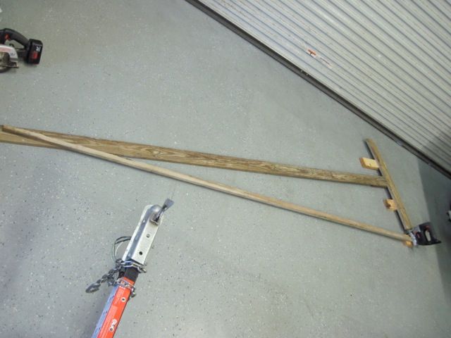
This is a pic of how I improvised cutting such a radius with my saber saw. I am cutting wood here, not metal. Two pieces were cut to use as a guide for cutting the metal, and as a buck for bending it.


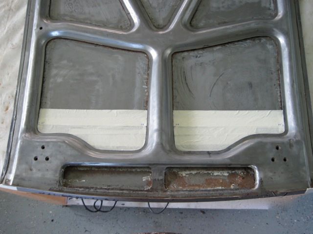
As I am looking at this, I see I can use the frame to hide the repair from the inside, so I don't have to do any cosmetic work there. Not having X-ray vision, however, I have to locate it on the outside. Here some masking tape is laid in and marked:


With help of the reference marks I made earlier, I marked the frame on the outside.


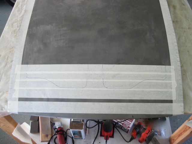
I moved the cut line about 1 1/2 inches forward of this, to be sure it would be hidden by the frame, and cut the metal with the die grinder:


Having never seen inside, I had no idea what was just behind the skin, so that is why I did not use the plasma cutter for this.

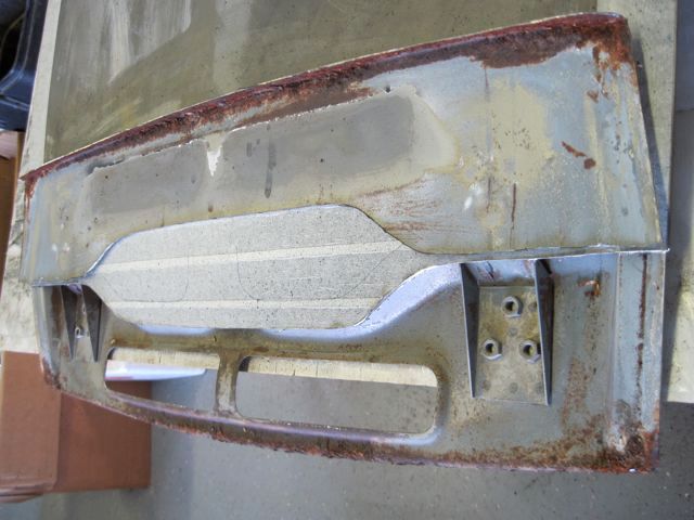
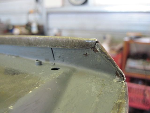
I can see now that the leading edge of the frame will need to be replaced too. This is a complex piece, more so than the outer skin. I did not think I could create the stamped contours, so I decided to leave as much of it as possible intact.

Here I've cut off the rusty lip, leaving about 2 inches at each end (just out of view in this pic):


The remaining metal is cleaned up and treated with ospho, but it is still rust pitted, so I do not think I can weld to it. I decide to put on the repair piece with panel bond epoxy and a few pop rivets.

Now to start on the repair pieces. I've learned to use a wood guide with the plasma cutter; it holds the tip just the right distance off the metal, and gives a smooth fast cut.


Here is the soot from annealing the metal before shaping it:


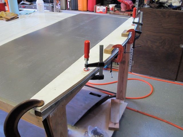
Clamping the new metal between the wooden bucks I made earlier, I bend the lip on the frame repair piece:


One more pass with the plasma cutter, and I have the frame lip repair piece in rough form:


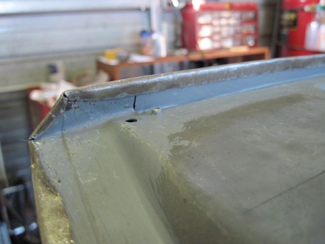
I have to shorten it, and use the shrinker to form the compound curve to match the remaining frame material. Here it is being bonded in place:


I also added some pop rivets, and hammered the leading edge lip over some more, as it has more than a 90 degree bend, but I could not have got it into the shrinker jaws had I done that first; so I had to do it after installation.

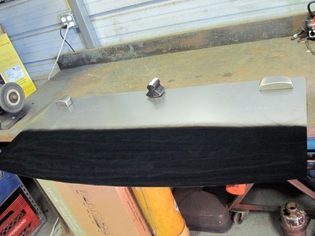
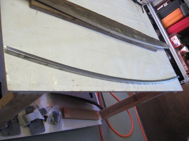
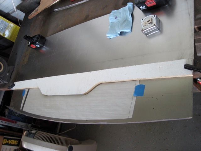
Here I use the same wooden bucks to bend the lip of the skin repair piece:


Notice I left more material, as this has to crimp over the lip of the frame I just installed. Also notice how the metal buckles some when bent over. No problem; the shrinker will fix this when I put the proper crown on the piece.

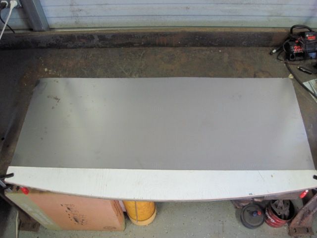
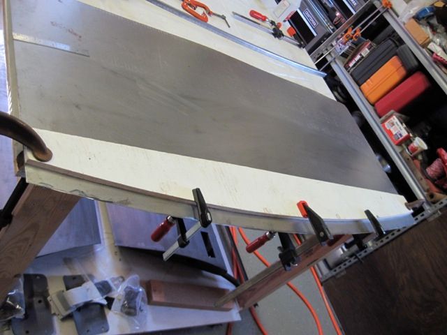
I made a wooden fence to match the cut on the skin, and used it to guide the plasma cutter:


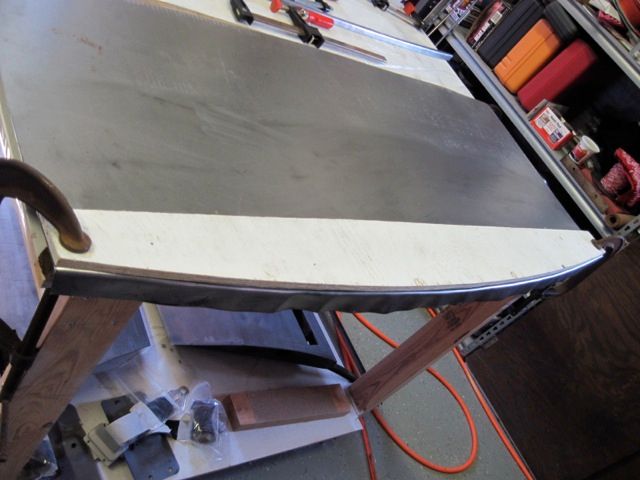
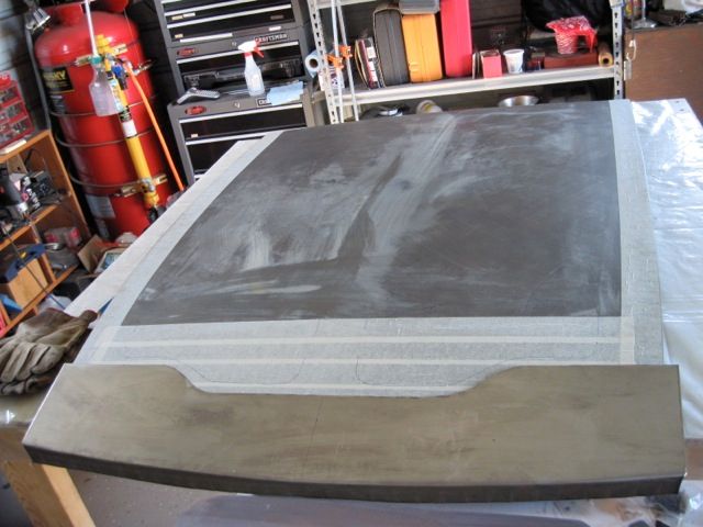
I cut off some of the excess width, and shrank the lip to put in the necessary crown curve. Now it is starting to take shape:


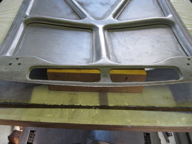
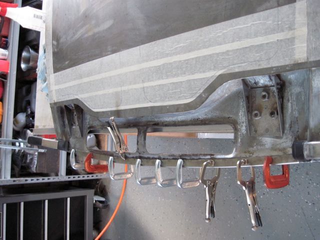
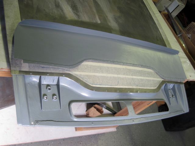
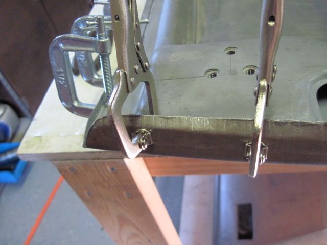
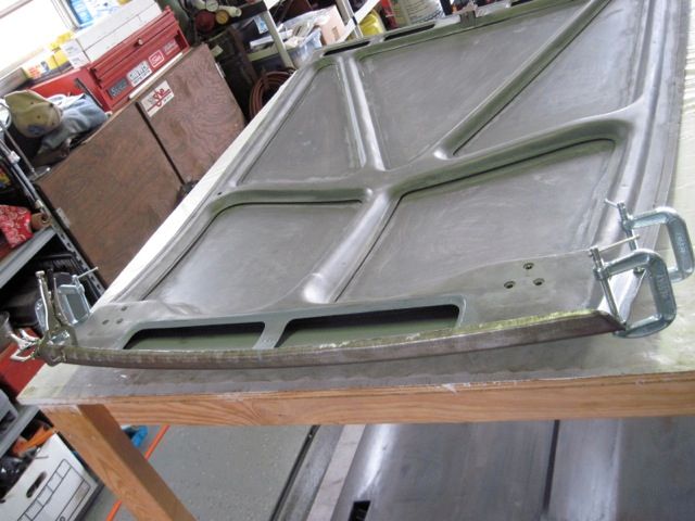
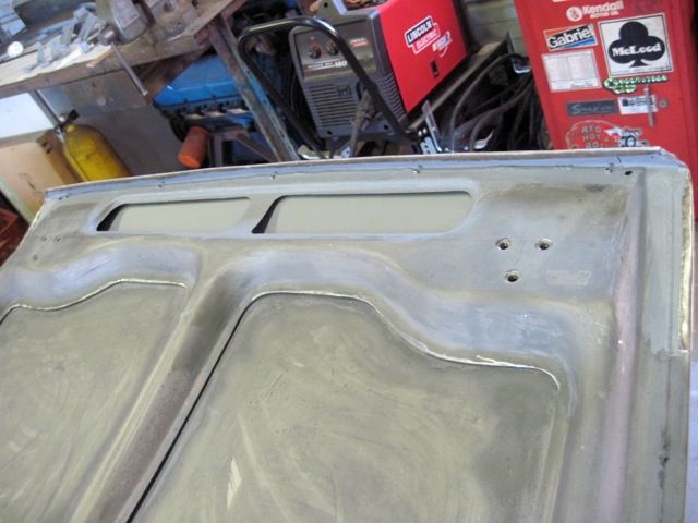
Here I'm just about ready to put the patch on. You can see how the frame repair came out, and I put in a couple of small drain holes. It is all cleaned up and epoxy primed on the inside. The overlap is flanged and drilled for sheet metal screws that will hold it together for welding:


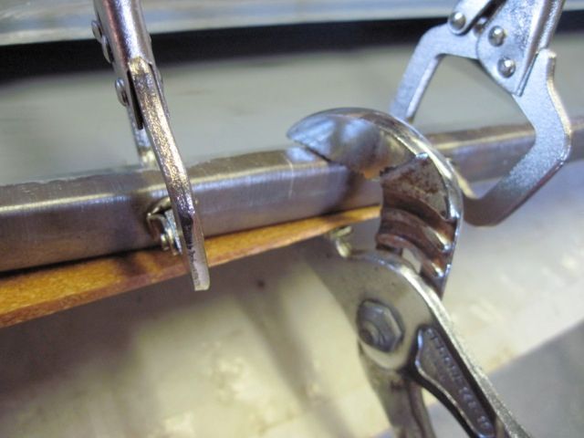
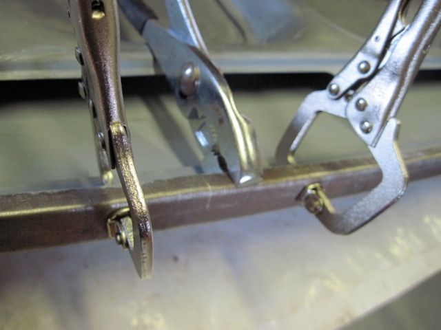
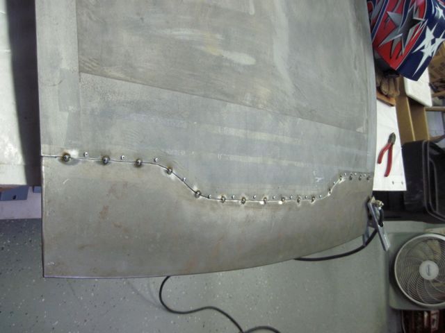
Here it is screwed in place, and I am starting to bend the edge flanges over:


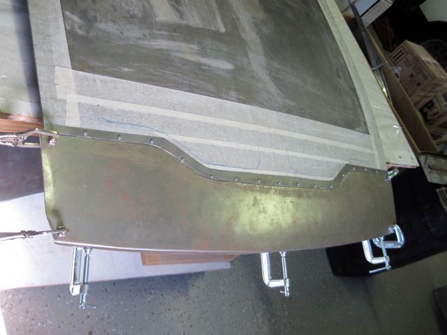
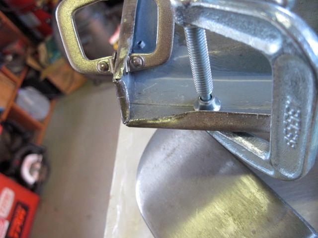
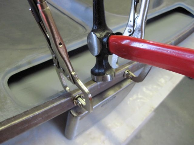
Here is a series of details of bending and crimping the edge flanges:


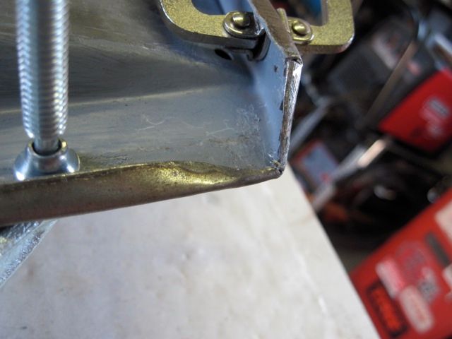
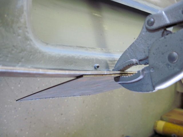
After finishing the edges, I spot welded along the joining line, removed the screws, and welded the holes shut:


The depth of the flange crimp my tool makes is not exactly the same as the metal thickness, so there is a very small step. I filled this and some of the weld divots with epoxy:


WHEW!
Last edited by ufo-low
Yes, JFB has it.

Can be reduced to

r = (c squared / 8m) + (m / 2)

Anders, I think from over head view, the radius of the front cross member should be the same as the front of the lid, or it would not look correct. From front view, I think it is flat.
I will take some measurements and pictures tomorrow for you. Rodney
Here is an example of one of those dinky little jobs that turns into a real time eater. I wanted a new stainless steel latch pin for the trunk lid.

The original was worn and rust pitted;


I did not take a picture until I had already started to remove the old one. Now if you give a quick look, the pin is welded to a sub-bracket, which is welded to the trunk lid frame. It appears that the pin is spot welded to the sub-bracket at the ends, which it is, and grinding those welds off will free the pin. No, it won't. The pin is welded to the sub-bracket on the inside too. I had to slice through the sub-bracket along the length of the pin to remove it;


Next I tacked in a strip of metal to fill the piece I had to cut out;


This left the ends pretty butchered up;


Two small stainless flat washers were fitted to the ends and welded in place;


A few more spot welds to strengthen the whole affair, and the new pin can be welded in place;


After primer, it looks OK, not great;


It may have occurred to you, as it surely has to me, it might have been easier to cut the old sub-bracket off, pin and all, and make a whole new one. Had I known that the pin was welded on the inside, I probably would have done that.
Last edited by ufo-low
quote:
Now, being an engineer, I wanted to use a precise method to straighten the trunk lid. So ... I got up on the table, put my foot on the high spot, and stood my weight on it until I felt it "give". I was really afraid that I had made matters worse, but I shimmed the corners and took the measurements again

Brilliant! Love it!
Alright - back to work. To finish (for now) the trunk lid with primer and base body work.

Here is the piece just after the first coat of primer:


Next a thin all-over layer of body filler:


The first sand off reveals the low areas. Marker shows me where to go easier on the sanding to achieve a little build up:


More filler in the serious spots, and some glaze putty for minor smoothing:


The next round of sanding gets it closer. Funny how you can clearly see where the frame is, even though it does not touch the skin in most places.


Here I found a "nick" in the edge. Too late to be welding on it, and too big for just filler. I put a dab of JB Weld in it, and put a piece of tape around it to hold it while it set up:


Remove the tape:


and sand smooth:


Here is my new painting solution. I've set up a temporary support frame on my trailer. I hang the piece with wires, and roll the trailer outside. Then I can spray all around the piece without moving or touching it. When finished, I clean up the spray gear, and push the trailer back inside out of the weather.


Before:


and after:

Last edited by ufo-low
Here is a tip I think others may find useful. I've heard it said that the pantera's glass is easy to remove, yet I've also heard many reports of breaking glass while removing it. The issue I found was the gaskets, having not moved for 44 years, are quite stiff.

I used some 1/4 inch plastic poly water line, and tucked it under the lip of the gasket on the inside of the glass. Here I'm doing a rear quarter window:


Tuck the plastic line in all around the window, except the corners. This flexes the gasket out a bit, and gives it a ramp like surface to slide on. Spray WD40 or similar in there too:


Then pry the glass, trim, and gasket out all together. Use as wide a tool as you can, and get under the gasket. Do not pry on the trim, it will bend easily.


Do NOT try to remove the trim alone. You will see why when you get it apart. The trim has a retention flange on the back, which fits into a groove in the gasket. The gasket traps the flange when installed in the car.

Last edited by ufo-low
Here is the same method on the cockpit back glass, with a new trick.

Pry up the lip of the gasket and tuck the plastic tube under. Spray lube in here also:


These handles with suction cups are meant for use in the shower, to avoid slip and fall accidents. They work good on glass, and cost less than the pro auto body tool:


Apply inside the cockpit:


View from the engine bay:


Finally, use some cargo straps to apply even pull force:


At the end, this is a two person job. Remember to wear gloves and eye protection in case something goes wrong.
Last edited by ufo-low
I prefer to call it the inspiration of desperation. Improvise, use the tools and materials on hand, don't be afraid to goof up sometimes, and refuse to give up.

Next I'll get on with cleaning up the engine bay. The gas tank has to come out. Mine was easy, as it was not being held in (!!!!):


There has been an odd creaking noise coming from behind me, ever since I've had the car. Whenever going over sharp bumps such as a railroad track. Now I think I see why:


I'm not going to be a real stickler for originality, so I want the clean bay look. I used an air chisel to remove the metal straps for the A/C lines and electrical bundle. This proved to not be so wise. It tore away the base metal, and left me with holes to fix:


Here the hole has been rounded and I am preparing to weld in a small plug. Using magnets to hold it in place. Magnets really mess with the welder's arc, so use another method if possible. That super sticky aluminum tape used on A/C ducts works pretty well.


I've used an air powered scraper tool, and in some places ordinary paint scrapers, to get most of the "tar" off. Heating it helps to soften it, using a heat gun or propane torch. Use care; the stuff will burn if you get it hot enough.


Following that with rags or paper towels soaked with mineral spirits yields a clean (?) metal surface.


If you have high humidity like I do, wipe the bare metal down with ospho (a phosphoric acid solution) to slow down surface rust.

Here I am going to remove this grounding stud, which I don't use. Shortly after I bought the car, I moved the battery to just in front of the right rear tire, and ground directly to the engine block. Of course, if you are staying all original, you would not do this.


This tear is on the left side, at the emergency brake cable opening. Possibly damage from a stub axle failure, as the axle opening was a little beat up too. Pics that follow show the repair process, which was pretty easy in this case:


Here is a little tip I learned; if you can reach both sides of a repair, and one is more visible than the other, weld on the less visible side. It will save you time on post weld grinding and finishing.

OK, another departure from originality. I have stabbed myself for the last &%^*$*! time on these things:


I actually cut off a couple of chunks of rubber hose and shoved them on to these brackets to keep from really hurting myself. If you intend to keep them, I suggest you do the same while you work in the engine bay.

Going for the clean bay look, I decided to make new brackets not only for my safety, but because they were ugly. The factory welder had blown a hole through the sheet metal at one of the welds; never fixed it. Been there 44 years as far as I can tell.


Here is my design for the new bracket, with the cardboard template I used to shape it:


Removing the original brackets left patches of rusty metal and some holes, which had to be fixed:


Before removing the old brackets, I measured their positions, and made a simple wood brace to reach from left to right. Here I am using it to hold the new brackets in place with clamps. This way, the new brackets support the engine cover panels in the same positions as before.


A test fit of the covers:


Next I'll scuff up the metal, and grind off any burrs and other obvious defects.


Give it a good cleaning, and apply the first coat of epoxy primer with a brush. It doesn't look so great, but most of it gets sanded off anyway.


Here was a factory boo - boo. The inner and outer panels did not completely overlay, and there was a funny looking gap here. Cosmetic mostly, but easy to fix with a small piece of metal welded in:


Finally about to wrap this part up. The inside of the engine bay is really wavy; it will take a lot of work to smooth it out. Right now I am just going to address the gross issues. This is not the end of my work here, just reached a point where I can leave it and move on.


This coat was sprayed:


Last edited by ufo-low
quote:
OK, another departure from originality. I have stabbed myself for the last &%^*$*! time on these things:

Oh man! I feel you bro! Can't tell you how many times I stabbed myself or nearly lost an eye on those damn things while refinishing my engine compartment. I came really close to cutting/grinding off the point, but ended up zip tying a bundle of rags on each one.
UFO, with some 95 changes from stock in our Pantera, I never criticize anothers' work, but I do sometimes suggest more.... like cutting the under-engine crossmember & e-brake bellcrank support loose and making them removable. The first time you need to pull the oil pan and run into that welded-in-place crossmember, you'll wonder why Ford never did this. DeTomaso did make those parts removable, once he regained control of his project. Each car has slightly different dimensions between the rails, so either a custom piece or shim to size. I made my bolt-in crossmember from a 2-1/2" OD thickwall aluminum pipe. Others have modded the stock part or made a billet aluminum structure.
Next I’ll show the repairs needed around the windshield. This is all rust repair, and it involves pieces of several panels. Here is what I found after taking the windshield out:


This brazing and lead work appears to be original, where the very tops of the A pillars meet the roof; I’ll leave it alone if I can:


These rust holes are along the roof line, and I have put marker dots on each spot weld I have to drill out:


Now I have cut the welds and cut out the rusty strip of metal. About 2/3 of this upper channel at the roof line needs to be replaced. It is easier to smooth a weld at a sharp bend, so I cut right along the front most edge:


It is good to see the rust had formed from the outside in. Once I scuffed off the surface rust on the inside, the remaining metal is in pretty good shape.


There were a few places where the rust had pitted the roof panel badly enough I did not think I should leave it. Here I’ve cut out a segment, and am preparing to weld in a patch.


Here is something I learned about welding in small pieces. The small patch piece will heat up a lot faster than the big panel being repaired, and it is very easy to blow holes in it. So leave extra metal on the patch, and cut it off after the welding is done. Some times, it is not possible to do this, but it helps when you have room to do it.

Here I am fitting the repair piece in the windshield channel up by the roof:


Here is another rust pitted area over on the driver’s side. I’ll weld in a strip of new metal:


After repairing the edge of the roof panel, I’ll fit in the repair piece of the windshield channel, and tack weld it in place.


Now normally I would plug weld in a repair piece like this, but in the windshield channel, I decided to tack weld the edge of the repair to the inner frame. I did it this way to not have a bunch of plug welds in the windshield channel, which I would have to finish smooth and flush. I want a smooth surface for the windshield gasket to seal against.

Where the repair meets the roof panel, I stitch weld them together so there are no pin holes to leak. Here I had a bit of trouble, and had to cut out a small section and do it over:


Now to work on the lower part of the windshield channel. This is formed by the rear most edge of the front fender panels, and by the vent cowl. I suppose I could do this repair all in one piece, but that would be cheating. Seriously, if anyone needs to work in this area in the future, it would be a pain to have this all in one piece. I’ll make the repairs to match the factory panels, and leave a small gap in the channel for water to drain away.


Much like along the roof, the rust has damaged the channel and the edge of the panel. Here the channel and fender are cut apart:


The spot welds are located and cut out:


Here the damaged edge of the fender panel is cut away:


I have adhesive tapes of various widths, they help guide me to make a uniform cut. It is much easier to make repair pieces of uniform size.


A small segment of the cowl is rust pitted, and needs to be replaced:


After welding and smoothing, I have solid metal to work with:


Next I’ll weld in the repair piece on the fender:


Ok, almost done with this area. Notice how the repairs of the fender and cowl sections are separate, as original. If this area ever needs work again, it will be much easier to do. I will leave the small gap as a water drain.


Only the very bottom of the A pillar part of the windshield channel was rusty. Thanks for small favors. This patch segment was welded in here:


The repairs on the right (passenger) side will have to wait. My right front has both rust and accident damage. It will be one of the last areas I repair, and I will complete the windshield channel on that side as part of the over all work on that area.
Last edited by ufo-low
The right front fender is the only panel that has to come completely off. There are plenty of clues that this car has been hit here at least once:


I can see there is a LOT of bondo here. Normally one would sand or grind through it, but I chose not to do that. I figured that would take a lot of work, time, and create huge amounts of dust. Also, I could have just cut off the whole panel bondo and all, but I could see that major portions of the panel could possibly be saved. I wanted to get most of the bondo off so I could see where the serious damage was.

It is fortunate that I can get to both sides of the panel in most areas. I used a propane torch to heat the inside of the panel. This causes the bondo to soften and release it’s bond to the metal. Of course, I can’t heat the whole thing up at once, so I used cabinet shims to wedge the bondo off a little bit at a time.


Maybe there should be a prize for the biggest slab of bondo ever removed from a deTomaso:


This is what was underneath:


Be careful when using a torch to heat things; some will burn:


This filler panel between the A pillar and the fender panel I call a contour filler. I can see this was damaged and brazed back on in the past, but I have to be cautious here. The fit of the fender with the door was reasonably good, so I can say that this past repair, although ugly, was fairly well done. I may end up leaving it if I do not find any structural damage.


Next I’ll remove the rest of the bondo and see if the fender can be saved:


This part, I don’t think I can save:


This clue makes me believe this car has been hit at least twice here. Not only is the replaced fender damaged, but the original metal that it is brazed to is badly damaged also:


Here I am separating the fender from the contour filler:


I tried to melt off the brazing that holds the fender on (this is not original, of course). You can see I got it very hot in front of the head light opening, and near the hinge, but I was not successful. I decided to cut the panel off. I used a plasma cutter to cut in the bottom of the drain channel between the fender and the front hood seal flange. That way, I can hide the repair when (if) I put this panel back on.


If I have to use a new panel after all, I will have to cut away the remaining material also.

Here I cut off the area near the windshield channel and cowl:


And finish separating at the contour filler:


After cutting the panel away from the obvious areas of previous repairs (no pics), the panel finally comes off:


More damage is uncovered:


This piece near the windshield channel and cowl must come off:


This reveals even more work that awaits me:


This is going to be fun …. not.
Last edited by ufo-low
Holy cow UFO... you're rockin!! Very commendable... !! And...yes...I do believe you get the award for the biggest slab of bondo. You can call it your "lightening" project, as you likely will take 30lbs out of the car by the time you are done... Big Grin

Great work man...! Keep it going. Now I have to get out in the shop and try and be as productive..
Think though Boss - the more people pulling mass bondo / bog out of these cars like this only makes the marque better in the long run again...

I'm seriously contemplating doing some courses to learn how to work panels so I can do this sort of work myself on cars. My biggest source of frustration with my project so far because its my first ever car project is just not knowing stuff...
Next I’ll show some of the work needed on the floor pans and under chassis stiffeners. This was damage from rust and some improper jacking. I also repaired holes left by the installation of some non-stock seats.

Here is inside left floor, after removal of carpet and pad (well, what was left of them; what a nasty job that was):


Outside, same area:


Most of the rust through was in these two areas:


Fortunately, most of the damage was out in the open, areas where there is only the one layer of metal. Not here, however. This rusty patch extended across one of the stiffeners, so I had to locate the spot welds and cut them out:


Here you can see the one area repair tacked in, and the other yet to do. Also see the jacking damage to the outer stiffener:


The right side does not look quite so bad from outside, but it has a lot of pin holes.


Here is a series of pics of the jacking damage on the chassis stiffeners, and the work needed to repair them:


I used the plasma cutter for most of the work removing the rusted patches and the bent stiffeners. Since I wanted to reuse the stiffener pieces after straightening them, I had to find a way to cut the damaged bits out more or less cleanly. Here is how I guided the cutter along the corners and bends. A small piece of wood, a hole drilled through for the cutter tip, and a groove ground along lengthwise guides the cutter tip. Obviously they don’t last very long, but so easy to make, just throw away the burnt up one and make another. Works surprisingly well:


Here is a little patch to cover some holes from a prior seat installation:


I could have fixed this on the inside of course, since it will be covered with pad and carpet no one would see it. Just decided to do it here while I had access.

Here is more of the stiffeners repairs in process:


I’ve cut out the rusty patches on the right side; funny how the rust damage is almost a mirror image of the left side. Must be low areas where water collects:


Some of the smaller patches I made, and welding them in:


A few more pieces to go:


Looks like Dr. Frankenstein has been here:


But hey, my quality control inspector approves:


My spider died and my toad moved out. Tough to find good help these days.
Rodney
Last edited by ufo-low
While you are doing this kind of work, there is one mod I really like. Look toward the bottom of the page where I mounted large eyelets through the frame:

http://www.rc-tech.net/pantera1/valance/valance.htm

I have already had a chance to use them easing the car off the trailer at the interior shop. The ramps were not that great and this was a great point to attach the cables to. BTW the airbags were very helpfull for ramp clearance:


On to the door frame surround on the left. Bad rust under the trim:


Just a little note about the weld in that last pic, between the rusty patch and the rivet hole. It looks like a butt weld, but it is not; it's a lap weld. More on this in a bit.

The rust on the edge where spot welds are is so bad, I can't see where the welds are. So, I went to the inside and scuffed the paint off so I could see them:


I still cut them on the outside however. Here I cut a small part out to see how the inside structure was made. The inner sill is kind of folded back around and spot welded to the inside of this rusty piece, but up closer to the roof panel. If you look closely, you can see the spot weld divots. If I cut any closer to the roof panel here, I will be cutting into it. This gives me an idea; I can use that inner panel as a guide for my panel nibbler's jaws. It will guide me to cut away just the right amount of this rusty metal:


Here you can see this worked pretty well:


I had to finish up at the fore and aft ends with a dremel. Finally the rusty strip comes off:


Again I am fortunate that the rust formed from the outside in. The inner structure is solid:


Pay attention when you make the repair pieces; this is 16 gauge steel:


Now to fix this bit. Cutting in tight corners can be difficult. I actually save my cutting discs when I have worn them down to 1 or 2 cm. in diameter. I use them in tight spots like this. I only get a few seconds of use before they're gone, but they do the trick.


See what I mean about this being a lap weld. Again, I’m lucky that the rust has only affected the outside; the inside is solid. I can clean this up and weld in a small patch:


Making the patch and test fitting:


Finally the pieces are clamped in place, tacked, welded, and smoothed:


Needless to say, I will NOT be using pop rivets to hold the trim on. I’ll use low profile stainless button head screws.
Last edited by ufo-low
Here is something I did not expect: the smallest pieces are the hardest to make. Without the special tooling the factory had, it is really difficult to copy some of the complex shapes, bends, curves, and folds of the factory pieces.

Here is one of the most complex areas of the whole car; what I call the upper B pillar junction. This is where the heavy structure of the lower B pillar ends, but a smaller section extends up to the roof line. It forms the frame of the cockpit back glass, the rear quarter window glass, and the upper back part of the door frame. The top fore-most part of the rear quarter panel, the top of the cosmetic door striker panel, the inner panel facing the engine bay (the one just above the gas tank), the rear wheel house longitudinal stringer, and the firewall cross member (with the upper seat belt fasteners), ALL come together in this area. It is very prone to rust. I have over 100 pictures of the work on just this area.

First to get the lead off:


Starting to see the metal, and rust, under the lead:


Now to cut out the rusty parts, bit by bit:


About 3 inches of this inner panel, below the quarter window, has to come out too.


I try to cut panels between spot welds, it is easier to put them back together that way:


I have to cut through these panels in my way, to fix the structure underneath. I spend quite a lot of time looking at this, to minimize collateral damage. If possible, I want to put these cosmetic pieces back on.


This corner where the cockpit back glass fits is trashed too:


Finalizing the cuts:


And it is off:


This piece I will clean up and reuse:


Next episode; cutting out the rusted structural parts. Stay tuned!
Last edited by ufo-low
If you have never had to repair this part, these pics should give you an idea of what you are in for. It will give you one of those “what were they thinking!?” moments. Here are four strips of light metal, two of which extend down to the top of the B pillar. Open to the rear where the tire can throw rain water, salt, and road trash at them. Just behind is a stamped in welding access hole that looks like it was designed to catch said trash, and trap it inside the structure where it can do maximum damage. Ye Gads!

Here I have already scuffed off the worst of the rust, and I have to ink mark the spot welds just to see them:


Now I have that junk out of the way, I can start cleaning up this area:


And get an idea of what this weldment looked like originally:


See where I have started to cut these pieces out:


Once you get the rusty junk out of there, and clean up the rest, it starts to look more manageable.


Here is a cross section cut of the vertical B pillar extension:


Another tip; keep all pieces of the damaged parts you cut out, no matter how bad, until the repair is completely done. They give valuable clues to guide you in reconstructing the parts. Even if you do not copy them exactly, in many cases I haven’t, they show the intent of the designer. Some times you can simplify, or even correct a weakness in the design, and keep a problem from occurring again.

Next episode: making the repair pieces and welding them in. Stay tuned!
Rod.
Last edited by ufo-low
Now for the fun part - putting it back together again. As I mentioned, there are 4 pieces to this weldment. I cut them off at different lengths, partly because that was where the damage was, and partly because it makes for easier repair. I labeled them and used a piece of tape to copy them. The tape is cut at the edge of each piece, and marked with a sharpie pen at the major bend(s):


Here are the repair pieces in rough form. Yes, it took a few tries to get them right. Notice on #4 for example, I left extra width so I could get a grip on it with my stretcher jaws. Cut the extra material off after I got the bend right:


This piece I will be saving, but I have to cut off this bit of rusty flange so I can make a new one:


The first piece to repair is the top of the cockpit cross member. I decided to do away with the pinch weld flange, as it really does nothing useful. The back glass gasket has plenty of flange to hold on to, and in this tight corner the flange kind of does more harm than good. If I find later that I need it, I can easily weld on a piece to replicate it:


Next to make a new piece for the inside of this flange; at the bottom of the rear quarter window opening:


While I’m in here, I am going to make a shield for this big hole. I brushed and vacuumed out the crud, and thankfully found no serious rust inside. I trimmed a bit off the flange, then fitted a simple metal shield:


I just want it to keep most of the crud out, but allow air in for evaporation. It is held with a single self tapping metal screw from below. I’ll spray some undercoating in the area later.

Here I have trimmed this inner panel flange piece and adjusting the fit:


This area is not easily seen, so I do not worry too much about making it pretty:


Now to weld it in:


Next to start repairs on this weldment. Starting with piece #2, it is the first one to attach back on to the upper B pillar. That little hole is original, from one the rivets that holds the trim piece on. It is a pain in the butt; I either have to leave it or recreate it. I chose to leave it, and I have to be careful about welding near it.


Here I pause to test fit the quarter panel piece I cut out of the way earlier. It hits the edge of piece #2 just a bit, so I’ll trim #2 off a tad.


Back to welding:


I had to use a small screw to align the rivet hole in this new piece with the original. There was so little room that a nut would have been in my way, so I used a split pin instead. The screw and pin were removed after the welding was done; they were only there for alignment:


Finally I have enough of the welding and smoothing done so I can spray some zinc primer in there:


Now to prepare the quarter panel piece to go back on. I welded some backer strips on it:


After some smoothing, it looks much better. There were also some dent puller holes just below this area which I welded up also:


Finally I have to weld in a strip of metal where the striker’s cosmetic panel meets the door frame; this was badly rusted out:


After touching up a few pin holes and smoothing, I pronounce this job done:


Time for a beer!
Last edited by ufo-low
Next I will detail my repairs to the A pillar area on the left (driver’s) side.

Here is kind of a “before” picture. To the right is the left (driver’s) door, which is toast. To the left and below are the front fender and outer rocker, respectively, which don’t seem too awful bad, right? Just a few rust bubbles, right?


Wrong! Here is what lurks underneath:


I’ve already started cutting out the rusty metal, see how bad it gets as I progress:


Here is one of those “what were they thinking?” bits.


These small assemblies I guess are meant to be splash shields, and I think there was some foam or rubber like material in the little groove. They may have done some good when new, but not long before the elements take their toll. Why not put it on the front of the A pillar where it would have done more good, and possibly have been serviceable? We’ll never know.

Next I have cut a piece out of the front fender; not only was it rusty, but the A pillar and contour panel behind it are rusty too.


With this out of the way, and the bottom of the A pillar cut off, even more damage is visible:


Notice the lap spot weld, where the mid-rocker joins the inner front wheel well surround. I had no idea the wheel well surround metal extended this far back; it is a good 3 inches rearward of the door opening.


This piece of the outer rocker / door sill has to come off because it is in the way; I will end up reusing this piece:


With that out of the way, I can cut out the rusty inner wheel well surround metal:


This pic shows the difficulty of repairing a damaged unibody. The floor pan metal above and below the stiffener is the same piece of metal!


The “floor pan” extends in one piece all the way out to join the mid and outer rockers at the flange weld. The stiffeners are spot welded to it, inside and out. If I needed to replace the floor pan, entirely, I would have to cut out all the spot welds to remove those stiffeners. I didn’t count them, but there must be hundreds. No thanks.

Back to cutting out rust and cleaning up the area:


Next episode; making and installing repair parts. Stay tuned!
Rodney.
Last edited by ufo-low
Here is my solution for the rusty floor pan between the stiffener and the flange weld. I’ve cut out the rusty piece, and made a replacement that will be welded to the stiffener. It will give me a new surface make a new flange weld on. I tried to make this in one piece, but could not get that curve at the front right, so I made it in two pieces.


This is test fitting and trimming:


Next to make repair pieces for the mid rocker and wheel well surround:


This is 16 gauge steel, so harder to work with. There are some tough compound curves here too:


This is the only easy piece:


Even a small portion of the inner rocker was rusted through, so I cut out a rectangular piece:


and made a small patch:


This access hole on the interior had an ugly rusty patch on the edge. This is only cosmetic, but I fixed it anyway:


I made the patch for the mid rocker overlap to the rear, just to add strength and be sure I had solid metal to weld to. I cut the rectangular piece out of the outer rocker because it was damaged, but it made a convenient access opening to weld through.


Next up; a slight departure from originality. Stay tuned!
Last edited by ufo-low
I have to side track my own thread a little. I had reached the point when I had to install my roll cage support stiffener, and this is not going to make sense unless I back up a bit to explain.
Some time ago, I decided I would put a roll cage in my car. Mostly for occupant safety, but also thinking about possible track day adventures. The SCCA rules describe the requirements, and I also looked at the work of other Pantera owners. (Thank you all for documenting your work; you know who you are).
I started by locating the end points of the main hoop and side hoops. You can see I’ve temporarily installed some of the interior trim. The green marker in these photos is a milk jug cap, which just happens to be 1.5 inches in diameter, the size of the cage tubing:


I did not have an idea how to make the tubing pieces fit, and I imagined that trial and error would take a lot of time and effort, along with a lot of mock up material. After giving it some thought, I decided to try a 3-D CAD model. Essentially, I would make a 3-D model of the car’s interior, and then draw a roll cage to fit within it.

These next pics show the set up of the X-Y-Z coordinate reference. Nothing more than some wooden yard sticks clamped in place inside the cockpit, and another yard stick with a level taped to it, free to move about and measure things.


Except for the mounting points, I did not measure where I wanted the roll cage to be; I measured the constraints. In other words, I measured the things the roll cage would have to clear. One point at a time, I filled in a table of X-Y-Z data points, with notes about what it was I had measured. I suppose this took a few days of shop time, a “shop day” being usually only a few hours a day. When I entered this data into my CAD program, the result was a crude, but accurate, model.

Once in the CAD program, I could model the roll cage, and try different designs. I let the computer figure out the lengths of the tubes and angles of the bends. I bought some 1.5 inch electrical conduit to use for a mock up. The bends kinked kind of bad in the mock up, so I’ll have to take care to avoid that in the real thing. The mock up verified for me that I had a good model, as these photos show:


While doing this I was thinking about the mounting points. Attaching a tubular structure to a unibody is not easy. Most designs use a steel plate contoured to fit on the inner rocker and held with multiple small bolts. I decided to use a different approach; a structural stiffener made of channel steel, inside the rocker. The roll cage will be welded to short segments of the same material, and these will bolt to the stiffener. The inner rocker metal will be sandwiched in between. These pics show it better than I can explain it.

The channel steel stiffener cross section:


The edge of the seat belt retractor opening is rolled in. I had to trim maybe 2 mm off the inside edge to allow the stiffener to sit flat on the underside of the inner rocker sill.


The mounts are two 3/8 - 16 grade 5 bolts at each mount, with nuts welded on the back side for more threads:


Here they are complete, one for each side, before and after painting:


Now, back to where was I? These stiffeners can only be installed with the front of the inner rocker channel open, as mine was thanks to all the rust repairs. Once it is installed, the opening is welded up, and it does not come out again.

Here is the inside view (this pic is the right side, while I’m working on the left; did not get a pic of it):


And finally the installation:


Standard disclaimer of liability: I can offer no assurance that this design offers any benefit or meets any specifications, or is suitable for any specific purpose, yada, yada, yada. If anyone chooses to copy it, you do so at your own risk. Nuff said.

Next episode; closing up the rocker and finishing the metal work.
Last edited by ufo-low
Thanks for the suggestion, JFB. Sometimes I over-think things.

Here is the constraints layer:


For perspective, imagine you are standing outside the car, off of the right (passenger) rear tire, looking toward the steering wheel.

The fire wall is obvious, the roughly rectangular pattern top center is the roof line from an interior point of view, the angled segments top and right are the A pillars along either side of the windshield, and the green balls are the left and right ends of the dash board where the cage has to clear them.

Next I've turned off the constraints and turned on the tubing layers:


Here the main hoop, the horizontal brace that goes across the cockpit at the shoulder belt attach line, and the side hoops that surround the door openings, are the only parts that have been mocked up so far. The rest only exist in the drawing, and are subject to change. I'm sure I will have to adjust the X brace at the fire wall to allow for access to the engine hatch. The struts back to the rear wheel house attach points are just a first guess also.
Last edited by ufo-low
With the stiffener installed, I can finish the mid-rocker and front wheel well surround repairs. The larger, trapezoid shaped piece was a bear; took a couple of tries to get it right.


I decided to put a drain / access hole here, so I can spray primer and rust proofing inside later:


Finishing up here:


Now I need to rebuild the bottom of the A pillar itself. I chose to use a simple wedge shaped structure. This will restore the original strength, but was also a minor goof up, as I’ll describe in a bit:


I find that the contour filler panel and fender are rust damaged up a little higher than I thought, so another 1/2 inch or so has to come off:


Here I test fit a piece of metal to repair the outer rocker; making sure it will mate up with the work I’ve done so far:


Now to weld in the A pillar repair:


Here is just a small leveling piece. At the factory they just pinched the rocker flange in here and spot welded the snot out of it. This area was very uneven, so it will help to have a clean flat piece to weld on:


Here is what I meant by a minor goof up. That steel rod you see at right center is laid in the door sill; it helps me line up things. In the previous pic, you can see that it misses the A pillar repair piece by a 1/4 inch or so. That part of the outer rocker that forms the door sill, continues forward to form the flange where the rocker and fender panel join. It should also be tack welded to the A pillar for support. Oops. Likewise, the bottom of the contour fill panel extends down to the same flange, and lays flat against the A pillar. Oops. I need to add a piece to bring the A pillar out further here. It is mostly cosmetic, so a light piece should do:


Next I’ll add a backer strip behind where the original metal and new metal join. This helps two ways. In many places, it is not necessary to weld a full bead along a junction like this; a good spot weld every 1/2 inch or so is enough. I also do not have to trim the edges so perfectly. When I’m done with the metal work, I’ll back fill this junction with epoxy, and she’ll be good as new.


Now I use the steel rod again to position the piece of the door sill I cut out earlier, and weld it back in:


Can you guess what this is going to be?


Now?


Now??


Here is where it goes:


Next to replace the bottom of the fender panel I had to cut off:


Fitting the new pieces along with the old:


Adding a backer strip:


More fitting


The repair of the fender ready to install:


When crimping an edge, I use the extra piece of metal as kind of a pad, so as not to leave jaw marks on the finished piece:


Finally ready to weld it up:


I added a backer strip to this original piece:


And welded it in:


From the back side:


I should have used backers on this piece too, but didn’t. No choice but to weld it all around. The welding is not that hard; the post weld grinding is time consuming:


Finally, inside and out:


Next up: splash shields. Stay tuned.
Last edited by ufo-low
There are several different gauges needed. Most all of the cosmetic panels are 22 gauge, so are the floor pans. The mid-rockers, front wheel well surrounds, and other structural bits are mostly 16 gauge. I've used some 18 gauge pieces also. I try to pay attention; been more than once I've made a piece of the wrong thickness and had to do it over. I can get small pieces of 22 and 16 locally, the others I have to order.
John, what are you working on now? Your gorgeous 5079 is all done, is it not? Rodney
As you might imagine, after having to repair so much rust damage, I have a keen interest in preventing it from happening again. While I had it torn apart, I spent some time looking at it to see why the rust formed where it did, and what I could do to prevent it. Any place within sight of a tire needs extra attention for rust prevention. The tires throw up sand, rocks, road debris, water, salt, tar, and all manner of trash. This junk hits anything nearby like a corrosive sandblaster. Any coating will eventually be eroded away, exposing the metal, which will also succumb.

Rust also forms anywhere debris and water are trapped. It’s impossible to prevent all water and debris from getting inside the unibody structure, so it is important to give it a way to get out.

My approach is to coat the underbody metal with epoxy primer. In areas exposed to the tire blast, undercoating will be used as well. Splash shields will protect the most vulnerable areas, and be removable for repair or replacement as needed. Some extra drain holes may also be added.

I started making the templates for these shields before I finished the A pillar work, because the area is easier to get to. Here is the cardboard and tape mock up:


The lower round hole is for the antenna wire, which I’ll not be using, so I will plug it. I’ll make a cover for the obround hole in the longeron, and cover the upper round hole along with the gap that is exposed into the ventilation cowl.

Here the area is cleaned up and the obround hole is covered:


The shields are held in with sheet metal screws:


These pieces are ready for their first coat of paint. The center and right ones are for the left front wheel well / A pillar. The left one in this pic is for behind the left B pillar. It would normally be hidden by the gas tank.


The more complex shields are made in pieces. It is easier to make them that way, and also to install and remove them.


Stay tuned for my next installment! Rodney
Last edited by ufo-low
Rodney, my current project is 7159. The car is remarkably rust free above the rocker panels. However both rockers and the front valence are compromised. I not sure how this happened. Perhaps a flood car? regardless, I purchased the car knowledgably and have finished rebuilding the valence area and support frame behind it. I am now rebuilding the passenger rocker area. As you know, the work is slow as fabricating parts and reassembling the structure is tedious. I'll post some pics later of the effort. Since I removed the entire outer rocker, there is a bit more to see. I purchased Wilkinsons, not the factory's, outer replacement rockers. They are side generic requiring you to trim of the extra to fit the side you desire. I also bought replacement middle rockers. However, the passenger side will not require replacement. My fingers are crossed that when I remove the driver's side, it is also repairable. It will be nice to get my money back on those inner rockers. Wishing that I had a 40" metal shear.
OK, now on to rust repairs to the bottom of the left B-pillar. First I strip away old paint, bondo, and some lead, so I can see the extent of the damage. At least that which can be seen from outside:


I’ll use some masking tape to section off the damaged parts, with attention to locate the spot welds and drains:


I may be able to save some of this outer rocker panel piece, but not what I find under it:


Now I have scuffed off the worst of the rust scale. I find what seems to be a good place to cut away the bottom of the B pillar:


This WAS 16 gauge steel:


So was this - the mid rocker:


Notice here the mid rocker is made in sections. I did not know this, and just happened to uncover a place where the lap weld is. Good to see the rust is only behind the B pillar.

This is the floor pan, just under and forward of where I am working. I spotted this damage earlier, and painted around it, knowing I would have to cut it out:


Cutting this away reveals the flange of the inner rocker rusted away too. I had to cut this out a little bit beyond what can be seen in this picture, to get back to solid metal.
I made a repair piece and welded it in, but did not get a picture of it.


Next to weld in a piece of 22 gauge to fill in the floor pan here.


Now I have all the rust cut out, and some of the pieces replaced. I mask the edges where I know I have more welding to do. Then I spray zinc primer inside, as I will not be able to it after this next patch:


This patch of 16 gauge steel was not too hard to make:


Next episode; I’ll make the B pillar structural repair, and start on some of the more cosmetic bits. Stay tuned.
Last edited by ufo-low
Pretty much expecting it by now Rocky. Some of the damage is obvious, and some leaves tell tale clues for me to find. What is cry - worthy is how much time it takes.
Jack, the patience I guess I was born with. The "talent" is just a matter of starting with the easier jobs and working up to the harder ones.
Oh, and lest I forget, a big part of "talent" is reading most everything that appears on this forum, and studying the work of Rob, Rick, Rocky, David, George, Comp2, Goran, Jack, JT, Johnny, Marlin, Larry; too many to name them all. A whole bunch of skill, talent, experience, and imagination is at your fingertips here.
On the structural parts that are not cosmetic (will not be seen when finished), I do not worry too much about making it look pretty or original. I have also learned that trying to make multiple bends in a repair piece is a good way to end up with scrap metal. Now I keep the pieces as simple as possible, and make more complex pieces by welding simple pieces together.

Here is a template for this repair using just masking tape:


Next I remove the template and use it to rough cut the repair pieces. Meanwhile, I mask off the welding zones, and spray in more primer:


This repair is done in 3 pieces; a flat panel with two wedge shaped bits on either side:


A little welding tip: that ugly bit of scrap metal clamped nearby is what I call my arc strike target. It serves two functions. The first arc strike or two with a MIG are usually not good. The wire is cold and the gas is not flowing. I use a scrap of the same gauge of metal I am about to weld. A few test strikes there gets the wire hot, the gas flowing, and makes sure my set up is right before I move on to the real work.

Again I mask and spray primer after the repair pieces are welded in place:


A few inches rearward, there were some rust through spots here, where the rear quarter meets the outer rocker. I cut out the rusty part, made a patch piece, drilled through a couple of new drain holes (not visible in this pic), and welded in the patch:


And after some clean up work:


This is a good example of how hard it is to get the contours and bends exactly right. Just off by a tiny bit, and it is plainly visible. Later, after the first coat of epoxy primer, I’ll smear a bead of epoxy (like JB Weld) into this crease, and after it sets up, I’ll burnish it smooth to match the original contours.

Tune in again for my next episode; I’ll wrap up the repairs to this area.
Last edited by ufo-low
This area was badly rusted out, and after taking it apart, it is easy to see why. I’ve cut away the top part of the outer rocker here (what was left of it). It used to extend all the way back to the B pillar, where just a notch was cut out of it, and it continued rearward. The door striker cosmetic panel was curved down and forward, lapped over, and welded to the rocker / door sill about where my cut line is in these photos. This formed a wedge shaped little cavity just perfect for trapping all sorts of dirt, trash and water in there.


The masking tape helps me rough out the shape of the patch needed:


Here is the rough cut:


After some trimming and contouring:


I decided to use backer strips on this one, so I do not have to get it so perfect:


Test fitting looks good so far:


Clamping it in place to be sure it fits up right:


Next I have to make up pieces to patch the quarter panel and the top flange of the outer rocker:


The bottom of the outer rocker piece had some rust through holes too, so I made a patch for it:


Here I am just test fitting the repaired piece:


And the other repair pieces are taking shape:


More test fitting:


I flanged the top of this piece:


This little piece is needed to fill in a gap:


One last test fit with all the pieces in place:


Now to start welding:


One of the challenging questions is which piece to do last. It is easy to paint yourself into a corner, so to speak:


I do not have a pic of the repair after clean up. I’ll try to remember to take one. It looks better than this.

Tune in again for my next episode; the infamous rear wheel house repairs!
Last edited by ufo-low
Yes, I will be doing that; thanks for posting your work on this. I remember reading it at the time.

I'm waiting on a new set of striker - receivers, so I will get back to this task when they arrive. I also had to buy new doors; mine were rusted beyond saving, so I will have quite a lot of "fitting" to do.

Question for you - did yours fit this badly? I remember this area was heavily leaded up when I took it apart.


Last edited by ufo-low
Funny you should ask, Steve. I bought the stretcher and shrinker tools from HFT. In the pic where I have the masking tape on the flat piece of metal, the outer flange has already been bent, so not easy to see in that pic. The inner flange is sketched on in marker. It is only 22 gauge, so it cuts and bends easily. I just bend the flanges to about 90* on the piece, then shrink the inside flange and stretch the outside one till the curve fits like I want it. Then trim off the excess if necessary.
This is pretty much a text book example of rear wheelhouse structural rust. I used a panel nibbler to cut upward just to find where the rust ends, and I have sketched some marks about where I think I need to go.


I used the plasma cutter here, since I could see this was trashed pretty much through and through. A little collateral damage is no big deal.


This is kind of strange, how this is put together. The light gauge inner panel must have been welded to the heavier outer stamping, then the subassembly welded to the frame rail. The outside panel of the frame rail is rusted and has to be replaced, but I have to cut away the inner panel just to get at the top welds. Not an issue in this case, since the inner panel is rusted also. If the inner panel were undamaged, I would still have to cut it away to fix this.

Before I start cutting this all apart, I made an “A” frame support to keep the rear end pieces in position. It connects the rear most suspension points to the bay brace, and to the fixed cross member just above the forward mounting points. I thought I had a better picture of it, and I’ll put one up later if I can find it.

Here you can see part of it, while I prepare to cut off the inner panel just below the obround hole:


With that out of the way, I can cut the spot welds and slice the outer frame rail panel to cut out the rusty section and the old welds all at once. I used a cutting wheel for this, since I don’t know for sure what is inside:


I also cut the wheelhouse again, up higher, because the rust damage went up farther than I thought. Using the cutting wheel gives me a clean straight edge to work with:


Finally it comes off:


Thankfully, clean and nearly rust free on the inside:


Here is the frame stiffener inside, next to the mount points. This is why I don’t use the plasma cutter when I don’t know what is in there; I could have destroyed this piece:


I decided to move my emergency brake assembly rearward, to make the cables shorter. This is where it ended up, and I’m welding some nuts on the inside to make for a stronger mount. If you stay with the stock arrangement, you do not have to do this:


With the area cleaned up, I spray in some zinc primer:


Next episode, I’ll dig into making the repair pieces.
Last edited by ufo-low
Here, I found the pics I was looking for.

First are a couple I took while taking the rear suspension off. The undercoating hides the extent of the rust damage:


That is not why I took the photos. See how little clearance there is for that bolt head? It cannot be put in the other way, because the motor mount structure is there. I must be sure to leave enough clearance to get this bolt in and out, when I rebuild this part.

Here is the brace I made to hold the rear end pieces in position while I do the repairs:

Last edited by ufo-low
This pic shows a technique I came up with to make models of complex pieces. On simple pieces, cardboard and / or tape works ok; I often use breakfast cereal boxes. On curved pieces it does not conform easily nor hold the shape. I tried aluminum foil, but it is too delicate. This is aluminum too, but heavier. I save “disposable” cooking pans from the kitchen, clean them out, and cut out the bottom of the pan. After smoothing and flattening the material, it works great for mocking up parts like this.


Earlier, JT asked me about the gauge of steel needed. This is one of the 18 gauge pieces I had to order. I could have used 16 I suppose, but it would have made for some uneven steps I had to weld across. Probably not too important, but thought you would like to know.


I had to cut away the inner wheelhouse panel here, which left me with a choice; do I reproduce the obround hole, or eliminate it. I decided to eliminate it. The rear most part of this panel is nearly flat, but the front part is concave, so I made it in two pieces:


Here I have cleaned up the weld zones, added a hole to allow rust proofing to be put in, and sprayed in some zinc primer:


On this frame rail repair piece, I decided to scallop the top to make places to weld. I just wanted less post weld clean up to do, since I have more pieces to weld in this same area:


Now tacked in place:


Here I am starting to weld in the inner panel repairs. This is 22 gauge, and I am welding it from the inside so it looks better on the visible side:


I had to weld from this side down where it joins the frame rail, but the upper seam came out quite nice:


Now to mask off the weld zones, and spray some primer in there:


I decided to make the structural repair in 3 pieces. With the simple workshop tools I have, it is just too hard to make all of these bends and get them just right. This is 16 gauge steel, and I have already tacked in the flat center piece:


This is my first try at this. Getting it round at the top and kind of rectangular at the bottom was a PAIN.


I decided to do away with the side flanges; I just could not get them right. I “T” welded the pieces instead. Here it is just about done with welding:


And after several coats of zinc primer, I’ll declare victory and move on:


Not sure what I will go after next; tune in again to find out!
Last edited by ufo-low
No, I had not seen Peter's work. He did a great job. Wish I had thought of that. I also have to fix the rear crossmember, bent from jacking.

Photos seem to be linking correctly now, but I still have hundreds of error messages from photo bucket; they look like sticky notes on the background of my browser display, making it hard to read anything other than the thread.

It's late and I have to get to bed, work tomorrow. Hope this will be cleared up by then.
It seems the photo bucket problem is resolved. That had me worried; no way I wanted to try to re-link all these photos with the text. I have learned a trick, though. To post this stuff up, I first choose the pics I want to use, then export them and upload to photo bucket. Then, I open a simple text file, write the copy I want with the pics, and put the links from photo bucket into my text file and save it on my machine. Then I just copy and paste the whole works at once into the forum entry window. That way, if it ever gets messed up, I can just pull up my text file, and I have all the information right there.

So on with the show. Here are just a few pics of the overall progress. Just to recap, I started with the deck lid and trunk lid. The metal work is done on them and they are in primer, wrapped in plastic and stored away. Then I cleaned up the engine bay and painted it. I removed the doors and dismantled all of the glass, trim and so on. The doors were so badly rusted I bought a set. Meanwhile, I pulled the fixed glass, and did the metal repairs around them as far as I could. The new doors arrived, and I stripped and repaired them as needed, painted, and test fitted all the mechanisms to make sure I had no surprises waiting there. They too are wrapped up and stored away. Next I repaired the floor pans, which had both rust and jacking damage. Then I worked my way down the driver’s side, front to back, repairing all of the rust damage. There is very little accident damage on this side of the car.

At this point, I cleaned up what I had done so far, and rolled it outside for primer, as you see here:


You can see I’ve already put some epoxy into the body seams where I need to contour them to make them uniform again. I won’t mess with it anymore until I am ready to do the second coat of primer over the whole thing. I have a few minor wrinkles to fix around the rear wheel arch, but for the most part, I’m about done with this side.

This side needs a bit of work yet:


When I work my way up this side, from rear to front this time, I’ll roll it outside and primer it again. Then I’ll take it off the rotisserie to do the front and rear repairs.

Stay tuned!
Last edited by ufo-low
The right side repairs are almost the same as the left, so much the same work needs to be done. Stripping off the undercoat reveals the rust damage:


The inside is always worse:


This side is not as bad as the left. I can see through the access hole that the damage on this side does not extend up so far:


This time I use the grinding disc to start, not the plasma cutter. Just to save myself from doing it twice, since I have a better idea about the extent of the damage that needs to be cut away:


Cutting the spot welds along the lower frame rail flange finally cuts this piece free:


Again, thankfully, very little rust on the inside:


Here I have trimmed away another 1/2 inch of the inner wheel house metal. Just to satisfy myself that there is only surface rust and scale between these pieces. Because of this, I do not have to cut the outer frame rail panel all the way to the top.


They are not welded together inside this structure, only on the engine bay side. This also gets the thin inner wheel house metal out of my way, so I can clean the frame rail pieces up for priming and welding:


Now, however, I have a hole on the right side, and not on the left. The simple answer is to weld a cover over this one:


Next, the frame rail repair piece is welded in:


Now to rebuild the outer structure:


Almost done:


Ready to do the last few welds:


Next episode; I’ll go back in time (a bit) to fill in some gaps.
Last edited by ufo-low
I got things a bit out of order. I actually did some of the right A pillar repairs along with the left. As they are more - or - less mirror images of each other, it seemed like a good idea to make some of the repair pieces at the same time.

Here is a look at the area before stripping it down:


It is amazing how much damage can be covered with bondo and paint. Scary:


No point in wasting time, taking the bondo off of a piece that obviously has to be thrown away and rebuilt from scratch:


I will toss it in the junk bucket and keep it till I’m done, however. Even a nasty scrap like this is helpful to recreate the contours in the replacement piece.

This is the lower front corner of the door frame, just below the hinge:


And here the inside view:


A shame the factory did not put a rock shield here. A simple piece of sheet metal would have made a big difference. You can be sure I’m going to put one in.

Starting to strip paint off the fender:


Cutting spot welds and sectioning the pieces to be cut apart:


The forward most piece of the outer rocker is cut free:


Revealing more nastyness:


Heating bondo and putty with a propane torch will soften it up, but be careful; it will burn if you get it hot enough:


There was a lot of bondo in here, covering up a slightly bent A pillar. I think this contour panel was replaced. I can’t see how you could bend the A pillar without destroying it. I’ll be looking closely at this area when I get to fitting the new doors:


Just like on the driver’s side, the bottom of this A pillar has to be cut off:


Rust never sleeps:


Starting to cut away the wheel well surround from the mid rocker and floor pan. Now having had the other side apart, I know where the lap seam is:


I had to cut another 1/2 inch off the bottom of the A pillar to get at the rusty metal under it. The tape is my guide for cutting away the damaged section:


And off it comes:


This car has rust in some bizarre places; this just below the fuse box mount:


Most of the de-construction is done here, so next time I’ll start to detail some of the re-construction. Stay tuned!
Last edited by ufo-low
I’ll start by sectioning out this rusty bit below the fuse box bracket:


Rough cut on the repair piece:


After some shaping:


Clamping in place to weld:


Raw welding work:


And after some smoothing:


View from the inside:


I decided to try a different approach to the floorpan corner where it curves in to meet the wheel well:


Here is the section that needs to come off; rusty and pretty beat up:


I will overlap the repair piece with the good metal that remains:


Test fitting:


A gap needs to be filled here:


Remember I said the little pieces can be the hardest to do. It took me 4 tries to get this little bugger right:


Next comes the bottom of the A pillar’s inner panel. I used a hole saw in this piece:


Then cut and flanged it to match the mating pieces:


This portion of the wheel well surround, where it joins the mid-rocker, is pretty straight forward. The screws are only there because I can’t get a clamp that far back to hold them together:


Now to start welding:


One more little patch, and a drain / access hole, while I can still get at this area:


Here I’m just checking all clear, before I put in my roll cage reinforcement:


Now to patch in this contoured piece of the wheel well surround:


These kind of pieces are a bear to get fitted just right:


Finally time to weld:


Not sure why I do not have any pics of finishing this area. I will take some if I need, to finish this part.
Last edited by ufo-low
quote:
Thanks Garth. Did you get your block fixed after it inhaled the air cleaner screw?

Nope! It's still with the machinist. They may have sleeved the #8 cylinder already, but informed me the piston was collapsed and needed to be replaced. Only problem, Probe no longer makes pistons! Since this is a stroker engine, I couldn't just purchase any other piston to replace the damaged one, so I started looking at the stroker piston offerings from other manufacturers - was getting crazy quotes of $1,000 and up for 383 stroker pistons, but only available .030 over, which means I would have to bore my block again to punch it out from .020 to .030. So I began searching the country for a set of .020 over Probe SRS forged stroker pistons for a 351C and found a set on the East Coast. Had to buy the whole set, but it was half the cost of any others I got quotes for, and I don't need to punch out my block any further. They should arrive next week.

Thanks for asking. Now, back to your amazing work!
I really appreciate all of the great comments and feedback on this thread so far. Someone suggested that it would be a good time to start fitting the doors before I get too far along. Seemed like a good idea at the time; but that’s why I haven’t posted anything for a month. Dang what a can of worms!

I’m not done yet, but I have a solution to a difficult problem that I thought I would share with you.

Anyone who has done this already, knows what a pain it is to get the door in just the right position, then get the hinge bolts tightened up without moving the door. It’s not just a pain, it’s impossible. It’s not the bolts that hold the hinge to the door, those are easy. The flat head, countersunk screws that hold the hinge to the A pillar, cannot be tightened with the door in the closed position. They must be loose enough to allow the door to be jockeyed into position, then you open the door enough to tighten the screws, the door slips, and you start over. Again. And again. And again.

I really had to chew on this one for a while until I came up with a solution. First I spotted this obround hole on the interior side of the A pillar. This one on the driver’s side is just above the weldment that supports the dash and steering column:


You can see the tips of the screws as the come through the captive nut plate in here, but that doesn’t do any good. Then I realized that I don’t need to get all three of them tight; one will be enough to hold the adjustment. The final piece of the puzzle is to use a nut and bolt, temporarily, in place of one of the screws. Ah-ha. I think I have the answer.

The screws here are M8 x 1.25 mm thread, and I needed a bolt that would pass through the threaded hole in the nut plate without engaging the threads. I used a 1/4 inch x 20 thread carriage head bolt. Just happened to be what I had on hand; M6 x 1 mm would work just as well for you metric guys. I welded a square bit of metal on top to keep it from turning:


Install the through - bolt in the center hole, and the regular flat head screws in the other two positions. Tighten just snug, then back off about 1/2 turn:


Put a flat washer and nut on the through bolt, inside the A pillar:


Unfortunately, the factory did not put one of these convenient holes next to the lower hinge, so I had to add it:


Next time I’ll add some more door alignment ideas I came up with.
Last edited by ufo-low
Sheesh - has it really been 3 months since I added anything!? I have been making progress, but got behind with my posting, so now to get caught up.

This door fitting business has really been time consuming. It is one of those jobs that just has to be done, and cannot be over looked in a restoration. A re-paint job or some minor repairs would not be nearly this hard. But I have had to repair or replace parts of the chassis that make up the door frame, and I have “new” (not the originals) doors to fit. The originals are so rusty they cannot be reasonably repaired. The “new” doors do not fit exactly the same, but more on this issue in a bit.

Last time I detailed the way I found to tighten the door hinge screws with the door closed. To do the right side, an access hole to the lower hinge screws is needed, but the fuse holder bracket is in the way.


I outlined around the fuse block with a marker, just to be sure I was not about to do something dumb.

The bracket is spot welded on with 2 wide tabs and 2 small ones. I decided to cut them off, and not to try to drill out the welds. It was just easier to do this way. I will weld some new tabs on to the bracket, and put it back in with small sheet metal screws. The metal I left behind will give more thickness to screw in to.


Off it comes, and ready to make the access hole for the lower hinge:


And the result:


To set the height, or vertical position of the door within the frame, I made these little wood shims. They are cut pieces of cabinet shims, and marked with the thickness in millimeters:


The shims go on the door sill, with double sided sticky tape to hold them (the white patches):


These little tools I made are clips to adjust the door in and out at the bottom:


I had to cut two small grooves in the sill flange, but this will be covered with the door seal later, so I thought no big deal:


The clips grip the door in the drain slots on the underside:


Using the adjustment clips, shims, and modified hinge access feature, it is possible to get a very good door fit with minimum fuss.
Last edited by ufo-low
quote:
Originally posted by UFO-LOW:
Neither can I.


Totally understand! You've gone way further down that rabbit hole than I have so far... but the time will eventually come for me to get that deep in. I just want to get mine on the road so I can enjoy for a bit first.

Stunning work though I must say. Truly envious of your skills.
So I kind of got ahead of myself again with the door hinge mod; it was just such a helpful trick for me I thought I should get it out there for others to use. I skipped over the parts that led me to that point. How does that song go … “one thing leads to another”.

Working my way back to front on the right side, I’m going to work next on the rear quarter. The area between the rear wheel arch and the door opening has some bondo there, and the B-pillar and outer rocker panel have rust problems. Hopefully not as bad as on the other side.


I got some help here - my nephew, daughter, and wife pitched in. They like to destroy stuff:


The bondo is thicker here than I anticipated. Once it is off, I can see why:


This part of the panel is pretty beat up as you can see. It has some rust through down low where it meets the outer rocker too. Tape guides my cuts to remove it.


Due to the curvature of the panel, I can’t get my spot weld cutter inside, and I could not see all of the welds anyway. Here I’ve used my panel nibbler to cut across the bottom of the panel.


I also have one of Johnny Wood’s B-pillar cosmetic repair panels, so I decided to take these two off together. No need wasting time separating them.


With that out of the way, more rust is exposed:


Here I have brushed off the worst of the crud, and can see the flange area. You can see these were not spot welded, but were tacked every 2 to 3 inches:


Now it is easy to remove, and reveals more rust between the flange and the outer rocker:


This section of the outer rocker has to be removed to get at the bottom of the B-pillar:


Not quite as bad as the driver’s side, but still bad:


Parts of the outer rocker that were behind the quarter panel here have to be replaced, due to rust:


Now to cut away the rusted bottom portion of the B-pillar:


Behind it, part of the mid rocker is rusted too much to weld on, and has to be cut away also:


Here you can see that rust has even perforated the inner rocker, near the seat belt reel reinforcement. This will be easier to fix from inside the cockpit:


Grinding off the surface rust and spot weld nubs, I am almost done cutting out the bits that can’t be saved.


Next episode, I’ll start shaping new metal and welding it back up. Stay tuned!
Last edited by ufo-low
Back to work. There are a couple of spots that need patches, more to give me a new surface to weld on than anything else:


Here I have replaced the rusty part of the mid rocker. I have to grind the welds smooth where the replacement piece flanges will be, and more welding will be done. The marker lines help guide me:


Next I’ll use the heavy aluminum foil to model the repair piece:


This is what it looks like laid out flat. I use this to cut the steel and get the bends right:


Now in steel, being fitted and trimmed:


OOPS. I tried to weld up a rough spot, and blew a hole in it:


This was just too weak to just weld up, so I made a patch:


Clamping and welding the repair piece in place:


Now for the bottom section of the B-pillar repair. Starting with cardboard and tape:


Next model in thick aluminum foil:


This piece is more complex than it first appears:


The steel piece is ready to be welded in place:


Doing the mock ups in light material seems like a lot of extra work, but it actually saves time and frustration.

Next I will do the upper part of the outer rocker here, where it was rust damaged:


I did not get a photo of this, but I copied the original piece using masking tape, marking the bends with a marker. It is wider at the right than the left, so kind of a tricky piece to make. Took me a couple of tries.

I also decided to cut away more of the original material, even if it was good enough to use. It just made the repair piece more simple. Here fitting and trimming:


Welding on a backer strip:


And finally welding the repair in place:


Next step is to clean up the inside and spray some zinc laden primer in there. I take care to mask off any part where I need to weld later on - zinc and welding do not mix.


Next episode; finishing the outer rocker repairs and starting to fit up the Johnny Woods repair panel. Stay tuned.
Last edited by ufo-low
For what it's worth, if you haven't closed up the rockers yet, you may want to open up the B post bottoms you repaired. Part of the internal rust problem in the post is the dust that collects in the bottom from the openings in the structure running from the back of the car. Once it's finds it's way to the post, it lays there holding moister rotting out the post bottom. This happened quickly when the post is raw but the dust will still lay there.

This was a very clean car and I still got a bag full of dust and crap from the holes drilled into the post bottoms.

Attachments

Images (1)
  • Rocker_drain_holes
This is just a patch piece where rust and drilling out spot welds left me little to work with:


Here I have decided to save as much of the original outer rocker section as I can. It looks simple to make, but it is not. The bend radii, distances, and curvature have to be just right or it will not fit.


Only the bottom part was rusted out; repairing this segment is much easier than re-making the whole panel section:


Now I am starting to rough in this larger repair panel:


Here I am making the flange on this repair panel where it mates up with JW’s piece:


Starting to take some measurements. This sits out too far:


This curve needs to be sharper, to make this panel sit back farther:


Not so easy to do. I hate to cut into Johnny’s fine panel, but I have no choice:


With that lower corner segment removed, I can use the shrinker & stretcher on the flanges that remain, and massage this piece to fit my car:


I used the old door to check the alignment of the guide:


Sketching the cut out for the guide:


Getting there:


The mounts for the guide had to be pulled forward and angled up a bit. This was a pain in the butt to do. This pic only shows it partly done, I finished it up better than this.


Now I’m finally fitting up both panels:


I’m welding on some backer strips. The gaps are there to allow for some panel clamps to hold the panel on flush while I weld it back on the car:


The set back of JW’s panel flange was just a bit too deep, so I cut the whole thing off and made a new one:


Here is the slightly modified panel ready to install. I added a small tab inside, above the guide cut out, to push the panel out slightly and make it fit up to the guide better. Below the guide cut out, I added another to prevent the screws from being dropped down inside the rocker panel:


Finally ready to weld it in place:


Followed by the big one:


Again, I am missing a picture of this area finished metal working. I’ll add it later.
Last edited by ufo-low
Fantastic work Rodney. I am surprised you had to modify the outer B post I sent you. I thought I had got the shape correct on my former? I have sold lots of those panels and have never heard anyone say the lower corner is the wrong shape. I have a friend who has just bought a rust free car that has never been welded - I will take some profile measurements from his car and check them against my former and make adjustments if it's wrong.

Regards, Johnny
Hi, Johnny! I had no idea you would be following my thread. First, thank you; your compliment is high praise coming from you - I've seen your work. Certainly I appreciate all the comments; there are a number of people here that are doing really top notch work.

Part of your confusion may be - I did not buy this piece from you. I bought it from another owner here state side, who bought it from you and did not need it. I only have the right one, not the left. I also have your front valance replacement, but have not used it yet.

I will PM you soon with photos and details of the changes I made. I am pleased with your product, and not at all upset that it needed a few tweaks to fit. If I can help you improve it, all the better.

Regards, Rodney
At last now, I’ll get to the issues that motivated me to do the door hinge adjustment mods. Some of my commenters suggested that I do some fitting of the doors before I get too far along. Since I’ve done some significant work around the door frames, and also had to buy a different set of doors to replace my rusty ones, that seems like a good idea. Little did I know what lay in store for me.

Many Panteras, I dare say most, have doors that do not fit properly. Among the more common issues is striking, or rubbing, of the extreme top rear of the window frame on the trim piece. Mine had evidence of this problem also:


I attempted to fit up one of the old doors, to take some measurements and see if this problem could be due to poor adjustment. At this point, I realized that I could not get a repeatable adjustment, and so made the door hinge adjustment modifications I detailed earlier.

Here I have put the old door in place, and found that I could (just barely) avoid the rubbing problem with careful adjustment. Notice in this pic the door to body gap, also the window frame gap is uniform:


Here is a new door in place, again after careful adjustment. Not easy to see in this picture, but the door to body gap is uniform, but the window frame gap is not. It is wide at the bottom, and tight at the top. The rubbing cannot be adjusted out:


After a couple of weeks of screwing with this, trying every trick I could think of, I finally decided the only way to fix the issue was to warp the window frame ever so slightly. To do this, I had to cut the window channels in each corner, only enough to weaken them:


With a Dremel tool and the finest cutting disks, I sliced into each corner. You can imagine this caused some real heartburn. If I messed up, I could ruin the doors I just bought. Then I rigged up a turnbuckle to put pressure inside the frame, and warp it until the rubbing problem was solved:


Finally, I welded up the cuts to restore the strength and hold the shape.


In case you were wondering, the left (drivers) door had the same problem, and had to be done also.


So now you know the rest of the story.
Last edited by ufo-low

Add Reply

Post
×
×
×
×
Link copied to your clipboard.
×