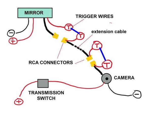
To spell it out even more... it's confusing that red wires appear to exit the connectors - they don't... it's just easier to make the cable that way. There are 3 wires in total in that cable:

1- video signal - between the centre of each connector.

2- video ground - between the outer ring of each connector.

3- a red wire - each end sticks out near the connectors.

Tom,  Here is what I see you need to do.

1. The camera needs power to operate and it will get its power from the Transmission Switch when you put your car in reverse.

2. The Mirror also needs power to operate hand gets it power from the separate + & - wires in your diagram.

3. Now you need to tell the mirror to tun on, so you need to connect the triggers wires together at each point so the mirro know to turn on.  See my diagram with the blue lines.  I am assuming the trigger wires send ground to the mirror to activate it.  The red wires I think are connected to the ground of the cable for the camera.

You can PM me if you need some more help.Back Up Camera

Attachments

Images (1)
  • Back Up Camera

The wires at the back up switch are a constant hot and a switched hot. You can confirm this by studying the SOBill diagram posted early in this thread

The red trigger wires do not carry a ground, they carry a +12 V.

It is best to tap into the back up light wiring in the tail light bucket area to make sure you are getting the switched tail light power, not the constant 12 V hot that goes to the switch.

Larry

Last edited by lf-tp2511

Add Reply

Post
×
×
×
×
Link copied to your clipboard.
×