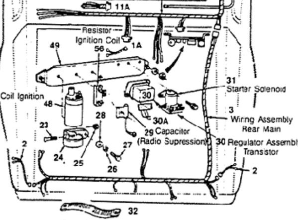
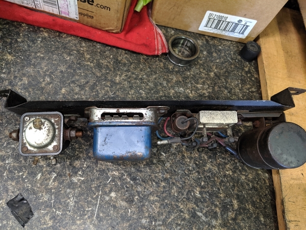
Could Someone post some pics of the electrical panels in their cars if poss. They are hard to see and I am working on mine and need a few different ideas? Stock/modified, etc. Thank you.
Replies sorted oldest to newest
hard to do a good picture..
- pretty much stock, still use the resitor...until the car runs as expected then turn to electronik
- the place where the resistor sits will be taken by a relais for the electric fuel pump...as soon I am ready
- also have several spare wires from the front for further instruments and fuel pump (you can see them on the right sdie in the picture, well I did a full wire loom overhaul all out on the bench - hope you do not want to do this..in case give me a PM.)
- From the regulator I added a decent BLACK wire to ground..(goes straight down from reg. to the chassis)
Attachments
Thank you! I saved this picture for future reference. I have found everything but the resistor. They come for sale on Ebay from time to time.
ok..well if you electronic no NEED
Taken through RH gill window
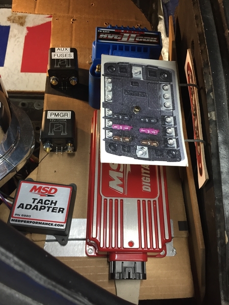
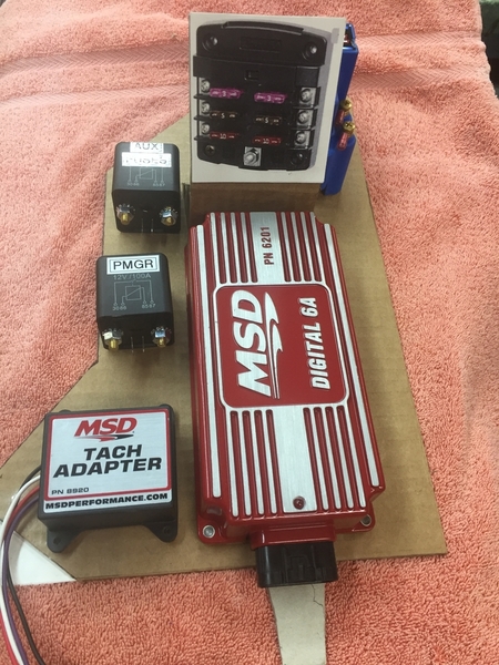
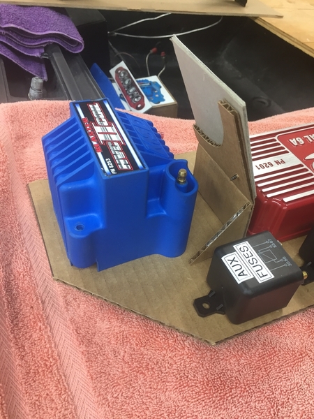 Now that she is home and basically an empty, rolling shell, 2511 offers the perfect opportunity to revamp the electrical panel and I have been making recent progress in that area.
While my layout is specific to my needs, I think the main take away from my approach is that I am fabricating a shelf in the original location so components can be accessed with just the removal of the engine covers, rather than from underneath and all the steps that approach requires.
Since I have a replacement PMGR starter, I am deleting the stock starter solenoid in favor of a smaller but amply-rated relay/solenoid.
I have also elected to install an auxiliary fuse block to power the engine management items. This will take some load off of the main fuse panel, always a good thing. This fuse block is powered through another high-amp relay which is triggered with the ignition switch start/run circuits.
Larry
First photo is an early mock up that has been deep-sixed, but it shows the area occupied by the shelf. Of note is that 2511 no longer has the charcoal canister and my coolant bottles have been relocated. Cars with stock located coolant bottles should have more room available.
Second and third photos are the current progression of the component layout.
Shelf will attach to firewall-mounted brackets with bolts and will be removable. Target goal is to have all but the high amperage circuits connected to the wire harness using multi pin connectors, so the entire component shelf can be assembled/removed for troubleshooting on a bench
Attachments
If you need an extra, stock bracket, I have one. ![]()
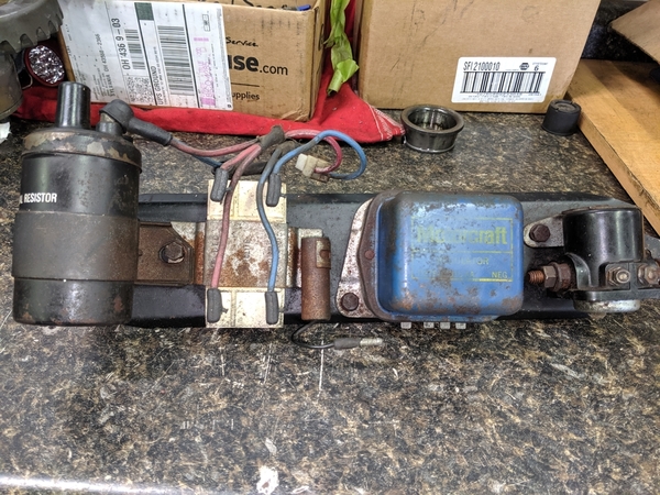
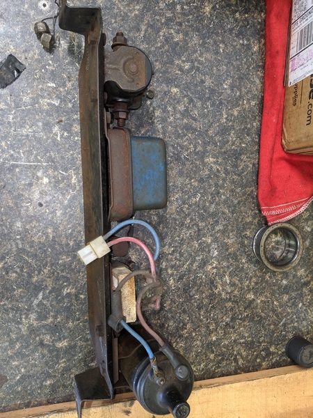
I may go electronic later, but for now, back to the basics.
Very helpful, thank you! Mine is very close to this one now. Your wires are different colors than mine are?
blkpntr posted:4Panteras posted:Could Someone post some pics of the electrical panels in their cars if poss. They are hard to see and I am working on mine and need a few different ideas? Stock/modified, etc. Thank you.
First time I've seen Panduit and terminal blocks used in a car. Nice. Great idea.


