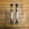
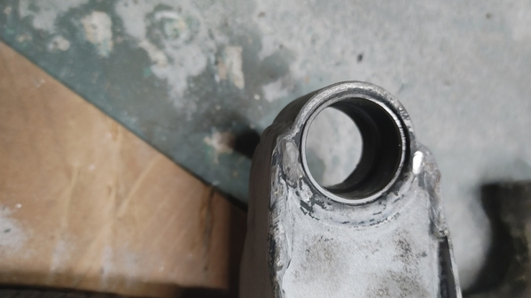
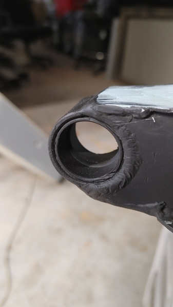
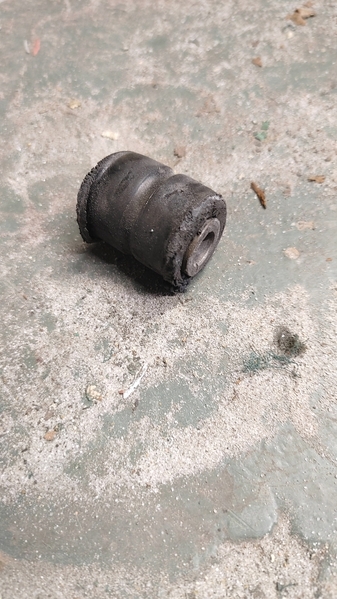
Rather than cutting the outer bushing end and retro-fitting a HEIM joint, wouldn't it be a better idea to find one pre-made to replace it with and bag-n-tag the original for posterity?

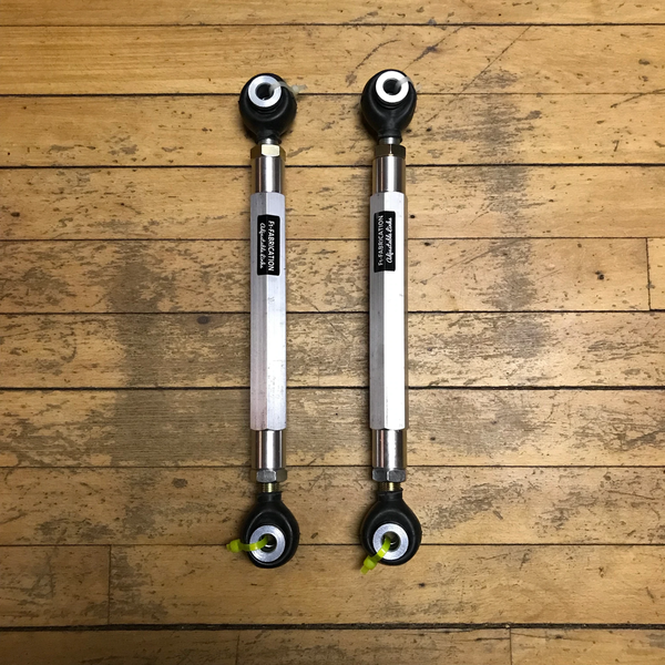
Something like this would seem to be a bolt-on solution:

https://f1-fabrication.myshopi...-300e-e320-400e-500e

image_2a64fdcc-06cb-446d-b3aa-1734e0972903_1024x1024@2x

There are of course MANY other companies that make them for custom chassis builders.


Thoughts?

MH

Attachments

Images (1)
  • image_2a64fdcc-06cb-446d-b3aa-1734e0972903_1024x1024@2x
Original Post

Replies sorted oldest to newest

When we were originally racing our car the guy preparing car did just that and I think he told me he used one clockwise and one counter clockwise joint so it was easy to adjust at track.  I’m seeing him tomorrow so will try to find out more.

as you say, lots of people providing the parts, not something you say often on a Mangusta!

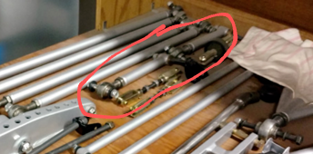
No, Sci-fi. A few years ago England's Johnny Woods noticed that the rear top link had only one heim joint. The other end of the link was a welded t-shaped tube with a bushing. Which bound up during suspension travel, producing rear bump-steer and seems to be the source of the oft-noticed "strange" handling. All the rest of the 'Goose rear suspension is a virtual copy of the 1964 GT-40 racer except for that link-end.

@scifi posted:

Thanks for the clarification. Yes, seems like a good idea. You save the original component and depending on your fab skills it may be the cheaper/easier route.

Now can you come up with an easy way to fix the rear top cross link?

The one that's soft mounted instead of welded and allows the chassis to hinge side to side.

I'm still thinking on that (Frame Bridge design)...  I recently pulled my engine and am restoring the engine bay & rear suspension while it's out...  which is why I'm looking at upgrades and such...  if I come up with a solution I'll be sure to post it for comments.

MH

I am no expert. The double heim would make adjustments certainly easier.  Later production Mangusta had gussets linking the bridge to the body. In my opinion preventing the body flex to over sway on brisk turns make the body & frame a whole.IMG_1994IMG_2039

Attachments

Images (2)
  • IMG_1994
  • IMG_2039
Last edited by denisc

When I was talking with Dick Ruzzin about changes we could make to our Mangusta (we originally planned to race it, but now have come to our senses and restoring as road car!) he was emphatic about the benefit of changes he made to the rear bridge that holds the ZF trans.  Basically the bridge was originally soft mounted via bushes to each side rail and the ZF is then solidly mounted.  This is round the wrong way.  So he decided to solidly mount the bridge and soft mount the trans.

Dick told me he could feel difference in a few hundred yards of driving the car. The bridge is removable to take the engine out.

He wrote an article on it which I will try and dig out but he definitely felt that the comments  the Mangusta received when released were down to this fundamental design flaw.  Combine that stiffness with the double Heim / Rose joint on the arms would improve everything while keeping the suspension settings constant.  When we did race our car for a short period of time (before we had a chance to do the mods, it was VERY lively at the back and often jin sideways over bumps under braking as you came on and off the power - very unpredictable!


hope that helps

Dick sent me an article but it's also published here (with comments / feedback from others).  

I can't seem to paste the weblink, but if you search the Forum for Mangusta Handling Mystery by Dick it's all there including photos.  

If you are into upgrades I had a quicker steering rack made here in UK by a race company to fit (with a tiny bit of fabrication) which provides much faster response without making steering too heavy . About 2.5 turns lock to lock but they can make it to any ration you want.  I own the design drawing but your welcome to use it if you want.  I paid £500 plus shipping.  

Cheers

Larry  

M!ke, seems like a pretty simple way to try the "full heim" solution. At least, its probably smart to avoid cutting the originals, but also anybody that would decide to cut the original and weld in an insert will probably be smarter to buy 2 inserts and new metal tubing to make them completely from scratch).

  The gusset that Denis points to was added in quite late, somewhere between 8ma1046 (that didn't have these, but coincidentally still had aluminum calipers) and 8ma1074 at least (that were on cast iron brake calipers and had the gusset)...Lee

ps. see this earlier thread by Dick, just noting to replace the bushings themselves in the bridge https://pantera.infopop.cc/top...ruzzindesign-aol-com

Last edited by leea

In my opinion put the rear bridge re-design on hold. A lower cost option would be to clone the rear uppers with double ended heim joints (use identical size and brand and materials and make one end LH thread) and add the frame to body gussets and repace the tired / worn bridge bushings. 99.9% of car guys and 99% of car show judges wont know the difference (maybe 6 of us here on this forum may notice...after 10 minutes)

The bridge re-design will definately cost more and stand-out as a modification and I personnaly am not sure you will see a difference.

I have driven over 17,250 km (10,000 miles) not often at low speeds and cannot say I have experienced simutaneaous over under/oversteer as in the original Sports Car Graphic article.

Last edited by denisc

That "bridge" mount for the ZF was an extension of the theme that DeTomaso tried for when adapting the P-5000 sports-racer chassis to the Mangusta body. The Mangusta was envisioned as a 'Gentleman's Express,' not a raw racing car, hence a quieter shock-mounting of the transaxle instead of a better rigid mount, sound-proofing everywhere- even inside the doors, an absorbent  drip tray below the master cylinders to protect the driver's pants from random fluid drips and even a factory-supplied 'wiping cloth' in the tool kit! The car was supposed to be elegant, not a noisy, rough-edged racer.

Larry and Jack, there are a couple things about these drawings that interest me...

   -Jack,  interesting that only the very first few Mangustas seemed to have silentblocks on the front suspension...and afterwards, at least on the suspension just a thin skin of polyurethane bushing  (when silentblock isolation was standard on the Maserati GTs..). But overall, hard to get less cushy than a Mangusta, I'd think...

- Larry, yeah, the pictures here in the parts book seemed to be by a cartoonist (here is an isometric picture of a nut...). The 'Silvestro leaks' show that DeT made or kept their own drawings even for parts they may have completely leveraged (eg DeCarbon shock here...even if it does show the shock is red, which nobody has seen!), even if they didn't get someone who would write text very clearly...

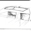
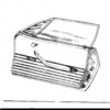
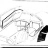
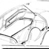
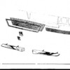
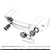
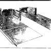
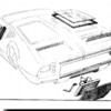
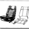
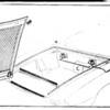
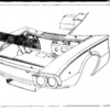
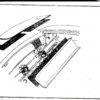
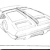
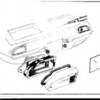
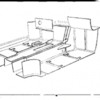
But Larry and Jack, where did -these- body pictures come from? I think I pulled them off the Mangusta International site 2 decades ago, and given their thumbnail sizes there were probably posted with a dialup modem.... But any idea what document these came from? Lee

Attachments

Images (21)
  • Silentblock from 8ma502 to 514 or 518 only
  • mceclip0
  • mceclip1
  • mceclip4
  • mceclip2
  • mceclip3
  • mceclip5
  • mceclip6
  • mceclip7
  • mceclip8
  • mceclip9
  • mceclip10
  • mceclip12
  • mceclip13
  • mceclip14
  • mceclip15
  • mceclip16
  • mceclip17
  • mceclip18
  • mceclip11
  • Mangusta decarbon shock absorber
Last edited by leea

Those hand-drawn images came from what passes for a Shop Manual or Parts Listing for Mangustas. I've seen two versions- one has more pages than the other. Vallelungas are almost the same. As far as background, DeTomaso only introduced U.S- type shop manuals and Parts Lists with actual photos when Ford got involved in the company in 1971, unfortunately too late for the Goose..

@leea posted:

Scifi, do you remember what the replacement bushing is?

No... I bought a 'make your own bushing' kit.  Then, as I was not even working on that project, came upon some leftover shock bushings from the front of the car which fit perfectly! Likely this a bog standard shock bushing you could find at any auto parts store. Note that the re-install is more challenging than disassembly. You might need a floor jack, a friend and some WD40 because once you have fresh rubber in there, it takes some wrangling to get all the bolts re-installed.

@mkeh posted:

Well, that explains why they won't come out!

I don't see any way that it's welded in place, mist be heat fitted or used some sort of adhesive...

Thanks,

MH

I tried to remove them too! No amount of beating seemed to help so I simply convinced myself they are meant to stay. No trouble since then. Things feel much more solid. Old bushings had turned to dust.

Last edited by scifi
@leea posted:

But Larry and Jack, where did -these- body pictures come from? I think I pulled them off the Mangusta International site 2 decades ago, and given their thumbnail sizes there were probably posted with a dialup modem.... But any idea what document these came from? Lee
My understanding of the parts (exploded view) documents, there are two parts manuals. One manual produced by Ghia for the coach parts. The second manual was produced by De Tomaso for the chassis parts.

We have reproduced what I believe is an early version of Ghia's coach parts manual. The thumbnails above have pictures among them which are not in our manual, I believe it must be a later example. For instance, our manual had the fiberglass bucket style seats, the thumbnails above have a picture of the metal frame seats.

-G

George, thanks---I have a copy of the reproduction, it’s a beautiful reconstruction and an incredible amount of work…But I think must be a third document that (except for thumbnails) appears to be lost to history, Esp;

* The pictures in the thumbnails are high quality, not close to the simple pictures in the Detomaso parts guide.
* The thumbnails are way too sparse to have been a parts book—for example, the “Door Assembly” or T-wing Rib” could hardly be assumed to be used as a spares guide. And of course, no number designators anywhere…or what appears to be rear bumpers grouped in the “front grille” portion.
* The date had to precede the DeT parts book---or at least, the rather complete drawing of the 2 piece seats vs. single piece buckets.

I’m just guessing these were design elements provided to Ghia, and assume that DeT or Ghia had another cycle where they converted these to engineering documents. But as the song of that time goes, ‘the answer my friend…...” 😊 Lee

Add Reply

Post
×
×
×
×
Link copied to your clipboard.
×