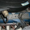
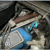
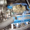
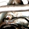
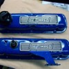
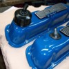
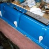
I just cleaned up a nice pair of original Goose valve covers....and need a tad bit of help.

Can anyone recommend their solution to gluing down the aluminum emblems to the original style of valve covers?????

How did you do it so that you didn't have adhesive running all over.....???

(See more related questions below!)
Thanks!
Steve
Last edited {1}
Original Post

Replies sorted oldest to newest

I’ve wondered about the best method for doing this as well Steve and I think when I do mine I’ll be looking at some of the industrial (not the store grade stuff) epoxies. Mounting the plates to the valve covers when they are off the car should avoid too much of a mess. I plan to roughen the VC surface to improve adhesion. I don't know if the epoxy would work but I'm not confident that silicone would work based on my past experiences with it on other things.

Unfortunately the backs of the roughly cast plates and the embossed Ford valve covers do not provide the ideal flat, smooth surfaces that a foam-tape would need to work effectively. I think also the oil and heat present in the engine bay might eventually work away at the tape edges unless the parts were both machined flat and mated smoothly. Then I’d put money on the 3M VHB outlasting most other solutions.
Steve, you know its hard to beat the mechanical security of screws and locking (NOT Nylok!) nuts. Countersink flathead screws with Devcon or JB-Weld filling the screw holes, then filed off makes for a simple, almost invisible fix- especially if you finish the job with a spritz of appropriate color rattle-can paint. One screw per emblem should do it. 250 degree F running oil temp and differential heat expansion (glue vs aluminum or steel) will likely keep any glue from guaranteeing a permanent hold. And Goose plaques are expensive!
OK, another valve cover question!

I know that on the air injection engines (smog pump!) the spark plug tabs on the V/C's were fitted with the factory "extensions" to keep plug wires off of the hot air injection rails.

If you did NOT have air injection, did those extensions still get used?????

I can't find enough pictures to see a trend at all. Those extensions were only used on 1968 engines AFAIK! 69 engines generally didn't have air injection on production Mustangs, only with the Boss2 and the 428CJ.

I want to put my emblems on.....but need to understand if I should or shouldn't put the extensions in place!

A good picture of a LH (driver) side extension would be nice too! I only have pic's of a RH version....and only a RH version in my possession!

Pics of attaching screws would be nice.

Once the emblems are attached, it appears like there isn't enough room to slip the stock plastic wire organizer/retainer in place????

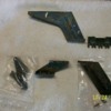
In pic below, top bracket is for RH V/C, correct for Goose.
LH bottom is a 67 410 version, RH bottom is a 66 Lincoln 430 version.

I would like to know if either on the bottom are close to proper for LH V/C??? (or was one even used?)
Cheers!
Steve

Attachments

Images (1)
  • 101_6156
Last edited by mangusta
Rich,
If you have a RHD car, then "who knows" reigns supreme! By late 70-71, who knows what engines Ford was sending DeT!

Looks good though!

What you are missing (perhaps!) is the small bent up piece of tin that holds the wires off of the jackshaft. It looks like you have an aftermarket intake (hidden in blue!) so you actually may not have the provision to mount it!

I ran into that with my Edelbrock.... Frowner

Steve

Attachments

Images (1)
  • wireholder2
Ok Steve now I get you, that makes sense. My car is left hand drive, but when I got it there were original parts missing, the engine has been modified from original which I had tested over here on a dyno - not in the car, it is producing a tad over 340hp. We thought of putting original headers back on and Johnny made up a pair of beautiful, hand beaten heat shields. But then we decided that the big bore headers and exhaust had been made so well and that the original headers would have stifled the engine, we went with what I have got! Also we ran out of time and to get these made because we had entered the car into the annual indoor classic and sports car show.

I still need to source parts for the AC compressor, the suction side originally had an extended service/shut off valve that I don't have, it had a 1/4" link pipe connecting to the discharge service valve.

Roger Brotton has three Mangusta's at his workshop all from the USA and one I know of is very original so I will check with him next week when I visit and let you know what I find.

Johnny is going to do another rebuild article shortly on my car so I hope you find that of interest when he posts it.

Regards Richard.
OK, mastic sounds like a nice search objective!

I've also got a tube of "automotive" silicon, which I have used on various bits in the past, normally as sealer, but also to hold window glass in their channels. But it must be "automotive"! Bath tub and tile won't cut it!

Alrighty, one more question related to the stock Ford extensions that are fastened to the covers to keep the wires off of the air tubes......

What size are the small screws? They appear in one picture that someone posted on another thread, to be oval head, about 10mm long. Hole in the small bracket on the V/C is 3mm. If memory serves me...some have nuts.....some like the picture from the post about engine compartments, appear to not have nuts.....

The stock fasteners were self tapping hex heads (1/4 or 5/16" head) about 5/16" long as seen in my pic above.

I'm guessing that DeT workers disassembled the pieces when they welded the small tab in place for the throttle return spring, for them to repaint it, and likely lost the screws.....and grabbed what they could find to "git er done!"

Cheers!
Steve
Simon,

On the OLD Mangustas, that was one of your heater control valves.

There were two, one on each side, and typically, those connections that you see where an actuator cable might go, were left empty! This required a Chinese fire drill at some convenient location every time someone wanted the heat on....or off....or on....

Not a well thought out aspect of the car details and apparently not one that concerned DeT too much in that the factory shipped hundreds of cars this way.

I believe that the Germans who built the last round of cars actually took the time to run cables up to the front somewhere......

The water valves that you see have a tendency to rot apart badly....even in the Fiats that they were originally sourced from....making them a tough piece to find!

Since my water valves were never on the car when I got it.....I had no idea what I was missing...had another completely different bag of troubles!

Short story is that I connected two ball valves in the passenger compartment, one on each side of the top of the center spine, behind the console top area, where I can just barely reach them. I leave the RH one cracked just a small amount, and then modulate temp quantity with the LH valve, which I can reach from the driver's seat with a minor amount of distortion..... If I was to ever blow out the heater core or blow a hose portion, I can easily shut both valves down.

The ONLY thing you need to be aware of in doing this, is that you need to install a small bypass hose somewhere, between the two heater lines, before the shut off valves. This provision allows for air bubbles to travel thru the system, out of the water pump, which is where they would collect without the bypass. Don't ask how I know this.....

The original configuration had this provision accounted for.

Cheers!
Steve
Ahh yes, the ol' thermostatic valve with absolutely nothing connected to it on the inside of the air cleaner!

I think I have one of those air cleaners on my shelf!

I think Lee(?) posted the pics of this car over on the "pictures of (original?) engine compartments" post.

Good shots of a largely unmolested engine....except of course the spark plug wires......Motorcraft wires would never be stock on a Goose.

Steve
Hi Steve, just thought I would mention what I did re my valve cover logos.
Mine were glued on with what looked like araldite, running everywhere.
When I refitted them I drilled from inside the valve cover, and part way through the casting, then blind tapped them 1/8" whit.
When I fitted them I used the adhesive silicone in a few spots, with a very small amount of loctite on the metal threads.

Also with the plug leads, mine has the original nylon strips that separate the leads, and the front right one slips inside the sheet metal strip bracket to keep them off the shaft as well as clear of anything that they may short on.
Regards Terry

Attachments

Images (1)
  • 302_8ma_1298
Steve,
Intake casting no? is "8ZE-9425-A" not sure what date that is?
Block number is "OA10" which is 10th Jan 1970?
Heads "OA20" which is 20th Jan 1970?
And the headers have I think been worked on, but there is no evidence of any shields being fitted.
A letter I got years ago from Claudia Lodi said my car was built in 1972.
Regards

Terry
OK, thanks.
I couldn't make the numbers out in the pic as posted.

Yes, 0A10= Jan 10, 70. Still not something we see very often! With the heads being only 10 days off, if the intake is in there somewhere, you'd have the trifecta of casting dates!

C8ZE-9425-A is indeed the casting number. 4 digit intake date should be right there on the top too..... down by the distributor..I can see it but can't read it!

1972...wow. I always presumed that 71 would have been last of the last!
Thanks!!!
Steve
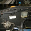
OK, finally got my V/C's painted half decent. Put the wire holder extension in place with stock screws.

Modified the black 6mm wire holders to bolt them to the 9mm Ford Racing holders to put them in the stock location. LH looks like it should work fine, RH may have a problem....wires seem shorter on that side!

Used black "automotive silicon" sealer to adhere the emblems to the covers. So far so good.

Put the gaskets on the V/C's last night with gasket sealer, and used silicon sealer tube caps to center the mounting holes properly! Worked like a champ! (Have always wanted to find a use for all of those damned things collecting in my sealer drawer......

Pictures.... will probably have to post these in a series of posts.

Attachments

Images (1)
  • 101_6333_(Large)
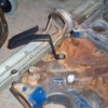
End view. Oil filler cap is late 69 to 1970 type with plastic hose fitting. Proper 68 69 part is a steel block type as seen in other photos. Didn't have one of them handy........so this will do for now.

I fab'd the tab adjacent to the PCV valve for the throttle return spring.... unused in some cars after either the factory put the carbs back on normal orientation, or owners did.
Steve

Attachments

Images (1)
  • 101_6335_(Large)
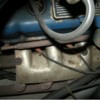
Tube caps holding gaskets in place until sealer can set up.

I then set these on top of a valve cover spacer that I do not believe I need to use any longer for rocker arm clearance.....if my measurements serve me properly! This allowed the tips of the caps to fit down in as far as possible and also to provide a flat surface on which the entire gasket surface can press against.

I then covered the V/C with a thick towel, and put about 25lbs of old barbell weights on top to apply some pressure to even out the sealer.... left it about 30-45 minutes and once set, set them aside for assembly hopefully later today!

Cheers!
Steve

Attachments

Images (1)
  • 101_6341_(Large)
Steve, btw, the water valves are easy--Alfa Giulia, less than $70 each new...still. The strange thing to me is the mounting--if the left and right brackets are swapped, the hose routing is a straight shot forward (the hose doesn't have to first route towards the rear of the car before turning forward...). who knows why...Lee
Lee,

That's good news for all to hear!!!!

Last I knew, the valves were "Fiat" parts and the world had snapped up all of the spares in existence! Perhaps Alfa did the Fiat world a favor and put them back into production.....?....

I never got the brackets for the valves with my car, removed long before me! Since I put the "T's" in the lines and used a small 3/8" or so crossover line (between where the two switches would go) to do the same thing, AND put my shut off valves up on top of the center spine behind the defroster/heater core assy, I'm not sure I would go thru the clutter.....to make something like that functional again!

Perhaps put two new water valves in the "Goose parts" box I have and let the next caretaker deal with it..... Smiler Smiler Smiler !!!

Hopefully tomorrow will be a dry day to work on the car with the garage door open...and get these valve covers back in place!!!!

Ciao!
Steve

Add Reply

Post
×
×
×
×
Link copied to your clipboard.
×