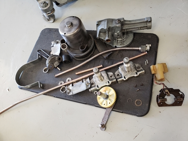
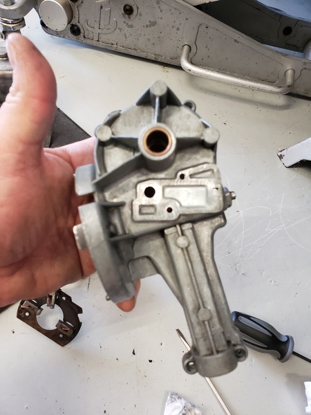
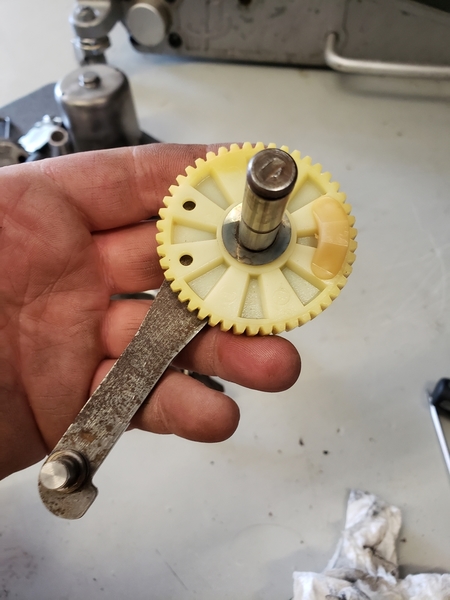
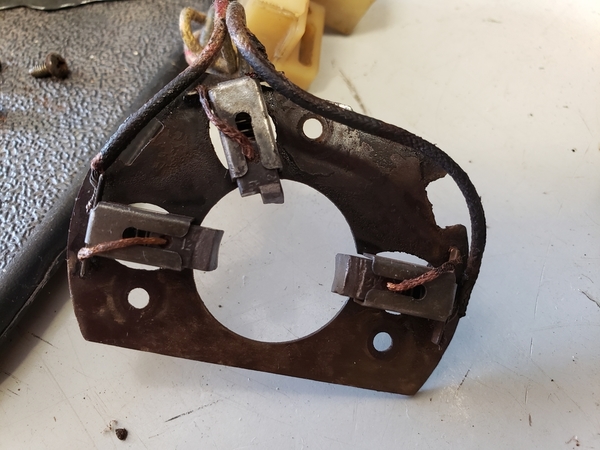
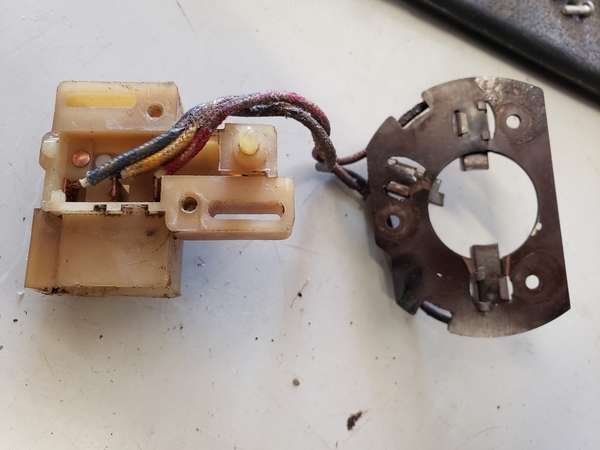
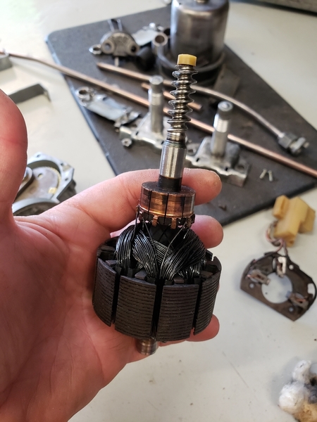
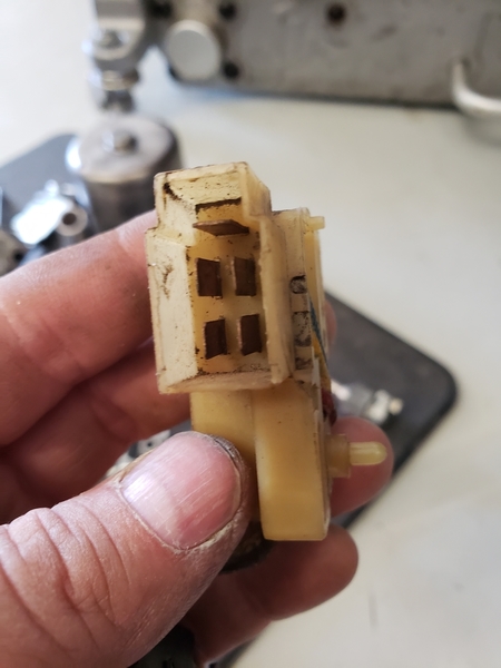
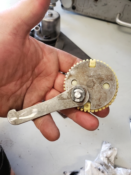
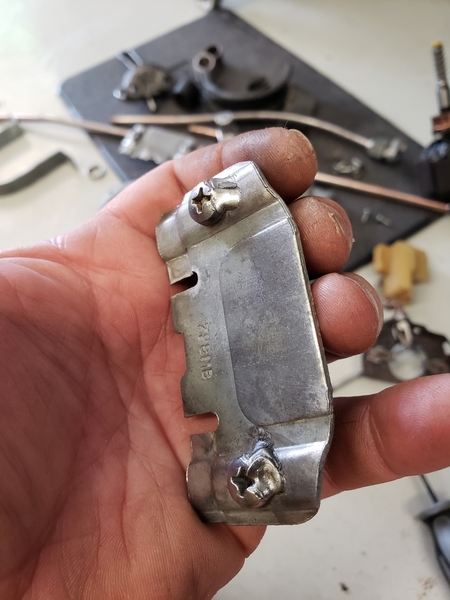
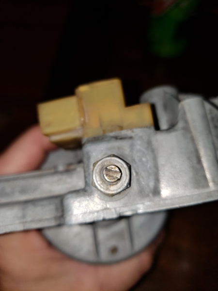
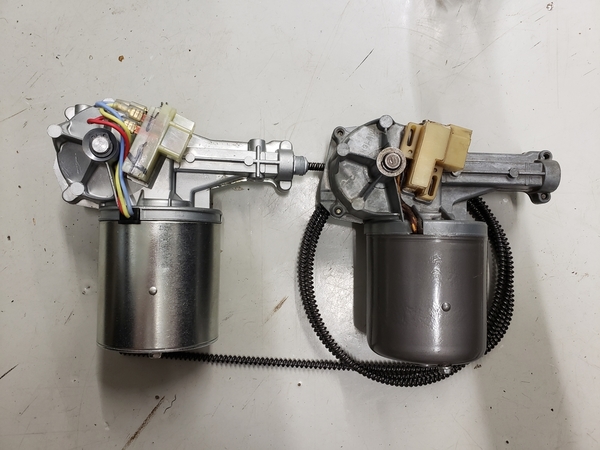
What is the secret to removing the cable assembly from the wiper motor? It is attached with a nut threading onto the motor housing. Once the nut is removed, the cable assembly still does not want to come off.
Replies sorted oldest to newest
Steve
http://www.specialtypowerwindows.com/products.php?c=2

Thanks
quote:What is the secret to removing the cable assembly from the wiper motor? It is attached with a nut threading onto the motor housing. Once the nut is removed, the cable assembly still does not want to come off.
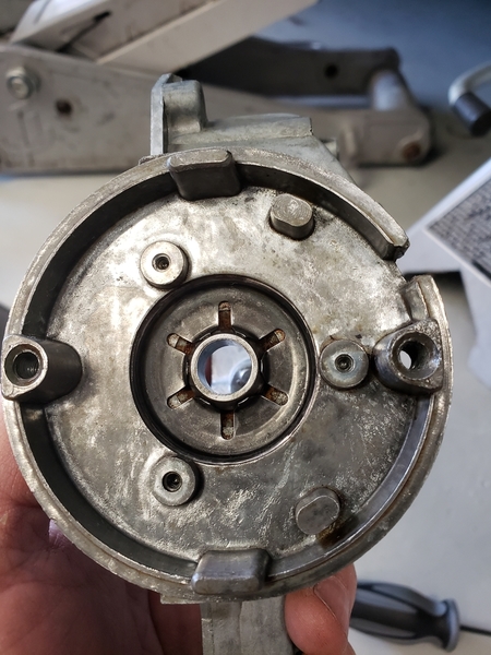
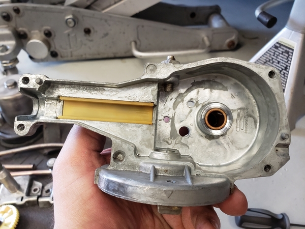
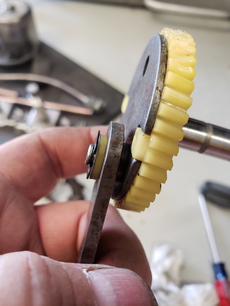
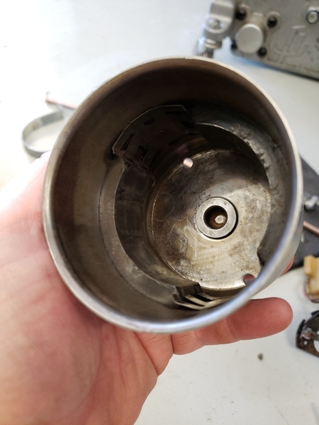
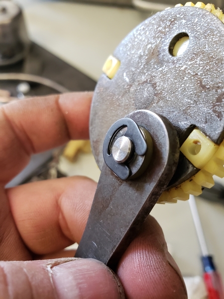
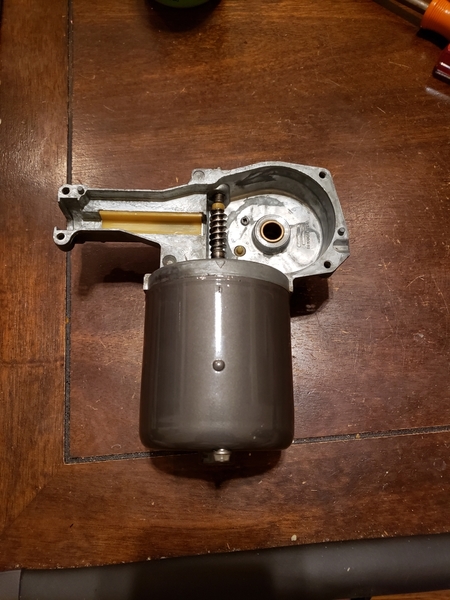
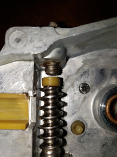
On the picture you see the inside of the motor, the cable assembly/"push rod" is fixed by the lid/motor cover per 4 screws, and adjusted per the big nut at the end.
Not sure if you can take the MOTOR out and leave the cable/Push rod in place. I removed everything for overhaul.
What T. Solo is saying is probably the best. Get the Wiper arms off..per a small piece of wood used as lever. Then you can pull everything out motor incl the push rod/Cable assembly. The wiper studs stay in place. Same way to get it back in.
Pic 1
Attachments
Thanks for the updates and the pictures in this thread...
Searching just saved me from asking again (and having to wait). Now I can keep working.
What type of metal are the wiper tubes made of?
It looked like copper to me so I was just going to polish it up, leave it bare, and polish it again whenever I decided it was time.
However, when removing the paint that was on it, the copper seemed to at least partially go with it as the finish turned silver. Did I take off a copper coating on some other type of metal?
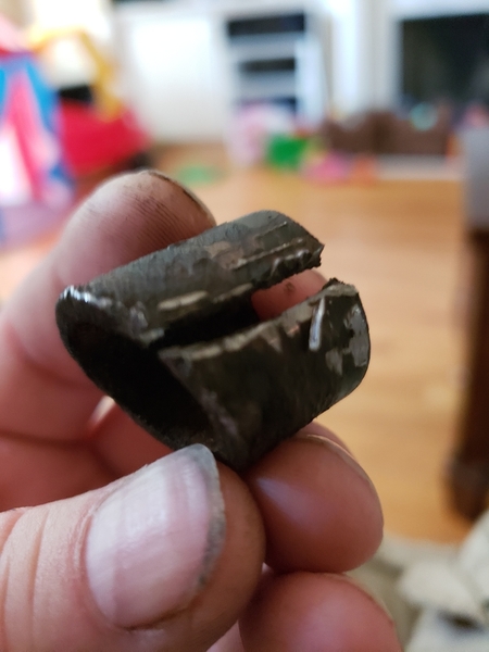
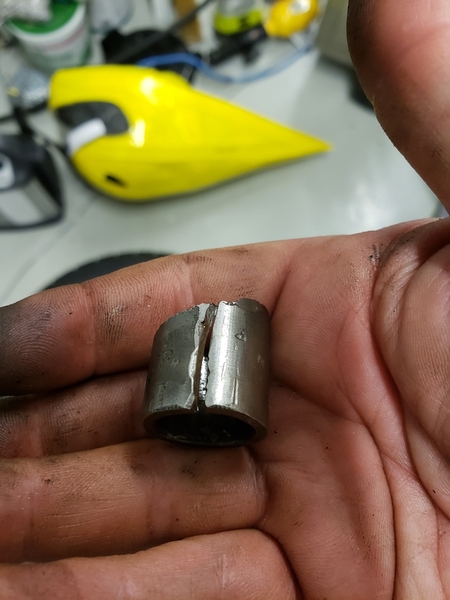
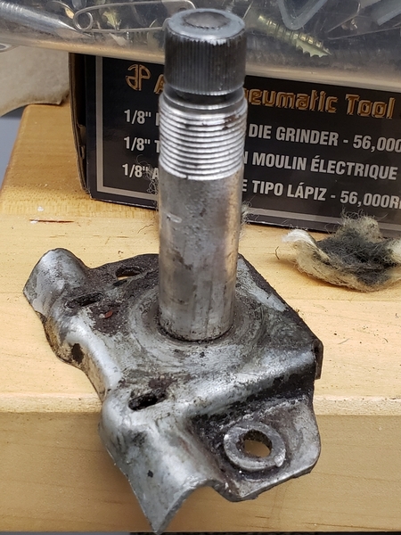
Anybody ever have the angled steel sleeve that sits behind the chrome nut rust to the wiper pivot?
Mine did on the driver's side and it isn't coming off.
I put PB blaster on it, pried, hit it with a hammer harder than I should have, twisted - to the point that I think I detached the pivot shaft from the base.
I hit it with some more PB blaster to let it sit overnight, but I may have to consider a cutoff wheel - which is not going to be fun given how thick that sleeve is.
I ended up being forced to take a dremel with a cut off wheel on that upper spacer.
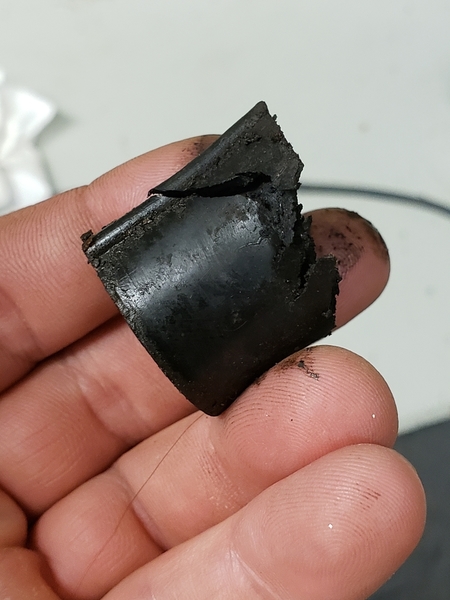
As part of my earlier attempts to remove the upper spacer I damaged the lower spacer which on my car ('71) was rubber. The replacements I see online are metal, e.g., https://panterapartsusa.myshop...pers/products/17007a
Does anyone sell rubber versions?
I also had to destroy a wiper spacer to remove one that was galvanized in place. I purchased a replacement through a vendor and in hindsight wish I had simply bought an appropriate diameter hollow aluminum rod on line and cut it to match the length and required angle. That was what the vendor had done with the replacement piece that I was provided. Lesson learned
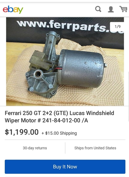
Also, I discovered that you can by a complete wiper system here for less than $200 - that's a bargain in the land of Pantera parts. (I think I found that on this forum in another wiper thread.)
I don't know if the angle is correct, but it looks like Mini Coopers used the same setup and had rubber lower spacers...
perryh posted:Also, I discovered that you can by a complete wiper system here for less than $200 - that's a bargain in the land of Pantera parts. (I think I found that on this forum in another wiper thread.)
I replaced my complete system with this system, and it worked fine driving in the rain for about 8 hours on one day last summer. I specified a gear with 5 degrees more sweep, and it covers the windscreen nicely. I used my original tubes for the long flexible shaft to run in, rather than the ones supplied, because I couldn't bend them (they come straight in the kit) without compressing them too much. I also used the original spacers on the shafts that the windscreen wipers attach to, as the ones in the kit had the wrong angle on the bottom.
Cheers, Tim.
I found a Lucas part number on the rubber lower sleeve. Lucas calls it a bushing, sometimes abbreviating it as bush, and refers to it as a rear bushing.
The part number is 744983. It seems these were used on some Jags and Lotuses (Loti?). However, after looking at photos of the part online it looks like the ones on my car were modified either at the DeTomaso factory or by a previous owner to both change the angle and make them shorter. The flat surface, perpendicular to the cylinder was not cut. That is where the part number is. The angled surface was cut - perhaps by a bandsaw.
I think the purpose of the screw on top of the motor housing is to adjust the position of the rotor commutator in relation to the carbon brushes. I had the same prob with one of my radiator fan motor. If not adjusted correctly the brushes will rub (and wear out) against the small studs which contact the commutator fields with the windings.
perryh posted:
From a Lucas repair manual
Adjust armature end float
.
"To check armature end float when a non adjustable thrust screw is fitted perform the following operation.
Position a feeler gauge between armature shaft and thrust screw. Push armature towards cover.
End float should be 0.002-0.008 in.
In the unlikely event of adjustment being required end float may be increased by fitting shim washer/washers under thrust screw head or reduced by mounting thrust screw in lathe and removing metal from underside of head.
If a service replacement armature is fitted it should be supplied with an adjustable thrust screw and lock nut as a boxing sundry.
To adjust armature end float when an adjustable thm.st screw and lock nut is fitted perform the following operation.
Slacken lock nut.
Screw thrust screw in until resistance is felt. Screw thrust screw out quarter of a turn—maintain in this position and tighten lock nut.
Thus I would assume, the position of the cover bearing should set the commutator to brushes AND put the armature in the center of the stator. then the "screw" set the thrust end play
perryh posted:
When I see the copper wiring on your electric motor anchor I think it's better to replace this .
The dark wiring must be copper colored, I think yours was too hot and burned .
maybe you can smells the burned wiring too.
Better is to replace the anchor , or maybe better the whole wipermotor by a (not expensive) aftermarket piece.
This is just my experience over the years.
Simon
I thought that too, but after I looked more closely, I don't think it burned.
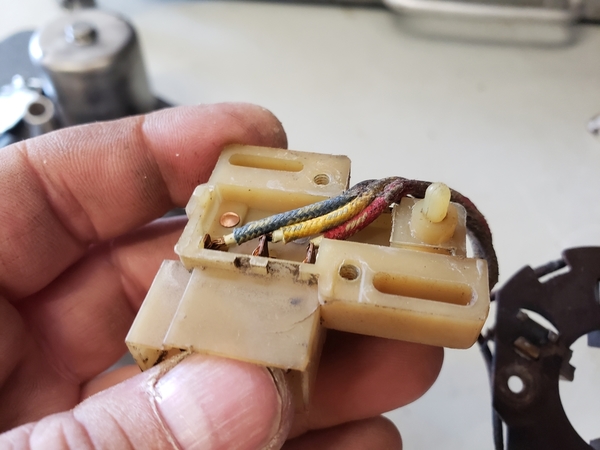
I think that is 40 years of carbon dust from the brushes arcing and being deposited on the wires. The piece of fiber board that the brushes are mounted on was similarly coated. I could not get it off of the wires without risking removal of their insulation.
The motor does run. I partially reassembled it and tested it last night.
Warning and wisdom noted however. I will consider whether to heed it. I would not be so much worried about having to take it back apart (that's easy now that I know how). It is potentially setting my car on fire with some crappy old motor.
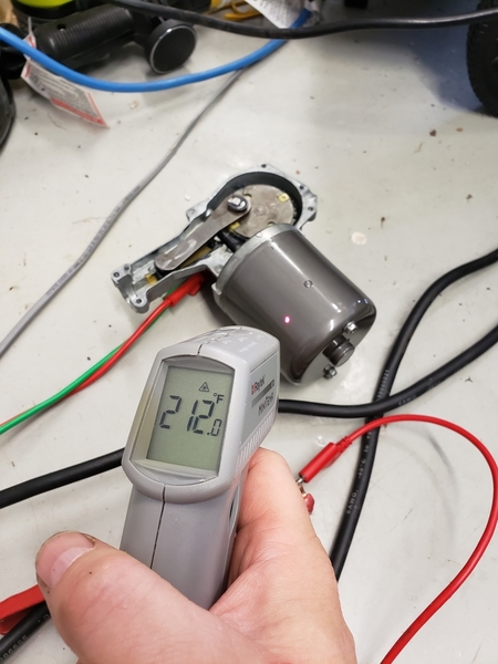
I am guessing this isn't right... ![]() unless loading the motor is needed to pull the rotor into a more electrically efficient position.
unless loading the motor is needed to pull the rotor into a more electrically efficient position.
It would have just kept going up, and I don't know how much current it was pulling. I'll stick an ammeter in series to see.
Edit - between 7 and 8 amps (I think in the high speed mode).


