quote:
Originally posted by forestg:
George,
What's involved in changing to the EDIS ignition?
Thanks,
Forest
Hi Forest
I'll begin with an overview of the evolution of Ford's ignitions
Distributor ignitions (one coil)
Ford's distributor based ignition systems progressed from breaker point ignitions, to the first "breakerless" (Duraspark) ignitions and finally to the "TFI" ignitions. These distributor based ignitions fired their single ignition coil 4 times per crankshaft revolution, each spark plug was fired once per two revolutions of the crankshaft. Breakerless ignition triggering was accomplished with a 1-1/2 inch diameter reluctor (aka an armature) having 8 teeth (assuming we’re talking about a V8 engine) mounted inside a distributor. An 8 tooth reluctor turning at distributor speed (half the speed of the crankshaft) equated to one tooth for every 90 crankshaft degrees. Very small misalignment of the reluctor teeth impacted ignition timing by several degrees due to the small diameter of the reluctor. The magnetic sensor of the first "breakerless" (Duraspark) ignitions created a rather inaccurate "sine wave" signal for triggering the ignition, whereas the sensor of the TFI ignition created a more accurate "square wave" triggering signal. The distributor based triggering systems were all subject to drift over time as the camshaft timing chain stretched. You folks who are interested in ignitions employing a distributor and one coil, I've covered that topic in the 351C sticky (sticky #3).
EDIS Ignition (one coil per two cylinders)
In the mid-1980s the North American auto manufacturers upgraded the ignitions of their motors from systems employing a distributor and one ignition coil to wasted spark distributorless ignitions employing crankshaft mounted triggering systems and four coils. This move was motivated by ever tightening emissions legislation and the EPA requirement for the auto manufacturers to warrantee their emissions control systems for 100,000 miles.
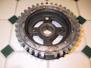
Ford’s first distributorless ignition was called the Electronic Distributorless Ignition System (EDIS). It was a “wasted spark” system which means there was one coil for every two cylinders. Each coil fired once per revolution of the crankshaft, igniting the mixture in one cylinder near the beginning of the power stroke and simultaneously firing the spark plug in another cylinder during its exhaust stroke. Spark plugs wore out at twice the speed of other ignitions however because each spark plug fired once for every revolution of the crankshaft. The system was triggered via a crankshaft mounted trigger wheel which was approximately 6 inches in diameter and having 36 teeth. Thirty six teeth on a six inch diameter crankshaft mounted trigger wheel equated to one tooth on the trigger wheel precisely every 10 crankshaft degrees, thus providing far greater ignition timing precision. The triggering system was not subject to drift because the trigger wheel was mounted directly to the crankshaft.
The triggering system reduced emissions because it more precisely fired the ignition coils each and every revolution of the crankshaft and the ignition timing was more consistent from cylinder to cylinder. Unlike single coil distributor ignitions in which performance falls off at high RPM an EDIS ignition provides full spark energy at any real-world engine speed. With the EDIS ignition there was no spark scatter and reduced misfiring. The EDIS ignition also allowed the Engine Management Computer to control the functions of the ignition which allowed ignition timing to be controlled using an array of engine sensors as inputs, multiple tables could be stored for various scenarios, and adaptive programming allowed the engine management system to modify the tables and adapt itself to various operating conditions.
The EDIS ignition system aided Ford in warranting their emissions system for 100,000 miles because all of the timing functions were set electronically and could theoretically operate perfectly forever. There was nothing mechanical to wear out or service, no centrifugal advance mechanism to re-curve or wear out, no distributor cap and rotor to replace, it had no moving parts whatsoever. The only parts that deteriorated with use were the spark plug wires and the spark plugs.
Coil On Plug Ignition (one coil per cylinder)
In the mid-1990s the EPA gave a new mandate to the automakers, to provide the engine management systems with the ability to monitor and record misfires. Reducing misfires seems to be the motivation behind the North American auto manufacturer’s move away from wasted spark ignition to individual coil ignition in the mid-1990s. Whereas the move from distributor based ignitions to distributorless ignitions required the adaptation of entirely new ignition systems, the move to individual coils was merely an upgrade of the distributorless systems that had been in production for over a decade. Even so, this upgrade made it possible to greatly enhance the performance, features and functionality of the ignitions. The manufacturers consider their individual coil ignitions to be as superior to wasted spark ignition as wasted spark ignitions were superior to ignitions employing distributors and single coils. However, most of the advantages relate to igniting the mixtures of "near zero emissions" engines, complimenting engine management systems that monitor each cylinder for misfires, and achieving better ignition performance over a 100,000 mile service interval.
Coil On Plug (COP) systems are the norm for overhead cam motors, such as Ford’s modular V8, for a number of packaging, performance, emissions and maintenance reasons. Individual COP ignition coils are mounted on the valve covers directly over each spark plug, and reach down through the valve cover recesses with a short rubber “neck” to make connection with the spark plugs.
However, GM had to utilize a Coil-Near-Plug (CNP) system for their LS series OHV motors because there wasn't space to mount a coil on the end of each plug and exhaust system heat would have shortened the life of the coils, or required expensive heat protective packaging. GM’s individual coils are mounted on the valve cover and attached to the plugs by short spark plug wires.
The OEMs universally disliked spark plug wires, and were glad to either get rid of them or (as in the case of GM’s LS series engines) shorten them. Spark plug wires were bulky, expensive and cumbersome to route around an engine. Spark plug wires were a source of radio frequency interference that sometimes compromised the operation of the on-board engine computers. Eliminating spark plug wires eliminated potential misfire problems caused by burned, chaffed or loose cables, and reduced the resistance along the path between the coil and the plug. Consequently, each coil could be smaller, lighter and use less energy to fire its spark plug; which is why Ford’s COP coils are physically smaller than GM’s CNP coils.
The same crankshaft trigger wheel that was employed for wasted spark ignitions is employed for the individual coil ignitions too; but since individual coil ignitions only fire the spark plugs once for every two revolutions of the crankshaft, a second “camshaft position sensor” must also be employed.
I mentioned previously that the only parts that deteriorated in a wasted spark ignition were the spark plug wires and the spark plugs. COP style individual coil ignitions eliminate the spark plug wires, and since individual coil ignitions fire the spark plugs only half as often, the condition of the spark plugs deteriorates at half the speed!
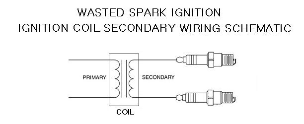
Wasted spark ignition systems connect the dual “paired” spark plugs to the secondary of one coil in a manner wherein the high tension leads and the spark plugs of “paired” cylinders are in series with each other and the secondary windings of the coil; when the coil fires the spark has to jump the gap of both plugs. Both spark plugs have to fire or neither of them shall fire. If one cylinder is running poorly the cylinder it is “paired” with via the ignition shall run poorly too. Elimination of this possibility is another benefit of individual coil ignitions.
Individual coil ignition enables the Engine Management System to monitor the ignition for each cylinder individually and control the charging of the coil for each cylinder individually also. This means each coil can be charged to meet the unique operating conditions of the cylinder it is associated with. Since coil charging time is doubled with individual coil ignition (compared to wasted spark ignition) the engine management system is enabled to make ignition adjustments between cylinder firings which make individual coil ignitions very quick at responding to changing engine loads and driving conditions; this also allows the coil’s saturation to be controlled to a higher degree, leading to vastly improved ignition of the mixture within each cylinder. This improvement in the ignitions ability to ignite the mixture in each cylinder makes it capable of igniting much leaner mixtures than ever possible in the past; this in turn allows the use of increased amounts of exhaust gas recirculation for reduction in the oxides of nitrogen (NOx).
Dynamic Dwell
One last thing I'd like to bring to your attention; the Duraspark I distributor ignition (1977 - 1979, California only), the TFI distributor ignition, the EDIS distributorless ignition and the COP distributorless ignition each employ special high output coils that operate at full battery voltage (no ballast resistance). These ignitions control charging of those coils by employing dynamic dwell, meaning the ignitions constantly adjust dwell based on current flow in the coil's primary circuit, independent of engine speed. This prevents over charging or under charging the coil throughout the motor’s rpm range. Dwell therefore varies with respect to the degrees of crankshaft rotation but remains relatively constant with respect to actual coil charging time; and the coil is properly charged throughout the engine's operating range. Regardless of which type of ignition you choose I recommend you choose one that operates in this manner. And in order to guarantee this feature operates as designed I recommend employing the coils supplied by the ignition's manufacturer (i.e. the OEM coils rather than aftermarket coils).
Retrofitting A Distributorless Ignition To An Older V8
EDIS remains the current popular ignition upgrade for older Fords. It is the least expensive way to retro-fit a distributorless ignition to an older Ford V8. This ignition appeals to those enthusiasts who prefer to use Ford parts. Factory parts are readily available at the Ford parts counter, at just about any auto parts store, and at the wrecking yard. The wrecking yard donor vehicle is normally a 1996 through 2001 Ford Explorer equipped with the 5.0 liter V8 (it is claimed to have the correct trigger wheel for a small block Ford). Parts are also available in kit form from Boost Engineering if you wish to avoid the trouble of collecting the needed parts yourself. Adding to the ease of installation, this system does not require a "cam-sync" sensor" because it is a wasted spark system.

Another possible ignition is the XDi ignition from Electromotive Engine Controls, Inc. The XDi ignition utilizes dynamic dwell for charging the coils, just like Ford's ignitions.
____________________________________________________________
Parts to acquire for an EDIS-8 ignition:
- 35 tooth (36-1) trigger wheel
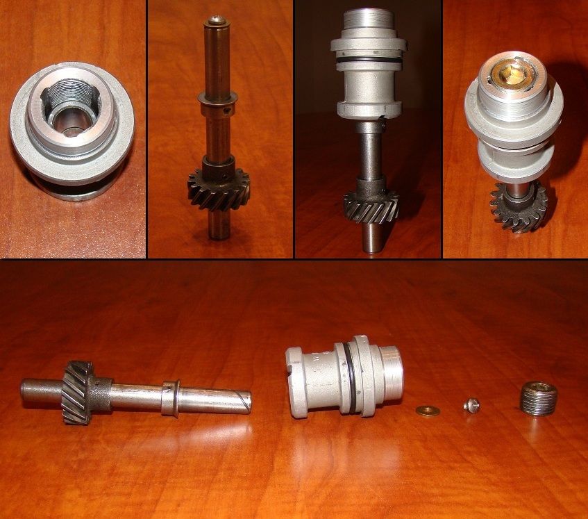
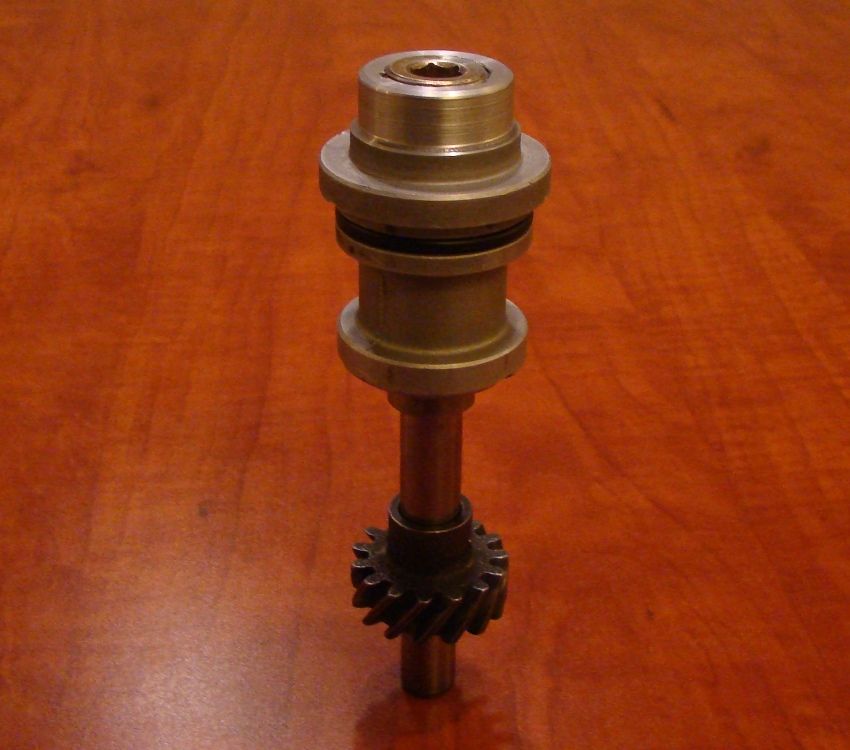
- An “oil pump driver/distributor hole plug” to replace the distributor (available from Price Motorsports Engineering)
- VR sensor (i.e. variable reluctance)
- VR sensor mounting bracket
- An EDIS-8 ignition module
- All associated wiring harnesses:
(A) The cable to connect the VR sensor to the EDIS module,
(B) The cables to connect the coil packs to the EDIS module
(C) The cable to connect the EDIS module to vehicle power
(D) The cable to connect the ignition controller to the EDIS module
(E) A cable to connect the MAP sensor to the ignition controller (not needed if the MAP sensor is integral to the ignition controller) - An ignition controller (such as a Mega Jolt Lite Jr controller) to work in conjunction with the EDIS-8 module replacing the functions of the EEC IV engine management computer. The controller allows the user to adjust the ignition timing parameters. The controller is configured via software using a computer. Among the features of the Mega Jolt Lite controller are an integral MAP sensor (manifold absolute pressure), an external hard rev-limiting circuit and user selection of how much ignition timing advance is utilized during starting. Find the Mega Jolt website at www.autosportlabs.net
- A MAP sensor (i.e. manifold absolute pressure) if it is not integral to the ignition controller
- 2 each Coil packs (each pack contains 2 coils)
- Your preference in a high quality ignition wire kit
- 8 each Boost Engineering EDIS Coil Spark Plug Wire Conversion Kits
- Your preference in spark plugs, gapped to compliment the EDIS ignition
____________________________________________________________
Fabrication
- Fabricate an oil pump driver from an old distributor (or purchase one from Price Motorsports engineering). Keep in mind the oil pump driver gear must be made of a material compatible with the camshaft; an iron gear for iron cam cores and a steel gear for steel cam cores.
- Install the trigger wheel on the crank damper, on the crank pulley, or between the damper and pulley. The mounting position of the VR sensor is dictated by the position of the trigger wheel's missing tooth on the crankshaft. Make sure the trigger wheel is oriented on the crankshaft in such a position to allow mounting the VR sensor in your preferred position on the front of the engine.
- Fabricate a VR sensor bracket. It is a good idea to fabricate or modify the VR sensor bracket so that you have a degree of radial adjustment (closer/farther from the wheel) and angular adjustment (closer/further from TDC). Also, bear in mind that the engine rotates clockwise when viewed from the front.
- Fabricate a bracket for mounting the coil packs on or near the engine.
____________________________________________________________
Installation
Once you decide where to mount everything, and the three or four required parts are fabricated the remainder of the project is a relatively simple bolt-on and plug-in chore. Its a popular upgrade so there's lots of information on the net about performing the installation.
- Remove the distributor and replace it with an "oil pump driver".
- Install the crankshaft damper, trigger wheel and crankshaft pulley.
- Mount the VR sensor bracket and the sensor on the front of the engine.
- Mount the EDIS module and the controller.
- Mount the coil packs.
- Mount the MAP sensor if it is not integral to the ignition controller.
- Connect manifold vacuum to the MAP sensor.
- Wire electric power to the EDIS module and the controller (if needed).
- Install the wiring harnesses and plug the harnesses into the components.
- Install the ignition wires between the coil packs and the spark plugs.
Cylinder pairing for the 351C is cylinders 1 and 6, cylinders 3 and 5, cylinders 7 and 4, cylinders 2 and 8. - Program the controller.
_____________________________________________________________
Mounting and adjusting the VR sensor
The VR sensor and 36-1 crank trigger wheel must be set in the correct relationship to each other. With the engine at TDC for cylinder #1 the VR sensor should be aligned with the fifth tooth beyond the gap created by the missing tooth. This is equivalent to 50° between the missing tooth and the VR sensor at TDC for cylinder number 1. The VR sensor is pointed at the center of the crank wheel, with a 0.030" to 0.060" gap between the VR sensor and crank trigger wheel teeth.
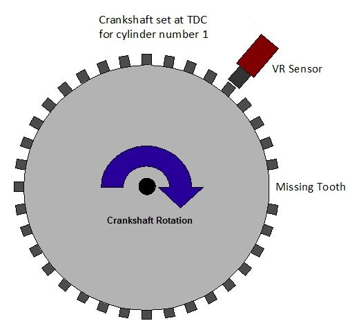
Thus configured the EDIS module should fire the ignition at 10° BTDC, unless the module receives a Spark Angle Word (SAW) command. The 10° advance is constant above 400 RPM. This functions as a limp-home mode; if the EDIS module doesn't receive SAW commands from the ignition controller, it will generate a usable (but not optimal) 10° BTDC of ignition advance.
To test the VR sensor alignment, run the EDIS in the limp home mode. This can be done by disconnecting the SAW/PIP plug, or disconnecting the ignition controller, or removing electric power from the ignition controller. Start your engine and check that the timing is exactly 10° BTDC with a timing light on cylinder #1. If the timing isn't 10° BTDC, adjust the position of the VR sensor until the timing is as close to 10° BTDC as you can get it. Note that at very low rpm (less than 400) the EDIS with no SAW input will start at almost TDC and as rpm increases towards 400 the ignition point will approach 10° BTDC; it will be stable above that engine speed. So the engine must be running to check the timing, timing cannot be checked while cranking the engine with the starter.
_____________________________________________________________
(below) Components of a Ford EDIS-8 Ignition System, a picture is worth a 1000 words

(below) How I fabricated an “oil pump driver/distributor hole plug” utilizing a Ford 351C/351M/400/429/460 distributor.
