click above

The 351C was manufactured in the US for 5 years, in a period of time in which society (supported by US auto manufacturers, yet opposed by the petroleum industry) was seeking to remove lead from gasoline. During the last 3 of those years the 4V version of the 351C was equipped with open chamber heads; these were the Q code engines, the engines we call the "351 Cobra Jet". The majority of the 351C 4V engines manufactured were Cobra Jet versions; the majority of Panteras were equipped with Cobra Jet engines as well. The Cobra Jet engines were equipped with either D1ZE cylinder head castings (1972) having 75.4cc combustion chambers and 8.7:1 static compression or D3ZE cylinder head castings (1973/1974) having 78.4cc combustion chambers and 8.1:1 static compression.

Compression makes a big difference in the way an engine performs, raising the compression ratio is the single most important step to take towards improving the performance of these engines. Raising the compression ratio of any low compression 351C shall increase the engine’s output by about 20 horsepower and improve the engine’s responsiveness. Although this does not sound like a lot of horsepower the amount of snap added to the engine’s performance gives the impression that the horsepower has increased much more than it actually has. The performance most people are looking for from an engine shall only be realized by raising its compression.

To raise the static compression of an engine equipped with open chamber heads usually means (1) replacing the heads with quench chamber heads, (2) installing pop-up dome pistons, or (3) installing flat top pistons (1973/1974), "zero decking" the block, and milling the heads. Most people prefer to install the earlier quench chamber cylinder head castings of 1970 and 1971 (D0AE and D1AE castings). The quench chamber heads are the "easiest" way to raise an engine's static compression; some people also believe the quench chamber heads make more horsepower by virtue of the combustion chamber's shape. In the minds of some people the D1ZE castings are "second class" and the D3ZE castings (equipped with 2V size valves) are "undesirable".

However my personal experience and what I've learned from several folks over the decades has given me a different perspective of the open chamber cylinder head castings, I don't perceive them as second class or undesirable, I don't think owners need to replace them, and in fact they may be throwing away horsepower in doing so. The challenge of raising the compression of an engine equipped with these heads remains however. I would like to propose a fourth method for achieving higher compression, which is to focus on raising the engine's dynamic compression employing a camshaft that closes the intake valve 10° earlier than what is customary.

The purpose of this post is to propose a couple of 351 Cobra Jet engine projects to a dying breed of owners who want to build an engine themselves rather than buying a crate engine or paying someone else to build an engine for them. The projects utilize the OEM block and cylinder head castings. One project utilizes the OEM crankshaft, the other utilizes a crankshaft with a conservative increase in stroke (3.75"). So there's minimal investment in aftermarket parts, however component choices also include forged "round-skirt" racing pistons, a custom ground camshaft, and tappet bore bushings. These choices add about $900 USD to the price of an engine project and have traditionally met with resistance from some owners. My focus is upon building usable street engines that retain factory-like drivability and reliability while releasing the unique potential designed into the factory Cobra Jet (Cleveland 4V) cylinder heads. These are engines appropriate for sports cars like the Pantera, and for street-driven performance cars like Mustangs and Aussie Falcons; they usually attain 100 to 200 more horsepower than their original factory ratings and they operate with vigor over an amazingly wide power band. I don't consider what I do to the engines as "hot-rodding" them but as enabling these amazing engines to achieve the potential built into them. Its tantamount to loosening one's grip on the reigns and giving a race horse its head.


FUEL OCTANE AND COMPRESSION RATIO


The compression ratio of an engine is limited by the octane of the gasoline that shall be used. There are two rating systems for octane being used around the world. Since this is an international forum, it’s important that we are all on the same page. The octane of pump gasoline in Europe, Australia, and most countries of the world is rated using a method named the “Research Octane Number” (or RON). However, the octane of pump gasoline in the US, Canada, and Brazil is rated using the average of the RON rating plus a second rating method called the “Motor Octane Number” (or MON); the formula for the averaged rating is simply (RON + MON) ÷ 2. Fuel rated 95 RON is equivalent to fuel rated 91 using the (RON + MON) ÷ 2 averaged method.

What is not well understood is that 95 octane fuel is the lowest octane fuel available in some European nations, yet the equivalent fuel rated 91 octane in the US and Canada is the HIGHEST octane fuel available in some states; predominantly western states (including California) and Rocky Mountain states. No matter where we are driving in Europe, North America, Australia or New Zealand this 91/95 octane fuel is available to all of us, the car can be driven anywhere or sold to anyone without fuel becoming an issue. For some Europeans it’s the “cheap stuff”, for some folks in the US it’s the “expensive” stuff, and for everyone else it’s a mid-grade fuel. The 1970/1971 versions of the 351C 4V were built to use this fuel off the showroom floor. All of these considerations are factors in my choice to assemble street engines designed for this fuel octane.

An engine’s compression ratio can be understood or defined in three ways:

• By the static compression ratio, which is the total volume above the top piston ring at BDC divided by the total volume above the top piston ring at TDC. This is the most quoted compression ratio, but it is also the least meaningful.

• By the dynamic compression ratio, which is based upon an engine’s effective stroke. The effective stroke begins in the range of 60° to 80° after bottom dead center (ABDC), when the intake valve comes to rest on its seat (is fully closed). This compression ratio is more realistic than static compression, and better for predicting an engine’s anti-knock capabilities. This is the compression ratio engine builders pay attention to. In the "good ol' days" we used to measure this stroke empirically with a camshaft timing wheel and a machinists ruler, today there are "calculators" for doing this, using somewhat complicated mathematic formulas.

• Both the static compression ratio and the dynamic compression ratio "assume" 100% volumetric efficiency (VE). A third method of defining an engine's compression ratio known as the effective compression ratio does not assume 100% VE, it takes into account the density of the air/fuel mixture within the cylinder. Thus effective compression defines a race engine’s compression ratio under wide open throttle conditions, and how it varies with volumetric efficiency and engine speed. This number can be higher or lower than the dynamic compression number, depending upon the intake valve's closing point and the engine's VE at various engine speeds, particularly influenced by "intake charge ram tuning". Street engine's operate 99% of the time at part throttle, therefore this method has no pertinence in building a street engine, I only mention it for the sake of thoroughness ... and to kindle thought.

Although we usually refer to compression ratio in terms of the “static” specification, it’s the “dynamic” compression ratio that more accurately describes the limitation in the amount of compression a motor can tolerate. Based upon the empirical experience of many owners, including myself, the factory Cleveland cylinder heads (iron) can safely tolerate dynamic compression up to 8.0:1, naturally aspirated, carbureted, with full ignition advance, burning 91 octane pump gas (US/Canadian); in fact I know of engines operating just fine at 8.25:1 dynamic compression.

• One method to achieve 8.0:1 dynamic compression ratio is via 11.00:1 static compression with the intake valve closing at 75° ABDC. 11:1 compression is not as big of a deal as some people blow-it-up into being. A cam with 285° intake duration and 113° intake centerline closes the intake valve at 75° ABDC.

• Another route towards achievement of 8.0:1 dynamic compression is via 10.50:1 static compression with the intake valve closing at 70° ABDC. A cam with 280° intake duration and 110° intake centerline closes the intake valve at 70° ABDC.

• A third route towards achievement of 8.0:1 dynamic compression is via 10.04:1 static compression with the intake valve closing at 65° ABDC. A cam with 275° intake duration and 108° intake centerline closes the intake valve at 65° ABDC.

• A fourth route towards achievement of 8.0:1 dynamic compression is via 9.66:1 static compression with the intake valve closing at 60° ABDC. A cam with 270° intake duration and 105° intake centerline closes the intake valve at 60° ABDC.

The point I wish to make from all of this is that an engine having 11.0:1 static compression can operate on the same fuel octane as an engine with 9.66:1 static compression. Conversely an engine having 9.66:1 static compression can make just as much horsepower as an engine having 11.0:1 static compression. In either situation it is merely a matter of camshaft design. The interaction between fuel octane, static compression ratio, and camshaft design must ALWAYS be considered when assembling an engine in order to keep the dynamic compression ratio within the anti-knock capabilities of the engine's cylinder heads.
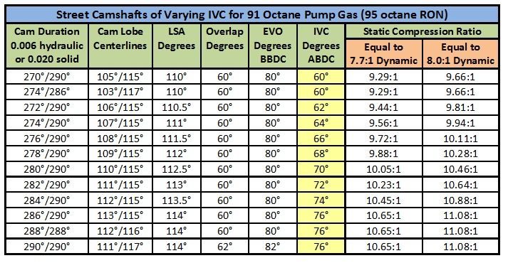

It is my convention to design Cleveland street engines conservatively, for 7.7:1 dynamic compression. By doing so I leave room for variation; variation in assembly, variation in tune, variations in volumetric efficiency, variation in fuel quality, and variation in operating conditions (weather, traffic conditions, engine load, etc). For your comparison, the factory 351 Cleveland engines with the highest static compression ratios, i.e. the 1971 BOSS 351 and the 1970 351 4V, had “nominal” dynamic compression ratios of 7.69:1 and 7.62:1 respectively.
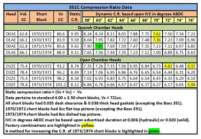

The engine projects I shall propose are designed to operate "comfortably" on 91 octane US/Canadian pump gasoline (same as gasoline rated 95 octane in Europe & Australia). They are designed to achieve 7.7:1 dynamic compression (as per my normal convention) by virtue of balancing when the intake valve closes with the engine's static compression ratio. The dynamic compression ratio is the same whether the engine has 10.0:1 static compression and an intake valve which closes at 70° ABDC, or 9.3:1 static compression and an intake valve which closes at 60° ABDC.


POWER BAND AND HORSEPOWER


The M code version of the 351C 4V was rated for peak horsepower at 5400 rpm whereas the Q code version was rated for peak horsepower at 5800 rpm, which is 400 rpm higher. Both engines utilized cylinder heads with the same size valves and the same size ports, they both utilized camshafts with approximately the same intake duration, they both used intake manifolds of basically the same design, and they both used the same cast iron exhaust manifolds. The engine speed at which peak horsepower occurred rose by 400 rpm by virtue of a camshaft with higher valve lift and a larger carburetor. As we "uncork" the engine further the engine speed at which peak horsepower occurs shall continue to rise, this is the nature of the 4V cylinder heads. The 4V cylinder heads are high port cylinder heads designed in their day to be state-of-the-art NASCAR racing heads, they were significantly tamed for street operation. Peak horsepower of the proposed engines shall occur at approximately 3750 fpm mean piston speed, this is equivalent to 6400 rpm (3.50 stroke) or 6000 rpm (3.75 stroke).

Do not be alarmed by these engines achieving peak horsepower at 6400 rpm! The revised Cobra Jet cams I have designed for this project have no more intake duration than the originals, they are NOT long duration racing cams. We are simply "uncorking" the potential of the engines, allowing them to perform as they were designed to perform. It is not as though they are high rpm engines with no low rpm power, these engines have plenty of low rpm power, peppy throttle response, and good drivability. Factors contributing towards the low rpm performance include good dynamic compression (7.7:1 to 8.0:1), a low-overlap camshaft (60° or less), a dual plane intake manifold, a moderately sized carburetor (750 cfm or less), a carburetor having low speed (part throttle) circuits which are tuned properly, and an ignition calibrated to provide plenty of spark advance at idle (16° to 18°).

The engineers at Ford chose the canted valve cylinder head design for its distinct properties which promote wide flat torque curves. The Cleveland 4V cylinder heads are thus notable for the wide flat torque curves and wide power bands they are capable of creating when assembled accordingly. The 351C with 4V heads is most notable for its tremendous mid-rpm rush of acceleration. However, due to the wide flat torque curve of the Cleveland 4V cylinder head, the power of a 351C simply does not "roll-off" at high rpm like it does with other engines, the engine keeps pulling and pulling, it revs its heart out for you if you ask it to. The engine's ability to accelerate and to rev at high rpm is either frightening, awe inspiring, or intoxicating ... depending upon your personal perspective.
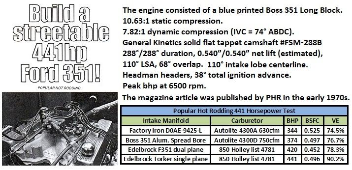

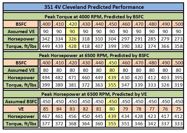
The “typical” engine from which I have extrapolated the data below was equipped with 4V quench chamber heads, flat top pistons, 8.0:1 dynamic compression, 36°/38° total ignition advance, a hydraulic camshaft (typical specs: 275°/285° duration at 0.006, 0.550/0.560 net valve lift, 52° overlap), stiff push rods, and recommended valve springs (Crane, Manley or PAC Racing). Engines with hydraulic roller cams used Crane or Morel tappets, never OEM Ford tappets. Induction and exhaust included a dual plane intake manifold (usually Blue Thunder) with exhaust heat in service, 750 cfm carburetor, and headers with 2” OD primaries (amongst Panteras the Hall GTS headers were predominant). The engines possessed good drivability, and strong mid-range acceleration that doesn't roll-off at high rpm, it just keeps pulling and pulling.


ENGINE DEMAND, CAMSHAFT TIMING and CYLINDER HEAD FLOW


An engine's demand for gas flow is based upon piston motion. A piston begins descending on the intake stroke at about 30° ATDC, it reaches the maximum velocity of its descent at about 70° ATDC, it begins decelerating at about 110° ATDC, and comes almost to a stop at 150° ATDC (30° BBDC). Therefore an engine's demand for gas flow begins accelerating at 30° ATDC and its highest demand for gas flow occurs between 70° and 110°ATDC. There are two criteria therefore that impact our ability to design an induction system to complement these demands:
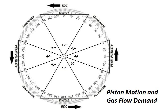

• An intake lobe centerline of 90° ATDC (half way between 70° and 110°) would be ideal, however such camshaft timing for a street engine would require an intake lobe of only 240° duration. I don't think conventional minds are ready to accept a camshaft having 240° intake duration and an intake centerline of 90°. The small selection of camshaft lobes having 240° duration, none offering very high lift, is another drawback. So for now it is best to time an intake lobe centerline for a street engine's camshaft as early as acceptable, and to use lobes of longer duration in which there is a wider selection of choices. An intake lobe centerline varying from 103° to 113° is acceptable, but such camshaft timing shall be out of sync with piston motion by 13° to 23°!

• Since camshaft timing is not synchronized perfectly with piston motion the more air flow the cylinder head can provide throughout the entire range of valve opening is important, NEVER just the peak number. After 60° of duration the valve must be lifted open high enough, and the cylinder head must flow sufficiently, to meet the needs of the accelerating piston. Mid-lift flow after 100° of duration capable of meeting an engine's peak demand is significantly important. If a cylinder is filled with air/fuel almost 100% (or more) by 30° ABDC there is little to be gained by ram tuning.


ARE THE OPEN COMBUSTION CHAMBER 4V CYLINDER HEADS REALLY SECOND CLASS?


Quench

The flow coefficient of a shrouded valve is worse than the flow coefficient of an unshrouded valve. Valve shrouding is a big issue in cylinder head design. Cleveland valves unshroud themselves as they open by virtue of the canted valve geometry, but the low lift flow coefficients of all "quench chamber" Cleveland cylinder heads are significantly impacted by shrouding. The issue of shrouding is one of the reasons why the modern “Yates high swirl” combustion chambers are superior to earlier quench designs; the high swirl chambers do a better job of unshrouding the valves while promoting a "specific" type of turbulence within the combustion chamber known as swirl (diffusion of the air/fuel mixture and funneling of the exhaust gas are also promoted).
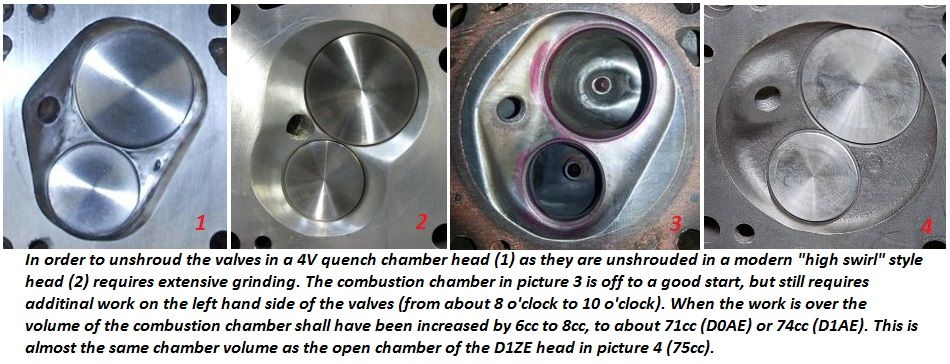

There is a belief system within hot rodding that "quench" makes power. While this is true for some cylinder heads it is not true for all. Some cylinder heads shield a significant portion of the fuel/air mixture within the cylinder from the flame front. Of course unburned fuel does not contribute to making power. The idea behind "narrow quench space" in those heads is to squeeze as much air/fuel mixture as possible out of the quench space and into the actual combustion chamber where it is no longer shielded from the flame front, where it shall be ignited and thus contribute to making power. Combustion chambers with lots of quench are an inherently faulty design, and the convention of narrowing the piston clearance in the quench area is a "means" for extracting more horsepower from engines equipped with such cylinder heads. We are of course talking about the wedge chambers of small block Chevys and small block Fords.
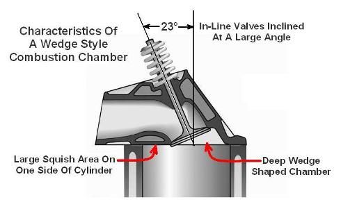

The broad and shallow Cleveland chambers, resulting from the low valve angles, are superior to wedge chambers. Open chamber versions of the Cleveland head obviously have no quench areas to shield any portion of the combustion chamber from the flame front. There isn't enough quench area to make a detrimental impact upon horsepower in the quench chamber versions of the Cleveland cylinder head either; no part of the combustion area is significantly hidden from the flame front, minimizing quench clearance is not needed to expose otherwise unburned air/fuel mixture. The Cleveland cylinder head creates turbulence within the combustion chamber by virtue of the chamber's shallowness. I know from experience the open chamber heads resist detonation equally as well as the quench chamber heads, both versions can operate at the same compression ratios.

So how does the performance of quench chamber and open chamber heads differ?

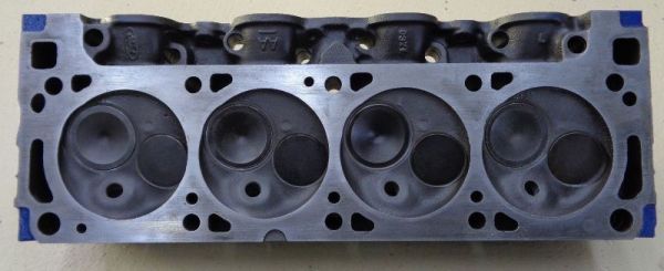
The small amount of quench surrounding the combustion chambers of the Cleveland quench heads is intended to squeeze the fuel and air mixture around the periphery of the cylinder towards the middle thus improving low rpm power (faster combustion at low rpm), but Ford engineering stated that design didn’t contribute significantly to mid or high rpm power. Unfortunately the chamber design of those heads shrouds the valves extensively, especially at low valve lift. Open chambers corrected this problem, which is a far more important aspect; they improved the cylinder head’s low lift flow coefficient via unshrouding the valves. The low lift air flow of the intake port of an open chamber 4V cylinder head exceeds the low lift air flow of the intake port of a quench chamber 4V cylinder head by at least 25 cfm from 0.100" valve lift to 0.300" valve lift.

The D1ZE open chamber cylinder head went into production about May 1971. Ford engineering promoted the D1ZE cylinder head for racing in the Off Highway Parts manual of 1972. They claimed the heads flowed better, but they also advised using the D1ZE heads would require the development of custom pop-up dome pistons to raise compression. Ford engineering was no longer as closely involved with the race teams as it had been, because Ford pulled financial support from the entirety of their racing operation at the end of the 1970 season. The Off Highway Parts operation was shut-down too, in February 1973. Development of the open chamber heads for racing fell by the way-side.

I have known people racing the 351C in competition who have preferred the open chamber D3ZE cylinder heads as far back as the 1980s. Each of them had developed their own custom pop-up dome piston to build compression. They could have used any factory cylinder head they chose, and they were adamant that their race car was fastest using the D3ZE cylinder heads.

Valve Sizing

While big valves offer improvements in performance, there is such a thing as too big, the issue is again related to the subject of valve shrouding. The optimum balance between valve size and valve shrouding is considered today to be about 53% of the bore. Big valves are beneficial, because for a given amount of lift a bigger valve opens more curtain area ... so the big valve exposes more curtain area faster. But if the valve is so big that shrouding becomes an issue then that curtain area will not be realized. You're fooling yourself if you think a big valve is always better, even when its shrouded. BUT (that's a big but) a valve is only capable of allowing a certain throat diameter. And a certain throat diameter is only capable of supporting a certain bore and stroke up to a certain rpm (I calculate maximum throat as valve diameter minus 0.3"). So the first question is how much throat does your engine need to avoid sonic choke?

The Cleveland cylinder heads were first produced with 2.23 intake valves (1969 Boss 302). The intake valves were downsized to 2.19 in 1970, that valve was still too big for a 4.00 bore, but they were planning to use 4.080 bores in NASCAR (the Chevy 396 also had a 2.19 intake valve, its bore was 4.094). The intake and exhaust valves of the production head (street engines) were downsized again in 1973; some will disagree, but I believe the engineers at Ford were still learning and each change was intended to improve the engine.

Those last 4V cylinder heads, the D3ZE castings, down-sized the valves to the size of 2V valves (2.05 intake valves and 1.65 exhaust valves); these 4V castings had combustion chambers which were for the first time a perfect 4 inch diameter circle, and the 2V sized valves actually fit within that 4" diameter combustion chamber ... the result was of course less shrouding and therefore improved air flow. The D3ZE cylinder heads were in fact the first and only factory 4V heads truly designed for a 4.00 inch bore. A 2.05 valve should be capable of being ported to 1.75 throat. This will supply a 357 at 7300 rpm.

Remembering the 53% rule, the 2.05 inch diameter 2V intake valve of the D3ZE cylinder head could have been upgraded to a 2.12 valve, which is certainly a "big valve" for a 4" bore but one that is not "over-sized". A 2.12 valve (1.82 throat) will supply a 357 at 7900 rpm. This valve is all you're gonna stuff into a 4" bore without getting into shrouding. So here's the point where we achieve the best curtain area and largest throat; anything larger is a compromise between throat diameter and curtain area. If we select a larger valve it should be because we need the increased throat size, and are willing to sacrifice air flow to achieve a higher sonic choke point. However, even with a bigger intake valve the D3ZE heads would have still had one down side; like the D1ZE heads, their 78.4cc combustion chamber volume made it difficult to build compression with flat top pistons.

NASCAR lowered the displacement limit to 358 cubic inches as of the 1974 season (4.030 bores). In spite of the reduction in bore diameter the NASCAR teams continued to use 2.19 intake valves (capable of being ported to 1.9 throat) which supplied a 358 up to 8500 rpm. The NASCAR teams needed this rpm capacity, but there was a price to pay for stuffing that much throat capacity into a 4" bore.

Port Height

At this point some people may ask, if open combustion chambers and smaller valves are better, why not use US 351 2V heads or Australian 351C heads?

Canted valve cylinder heads have several advantages, among them is (1) the ability to use larger valves than what is possible with a “wedge” head, (2) smaller valve angles promote higher thermal efficiency via a broad and shallow combustion chamber, (3) the push rods are angled apart eliminating the pinch point where the intake port passes between them, and (4) the valves “unshroud” themselves as they open. There is however one drawback to cylinder heads having “small” valve angles, for a given port height the angle at which the intake port intersects the valve pocket is less favorable. Therefore canted valve cylinder heads with small valve angles NEED higher ports to achieve an interface angle between port and valve pocket equivalent to the interface angle of a wedge head, and thus to realize the air flow performance they are capable of achieving. The Cleveland 2V intake port is the same height as the intake port of a small block Ford wedge cylinder head, and thus at a disadvantage in this aspect. The "low port" (i.e. 2V) Cleveland cylinder heads are decent heads, many people are quite satisfied with their performance, but they do not have the air flow capabilities of the high port (i.e. 4V) Cleveland cylinder heads. The Cleveland 4V intake port is a 1/2 inch higher and the ramp cast into the entrance of the 4V intake port enables it to behave as an even higher port; port height is precisely why the 4V heads flow better than the 2V heads.

Port Size

You may next ask isn’t the 4V intake port too large?

The 4V intake port is physically large at the inlet, but it becomes quite a bit smaller further inside. In spite of the large inlet the port's average cross-section is only 2.9 square inches, and its volume is 242cc. It is tuned for about 6400 rpm (3750 FPM mean piston speed). If you compare the average cross-sectional area of the 4V intake port to the average cross-sectional area of the intake ports of several popular aftermarket SBF or SBC cylinder heads, tuned for about 6000 rpm, you shall find that rumors of its “largeness” are exaggerated. If you want to argue that 6400 rpm is too high for a street engine, that is of course a valid argument ... but only in a world conditioned to thinking that anything more than 6000 rpm is too much. That was not the prevalent perception in 1970. In the case of the 351 Cleveland peak horsepower can be attained at that rpm while maintaining good low rpm performance, and without great expense. The Cleveland Ford's wide power band and willingness to rev is an intoxicating discovery for many owners.

The 4V cylinder head was designed to make the intake valve size the limit to gas flow, the intake ports were logically designed to support the capabilities of the intake valve. The maximum throat diameter of a 2.19 intake valve is 1.9 inches; sonic choke at that throat diameter occurs at an average piston speed of 5000 fpm; equivalent to 8600 rpm in an engine having a 3.50” stroke. It has been long held that the maximum average piston speed for an endurance racing engine is about 5000 FPM; the coincidence between these two parameters was not accidental.

The 4V port gas velocities are indeed on the low side of modern standards, but not tremendously so. Ford was paying close attention to gas velocities within the ports by the time the Cleveland cylinder heads were being developed. Careful attention was paid to avoid sonic choke at peak piston acceleration. Piston speed is the source of gas velocity; whenever the cross-sectional area of an intake port is reduced to "artificially" increase gas velocity beyond that which is the result of piston speed, that intake port becomes a restriction to gas flow at high rpm. The 4V intake port was sized to be big enough to avoid becoming a high rpm restriction to gas flow, but it was also sized to avoid reducing gas velocity more so than what is necessary. Thus in spite of its high rpm capabilities the 4V intake port remained viable as the intake port for a 351 cubic inch street engine. This is what was meant when back in 1970 Ford engineers described the ports of the 4V cylinder heads as having been “carefully” sized. “Ram tuning” however was not the “hot topic” in 1970 as it became in the 1990s. The port gas velocity goals in that era were simply not as vigorous as they are today; the 4V Cleveland intake port was however designed to operate on the “high side” of those older standards. It is my understanding that race engine designers target about 325 fps in a modern port, whereas the Cleveland port “cleaned-up” for racing operated at about 305 fps. In order to operate at today’s higher gas velocities a modern race port must be straighter, have constant cross section and shape, and have a very large short-side radius (it must be a higher port).

One of the challenges in induction system design is enabling the air/fuel mixture to transition from the intake port to the intake valve pocket in a manner that does not impede flow. As gas velocity within the intake port increases it becomes more difficult for the fuel/air mixture to negotiate the short turn radius from the intake port into the intake valve pocket. There are three methods in which ports are tailored to accomplish this. The first is to raise the port in order to make the short turn radius larger; the second method is to increase the size of the valve pocket and the size of the port at the valve pocket entrance in order to reduce gas velocity as it negotiates the short turn radius, the third method is to adjust the average cross-section of the port and therefore adjust the average port velocity. These parameters are interactive, and they are influenced by factors such as engine height limitations, engine output expectations, and the engine's power band. It is my experience that the Cleveland 4V intake port is a good compromise of air flow, port height, and engine power band; any cylinder head claiming to have equal or better gas flow AND higher gas velocity has a higher port entrance, or a dropped combustion chamber, or both.
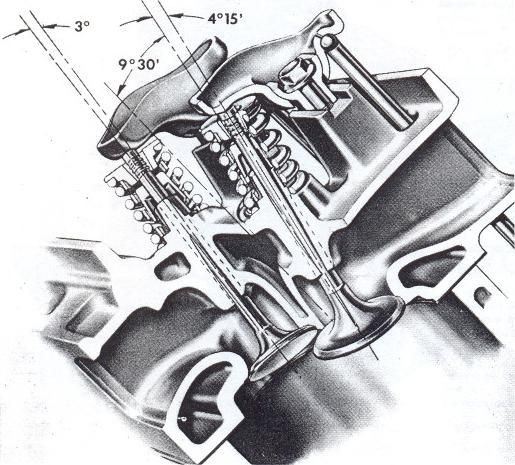

The inlet of the 4V intake port is large because there is a ramp built into the floor of the port. The port floor was lowered about 1/2" to accommodate the ramp, adding about 15cc to the port's volume in the process. The ramp was put there to improve air flow in lieu of raising the port any further. NASCAR had rules back when the Cleveland was designed that prevented using cylinder heads that resulted in engines too tall for production automobiles. This is the same ramp design that was employed in the medium rise FE cylinder heads, after NASCAR had outlawed the high rise FE cylinder heads. The ramp actually works, it does indeed increase airflow, unfortunately it also results in a port having an irregular shape. The irregular shape does not seem to hinder performance at engine speeds below 7000 rpm however. Of course I would prefer a 1/4 inch higher intake port without all the tricks of the 4V intake port, one that is consistent in shape and cross-section, and about 7% smaller in average cross sectional area; that more or less describes the intake port of the Ford Motorsport M-6049-B351 cylinder head of 1985. But in the absence of that option amongst the factory iron heads I prefer the 4V intake port with its tricks over the lower 2V port.

I have found 4 common themes amongst owners who are unhappy with the lower rpm performance of the 4V head equipped Cleveland engines in their car: (1) insufficient compression, (2) too much cam, (3) a poorly operating or poorly calibrated carburetor, or (4) not enough gear. It is not commonly understood in the hot rod community that engines with large canted valve cylinder heads cannot tolerate as much overlap as other engines if low rpm performance and drivability are desired. When it comes to the 351 Cleveland everyone’s first reaction is to blame the intake port for being too large.

Summary

The engineering that culminated in the 4V Cleveland cylinder head was the result of extensive research, testing, and the experience of professional engineers and championship winning racing teams. The 4V Cleveland cylinder head was a landmark development, its engineering continues to be the foundation of OHV racing cylinder heads to this day.

There are no bad production Cleveland heads, they all have their merits. They all share the same excellent "shallow poly-angle" combustion chamber design and canted-valve geometry. The 2V (low port) heads are tuned for lower rpm, they can be fitted with 2.12 intake valves (as advised for the D3ZE heads), and their open combustion chambers have the advantages of improved low-lift air flow. Although their air flow flattens out at 0.500" lift due to their "low port" design, they are still capable of supporting over 400 horsepower. The D0AE and D1AE quench chamber 4V heads offer excellent air flow capabilities due to their big valves and high ports, their reduced chamber volumes make it easier to achieve 10:1 static compression with a standard displacement engine, and the small amount of quench provides good low rpm torque. The D1ZE open chamber 4V head castings have the same big valves and high ports, but they trade the low rpm torque of the quench chamber heads for improved low-lift air flow at ALL rpm. The D3ZE castings have the same port height as all 4V heads, they have the open chambers which promote better low-lift air flow, and they have chambers and valves sized properly for a 4" bore thus un-shrouding the valves even better than the D1ZE heads. The 4V heads which some people consider "undesirable" are possibly the best factory "iron" Cleveland head produced for the standard 4.00 bores of the production engine. They are not perfect by any means, but they are in most ways the best choice amongst all the factory castings from the US or Australia ... their one drawback being the 78.4cc volume of the combustion chambers. Milled the maximum amount (0.060") their chamber volumes can be reduced to 66cc (same as the D1AE quench chamber heads), but I'll explain a better way to resolve this issue below.


THE REVISED COBRA JET CAMSHAFT


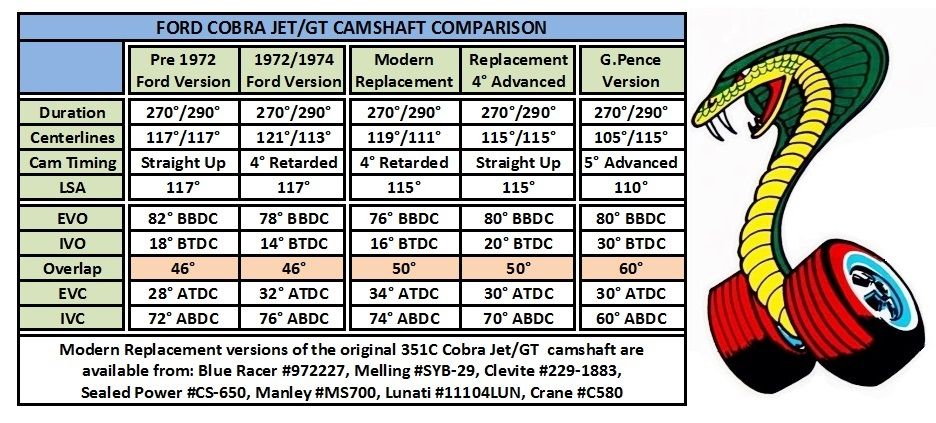
The original Cobra Jet camshaft combined a race cam exhaust lobe for good high rpm performance along with a short duration intake lobe for good drivability, the specs were 270°/290°. The camshaft had low overlap (46°) which also contributed to good low rpm power and drivability. It opened the valves quite a bit for a street cam designed in 1966 (the original application was the 390 GT), the lift specs were 0.481/0.490.

I've revised the Cobra Jet camshaft lobe centerlines, setting them at 105°/115°. This has the effect of narrowing the lobe centerline separation angles to 110°, and timing the camshafts 5° advanced. That's fairly standard camshaft timing for this day and age. Be assured I haven't done anything strange or wonky. Thus reconfigured the intake valve closes at 60° ABDC, which is 10° to 16° earlier depending upon which camshaft timing you are comparing it to. The purpose behind this change is to build good dynamic compression with lower static compression. Narrowing the lobe centerline separation angle increased overlap, which is now 60°. This is very close to the same overlap as the original Boss 351; its not excessive but you wouldn't want any more than that for a street engine. The overlap period is now centered very well around top dead center, and it is within the dwell period at TDC. This serves to minimize the effect overlap has upon the engine's low rpm performance and drivability. The exhaust valve opens early enough to encourage high rpm performance even with a quietly muffled exhaust system. The intake valve begins opening 10° to 16° earlier and reaches full open 10° to 16° earlier, this makes more horsepower. Thus the revised Cobra Jet camshaft has all the benefits of an aftermarket narrow LSA camshaft without any of the typical drawbacks.

Unfortunately camshafts ground to this specification are not available off-the-shelf, they shall have to be custom ordered. I shall provide specifications for moderate lift hydraulic cams, high lift hydraulic cams, and high lift solid tappet cams, for either flat tappets or roller tappets (something for everyone) in another section below. When combining these cams with the factory iron heads I recommend keeping the static compression ratio within the range of 9.05:1 to 9.65:1, with a recommended target of 9.3:1 static compression or 7.7:1 dynamic compression.

The Cobra Jet engines, equipped with open chamber 4V heads and my revised version of the Cobra Jet camshaft, shall achieve higher output than engines equipped with quench chamber 4V heads due to (1) improved air flow at low valve lift as a result of unshrouding the valves and (2) due to opening the intake valve significantly earlier due to moving the intake lobe centerline to 105° ATDC.


Continued Below
.
Last edited {1}
Original Post

Replies sorted oldest to newest


CONSTRUCTION CONSIDERATIONS - RESOLVING WEAKNESSES and IMPROVING DURABILITY


All Engine Projects

The 351C has 5 weaknesses that should be considered for all engine projects, even a simple rebuild. It is negligent and unwise to "rebuild" a 351C and not address these issues in the process, especially if the intention is to "uncork" the intrinsic performance of the engine as we are planning. These issues should guide a mechanic's decisions regarding what work to perform and which parts to purchase. And that's why I choose this topic as a starting place to embark upon a Cleveland engine project.

(1) The OEM Valves

• They were designed with a multi-groove spring keeper which Ford claimed is not suitable for high rpm.
• They are brittle, they develop cracks, and the heads fall off the stems from time to time, even at low rpm.
The "Fix" is to replace the OEM valves with top quality single groove valves.


(2) The OEM Crankshaft Damper

• It is old, the rubber does not have the compliance it did when it was new, it does not perform as it was designed to perform.
• It is unbonded, if the ring hasn't already begun to move it shall eventually.
• It is made from iron, not the good SG (nodular) iron, just standard cast iron.
• It is too light for operation over 6000 rpm.
The "Fix" is to replace the OEM damper with a new, heavier, fully bonded, all steel damper.

(3) The OEM Breaker Point Ignition

• The breaker points require periodic adjustment.
• The breaker points bounce above 6000 rpm.
• The ignition's output diminishes above 5000 rpm.
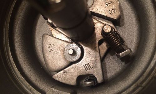
• The performance of the advance mechanism becomes erratic with age and/or mileage.
The "Fix" is to replace the OEM distributor with a new or rebuilt breaker-less distributor.

(4) The OEM Connecting Rod Nuts

• They strip their threads at high rpm.
The "Fix" is to replace the OEM connecting rod nuts with top quality ARP nuts.

(5) The Lubrication System
The 351C lubrication system is notoriously problematic. Ford's hot oil pressure specification was 60 psi (+/- 10 psi) by 2000 rpm.

• The large "ports" connecting the tappet bores to the lubrication passages allow an excessive amount of oil to be wasted via the tappet clearances.
• The large "ports" connecting the tappet bores to the lubrication passages allows cavitation created by tappet motion to impede the amount of oil flowing to the main bearings.
• Impeding the amount of oil flowing to the main bearings results in providing insufficient lubrication to the rod bearings, and causes rod bearing wear and damage.
• Oil wasted via the tappet clearances and via the clearances caused by worn rod bearings over taxes the oil pump’s capacity making it impossible to achieve Ford's hot oil pressure spec.
• Oil pressure "sags" at high rpm for the same reasons.
• Oil not only lubricates bearings, it cools them as well. At some point above 7000 rpm the rod bearings fail completely due to under-lubrication. If complete failure occurs at 7000 rpm, then impending failure is occuring at 5000 rpm, and the precursors to failure are occurring at 3000 rpm.
• The large "ports" connecting the tappet bores to the lubrication passages create tappet compatibility issues, and often supply too much oil to the valve train. Under these conditions the oil pan can be "pumped dry" at constant high engine speeds.
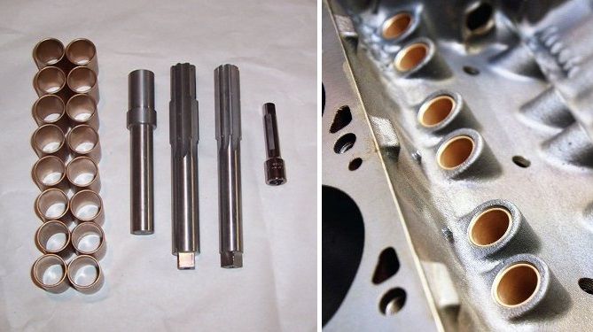
The "Fix" is to minimize the size of the ports connecting the oil passages to the tappet bores, via the installation of bushings with 1/16" orifices.


Extended Performance Projects

These issues should be considered for projects beyond a basic rebuild.

(1) The Cylinder Walls of the Production Block

• They are thin and they have a reputation for cracking under demanding use.
The "Fix" is to install pistons with a "fully round" skirt design which spreads piston thrust forces over a wider area of the cylinder wall.

(2) The OEM Oil Pan

• The lubrication system cannot lubricate the engine unless a constant supply of non-aerated oil is delivered to the oil pump suction every moment the engine is in operation.
• The OEM oil pan is not designed for high G-Force maneuvers (braking, acceleration, cornering).
• Modern sports cars with the performance capabilities of the Pantera are equipped with dry sump lubrication systems.
• Unless you only plan to "cruise" in your Pantera, then you must consider installation of a wet sump style road race oil pan.
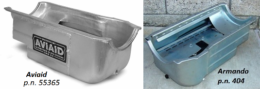
The "Fix" is to replace the OEM oil pan with a high capacity road race oil pan, with baffles, scraper, and windage tray.


(3) The OEM Push Rods

• They flex at high rpm, even with the moderate force of the OEM valve springs.
The "Fix" is to replace the OEM push rods with push rods made of larger diameter, heavier wall, seamless chromoly tubing.


(4) The OEM Valve Springs

• The valve springs are intentionally designed to allow valve float above 6000 rpm.
• The valve springs are not compatible with modern "high lift" camshaft lobes (over 0.500").
The "Fix" is to replace the OEM valve springs with valve springs designed to provide higher force and to accommodate higher valve lift.

(5) The Balance of the Reciprocating Assembly

• The reciprocating assembly was "only" statically balanced by Ford.
• Vibration and harshness increase with engine speed.
• Increased vibration is destructive to the engine.
• Increased harshness makes it unpleasant to operate the engine at high rpm.
• Replacement of pistons or connecting rods will require rebalancing the reciprocating assembly anyway.
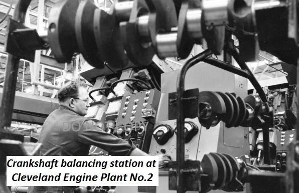
The "Fix" is to dynamically balance the reciprocating assembly.

Dynamically balancing the reciprocating assembly not only improves the durability of the engine, it makes the engine more inviting to operate at higher rpm. It imparts a feeling of smoothness to the engine, a quality normally only found in high end, expensive automobiles.


Pantera Problems Impacting the Engine

There are two additional "issues" unique to the Pantera which impact the engine's operation.

(1) The Fuel Tank Outlet Tubing

• The metal tubing in the Pantera's fuel tank that supplies the fuel pump is only 5/16" OD; this is much too small.
The "Fix" is to upgrade the size of the tubing to 1/2".

(2) The Engine’s Coolant System
The Pantera's coolant system is notorious for overheating at low speeds. There are 3 contributing factors.

• Air in the coolant system collects in the radiator, the cooling system has no functional air removal system.
• Coolant bypassed the radiator due to leakage around the OEM radiator’s vertical baffle (revised April 1973, approximately chassis no.5200).
• The coolant flow rate is insufficient, resulting from the length, diameter, and number of bends in the coolant system plumbing.
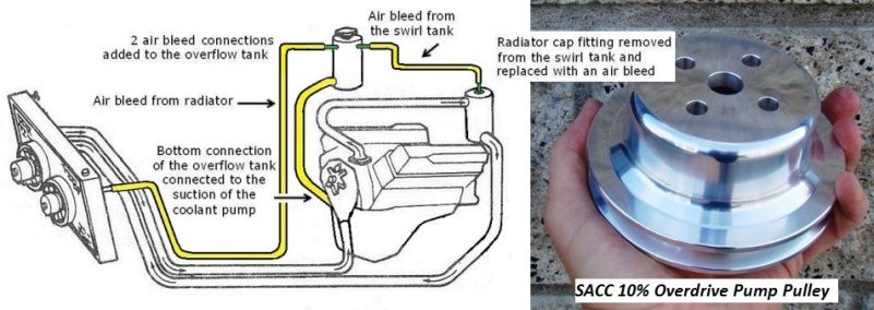
The "Fixes" are to implement methods to positively remove air from the cooling system (manually or automatically) and to increase the coolant flow rate. Go here for more information: Engine Forum, Sticky #2


CONSTRUCTION CONSIDERATIONS PART 2 - UNCORKING and ENHANCING HORSEPOWER


Resolving engine reliability issues and improving durability were the aspects involved in the recommendations above. Additional criteria involves "uncorking" the potential of the engine and enhancing horsepower. None of these methods for enhancing horsepower involve building a rough idling or temperamental race engine.

Primary Method- Optimizing Thermal Efficiency (improves BSFC)

• How well the piston rings seat and seal within their bores is the most influential aspect of an engine in term of making horsepower. You want to have the bore honed appropriately for the rings you have chosen and the oil you plan to use. The main bearing caps and head "torque plates" should be torqued to spec during the honing procedure. The rings should be hand fitted to the bores. Then they must be broken-in appropriately. Seek guidance from your piston ring manufacturer.
• Raise dynamic compression to between 7.7:1 and 8.0:1. This is a very important step towards achieving satisfying "seat of the pants" performance.
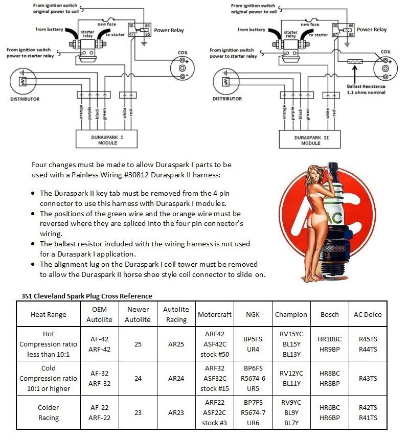
• Utilize a high output, dynamic dwell ignition; and have the ignition properly tuned.
• Utilize a carburetor with annular booster venturis; and have that carburetor properly tuned.

Minimizing Friction (improves BSFC)

• Piston ring drag on the cylinder walls is a major source of power-robbing friction. Modern thin piston rings are not only designed to seal better, they are also designed to reduce friction, via lower tension and reduced contact patch. The Ross pistons I've recommended below are designed for modern "thin" piston rings.
• The operating friction of engines utilizing the 3.5 stroke OEM crankshaft can be reduced by utilizing longer (351W length) connecting rods.

Uncorking the Engine's Intrinsic Volumetric Efficiency (improves VE)

• Improve low-lift flow by utilizing open chamber 4V heads, with a preference for the smaller valve D3ZE castings.
• Improve cylinder head performance, especially at low valve lift, via pocket porting, combustion chamber blending, and 3 angle valve profiling.
• Utilize high flow "racing style" intake valves.
• Utilize a camshaft which opens the intake valve earlier, having an intake centerline of 105° ATDC.
• Utilize a high lift but low overlap camshaft.
• Optimize rocker arm geometry.
• Select the 3.75 stroke crankshaft for a 7% increase in piston speed and 4.5% increase in gas velocity.
• Weld closed the exhaust heat cross-over of intake manifolds thus equipped.
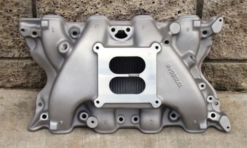
• Utilize an intake manifold that performs better than the factory intake manifold.
• Utilize a carburetor of appropriate size for your intended VE.
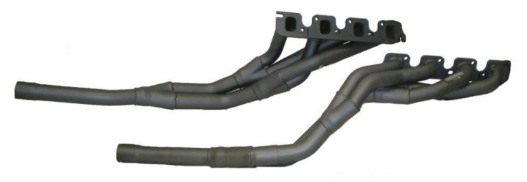
• Utilize tubular exhaust "headers" of tri-Y or 4 into 1 design, and larger diameter tail pipes.

Note: The Advantages of Ross Pistons

• They are forged aluminum and very durable, they will tolerate cylinder imperfections, horsepower, and engine speeds that other types of pistons cannot.
• Their round skirt design improves cylinder wall durability.
• They are drilled for wrist pin oiling out-of-the-box.
• They are designed to utilize modern "thin" piston rings which reduce piston ring drag (less friction).
• Modern "thin" piston rings also seal better (improved thermal efficiency).
• They are available from Summit Racing at a FAIR price, including custom orders.
• Although there are pistons available for less money, none of them offer all of these advantages.


ENGINE #1 - THE PRODUCTION 351 COBRA JET

(351 or 357 cubic inches)


Reciprocating Assembly:
• Stock nodular iron 3.50 stroke crankshaft, 2.31 diameter x 1.66 wide rod journals, external balanced.
• Stock 5.78" heat treated 1041 steel I-beam connecting rods, stock 3/8 150,000 psi fasteners (1.65:1 rod length to stroke ratio).
• Replacement nuts for the connecting rods, ARP p.n. 300-8371.
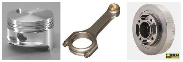
• Ross round skirt flat top pistons 80556, 1.668 pin height, std. 0.912 wrist pin.
• Power Bond "Race Performance" damper PB1082SS, steel hub and steel ring, SFI approved, Fully Bonded, 28 oz. imbalance (made in Australia).
• Yella Terra steel flywheel (for long-style clutches) YT9902, 26.4 pounds, 28 oz. imbalance.
• Dynamic balancing.
• Cleveite tri-metal bearings, MS1010 mains, CB927 rods.
• Bearing clearances: 0.0025 – 0.0030 Mains; 0.0023 – 0.0028 Rods.

Notes:
• An upgrade from the factory connecting rod is the Eagle chromoly H-beam connecting rod, p.n. CRS5780F3D. It has a doweled big end, it uses 7/16 chromoly cap screws, and it is bushed for floating wrist pins. It is designed to use 351W bearings p.n. CB831. The rod bolts are torqued to 63 ft/lbs. It is rated for up to 750 horsepower. It is recommended when a solid tappet camshaft is chosen.
• An upgrade from the Power Bond crankshaft damper is a damper manufactured by BHJ Dynamics, p.n. FO-EB351C-7. It has a steel hub and steel ring, it is SFI approved, it is Fully Bonded, it weighs 10 pounds, and it is designed for 28 oz. imbalance. It is a top shelf damper. If you are planning on a solid tappet cam, and Eagle connecting rods, this damper shall compliment your choices (it costs about 3 times the price of the Power Bond damper).
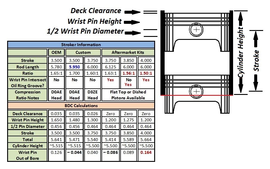
• Another possible connecting rod and piston combination involves the 351W chromoly H-beam connecting rod manufactured by Eagle, p.n. CRS5956F3D. Like the 351C connecting rod it has a doweled big end, it uses 7/16 chromoly cap screws, and it is bushed for floating wrist pins. It is also designed to use 351W bearings p.n. CB831. The difference is its length, it is 5.956 inches long. Combine this with a custom ordered Ross piston having a 1.492 pin height (0.912 wrist pin diameter). With this combination the wrist pin is not pulled out of the bore at BDC as it is with the OEM combination, plus the rod length to stroke ratio is increased to 1.7:1, same as the 351W. This is considered the upper end of the optimum range, meaning this rod length to stroke ratio provides the least amount of cylinder wall thrust without impacting acceleration. A longer rod would decrease thrust even more, but it would also have a negative impact on acceleration. These two changes will lower the engine's operating friction, decrease frictional power losses, and increase horsepower.


Camshaft Timing Set:
Rollmaster CS3091, Ford Racing Performance Parts M-6268-A351, or Cloyes 9-3621X9.

Cylinder Head Option No.1: 1972 (D1ZE Castings)
• D1ZE open chamber 4V heads, 75.4cc chambers.
• If the intake valve throats remain at 1.75 diameter (this is the stock – unported dimension), sonic choke shall occur at 7300 rpm.
• Install Manley valves.
• Utilize head gaskets having 0.040 or 0.048 compressed thickness.
• The static compression ratio goal is 9.30:1.

Notes:
• 0.048 head gasket is for 4.030 bore & 9.200 deck, 0.002 deck clearance. Mill the heads 0.0025 (74.9cc).
• 0.040 head gasket is for 4.000 bore & 9.215 deck, 0.017 deck clearance. Mill the heads 0.016 (72.2cc).
• Intake valve, Manley Race Master, 2.19 diameter valve head, 5.24 length, 0.3415 stem diameter (11/32).
• Exhaust valve, Manley Severe Duty, 1.71 diameter valve head, 5.05 length, 0.3415 stem diameter (11/32).

Cylinder Head Option No.2: 1973/1974 (D3ZE Castings)
• D3ZE open chamber 4V heads, 78.4cc chambers.
• Upgrade the heads with 2.125 intake valves.
• Open the intake valve throats to 1.65 diameter minimum; at that dimension sonic choke shall occur at 6500 rpm.
• Install Manley valves.
• Utilize head gaskets having 0.040 compressed thickness.
• The static compression ratio goal is 9.30:1.

Notes:
• An intake valve throat diameter of 1.71 will raise sonic choke to 7000 rpm.
• For 4.030 bore & 9.200 deck, 0.002 deck clearance. Mill the heads 0.0095 (76.5cc).
• For 4.000 bore & 9.215 deck, 0.017 deck clearance. Mill the heads 0.031 (72.2cc).
• Intake valve, Manley Race Master or Race Flow, 2.125 diameter valve head, 5.24 length, 0.3415 stem diameter (11/32).
• Exhaust valve, Manley Severe Duty, 1.65 diameter valve head, 5.05 length, 0.3415 stem diameter (11/32).


ENGINE #2 - THE 377 CJR (COBRA JET REX - THE KING!)

(377 or 383 cubic inches)


Why I've Recommended a Stroker Engine
The additional displacement of this engine allows us to employ the D3ZE cylinder heads without having to mill them. On top of that the additional stroke provides 7% higher piston speeds and 4.5% higher gas velocities at any given rpm (based on a 1.77 diameter intake throat). Gas velocity in the 4V intake port is brought into the realm of modern engines. Combined with the 4 inch "open" combustion chambers and smaller valves of the D3ZE cylinder heads, this combination modernizes the 351 Cleveland. Higher piston speeds and the improved low-lift flow capabilities of the D3ZE cylinder heads combine to create an opportunity for increased horsepower across the engine's power band.

Stroker Kits
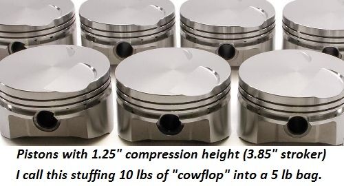
Most of the "stroker kits" available for the 351C are assembled around crankshafts having a 3.85 or 4.00 stroke, there are very few 3.75 "kits" on the market. Those 3.75 kits that are available stray from my instructions in two ways. (1) They have taken to using 6.125 length connecting rods, whereas 6.00 length connecting rods had been used in the past. This change in rod length was made as a convenience because it allows using the same pistons in the 3.75 kits as those used in the 4.00 kits. This of course means that the wrist pin shall intersect the piston's oil ring groove. (2) The second problem with all stroker kits is that none supply pistons with fully round skirts.

To build a 3.75 stroker as per my instructions shall require working with a crankshaft manufacturer to assemble a custom kit (reciprocating assembly) employing 6.00 length connecting rods and custom ordered round skirt, flat top pistons.

Reciprocating Assembly:
• Forged chromoly steel 3.75 stroke crankshaft, 2.10 diameter x 1.88 wide rod journals (to accommodate Chevy rods), internal balanced.
• 6" Chevy chromoly H-beam connecting rods (there are many choices so I'm not going to make a specific recommendation), doweled big ends, 7/16 chromoly cap screws, bushed for floating wrist pins (1.60:1 rod length to stroke ratio).
• Custom Ross round skirt flat top pistons, 1.30 or 1.32 pin height, 0.927 Chevy wrist pin.
• BHJ Dynamics damper FO-IB351C-7, steel hub and steel ring, SFI approved, Fully Bonded, 9 pounds weight, neutral balance.
• Yella Terra steel flywheel (for long-style clutches) YT9902N, 26.4 pounds, neutral balance.
• Dynamic balancing.
• Cleveite tri-metal bearings, MS1010 mains, CB826 rods.
• Bearing clearances: 0.0025 – 0.0030 Mains; 0.0021 – 0.0026 Rods.

Notes:
• 1.30 pin height is for 4.030 bore & 9.200 deck, 0.026 deck clearance.
• 1.32 pin height is for 4.000 bore & 9.215 deck, 0.019 deck clearance.

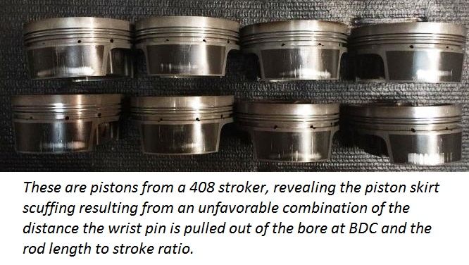
The 3.75 stroke crankshaft with a 6" connecting rod shall have a 1.6:1 rod length to stroke ratio, which is considered the lower end of the optimum range (1.6:1 to 1.7:1). The wrist pins shall not intersect the oil ring grooves. The wrist pins are pulled out of the bore at BDC LESS than they are with the OEM application. None of the rotating parts shall hit the block. The engineering is good, the engine shall be durable like an OEM engine, thus capable of lasting a long time.


Camshaft Timing Set:
Most stroker crankshafts have a "Windsor nose" but Cleveland main bearing diameters. To use a Cleveland timing set such as Rollmaster CS3091 requires a 0.375 thick (3/8) spacer for the crank nose. An alternative to the spacer is to use a timing set in which the spacer has been incorporated into the timing set's crank gear. Rollmaster makes two such timing sets, CS3130 which has a single Torrington bearing, or CS10065 which has a dual Torrington bearing assembly. If you are having a crankshaft custom made may I suggest instructing the crank company to give it Cleveland nose dimensions.

Cylinder Head:
• D3ZE open chamber 4V heads, 78.4cc chambers.
• Upgrade the heads with 2.125 intake valves.
• Open the intake valve throats to 1.70 diameter minimum; at that dimension sonic choke shall occur at 6500 rpm.
• Install Manley valves.
• Utilize head gaskets having 0.040 compressed thickness.
• The static compression ratio goal is 9.27:1.

Notes:
• An intake valve throat diameter of 1.77 will raise sonic choke to 7000 rpm.
• Intake valve, Manley Race Master or Race Flow, 2.125 diameter valve head, 5.24 length, 0.3415 stem diameter (11/32).
• Exhaust valve, Manley Severe Duty, 1.65 diameter valve head, 5.05 length, 0.3415 stem diameter (11/32).


Continued Below
.
Last edited by George P


CUSTOM ORDERED CAMSHAFTS


Flat Tappet Camshafts, Tappets, and Springs

These camshafts are flat tappet camshafts. Camshafts number 1 and number 2 are both hydraulic flat tappet cams differing mainly in the amount of valve lift they provide. Camshaft number 3 is a solid flat tappet street cam.

In order to find a high-lift hydraulic flat tappet lobe in the Bullet Cams catalog for the intake valve of camshaft number 2 it was necessary to stray a bit from the 270°/290° duration of the Cobra Jet cam, I ended up using lobes of 275°/286° duration; therefore the overlap period is not as well centered within the dwell period at TDC, but the amount of overlap is unchanged. The EVO, IVC and LSA also remain unchanged.

(1) Custom hydraulic flat tappet cam ground by Bullet Cams (lobes H270/306 and H290/312), spec: 270°/290° duration @ 0.006, 222°/240° duration @ 0.050, 0.521/0.531 net lift, 105°/115° lobe centerlines, 110° lsa, 60° overlap, EVO = 80°, IVC = 60°. Speed Pro HT900 hydraulic flat tappets.

(2) Custom hydraulic flat tappet cam ground by Bullet Cams (lobes HF275/328 and H286/328), spec: 275°/286° duration @ 0.006, 223°/230° duration @ 0.050, 0.559/0.559 net lift, 103°/117° lobe centerlines, 110° lsa, 60.5° overlap, EVO = 81°, IVC = 60.5°. Speed Pro HT900 hydraulic flat tappets.

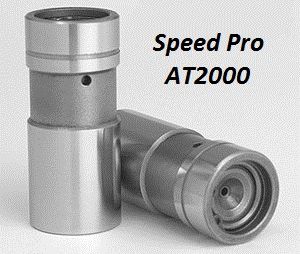
(3) Custom solid flat tappet cam ground by Bullet Cams (lobes FF271/333 and F292/334), spec: 271°/292° duration @ 0.020, 236°/256° duration @ 0.050, 0.548/0.545 net lift (0.028/0.033 lash), 105°/115° lobe centerlines, 110° lsa, 61.5° overlap, EVO = 81°, IVC = 60.5°. Speed Pro AT2000 or Crower Cams 66915X980-16P solid flat tappets. These are Boss 351 style tappets with an internal metering plate system for controlling the amount of oil flowing to the valve train.

When ordering a flat tappet cam you must specify to the cam grinder that the camshaft (a) should be ground on a best quality iron cam core, (b) it should be ground with a guaranteed 0.002" lobe taper, (c) it should receive their best quality hardening treatment (nitriding), and (d) it should receive their best quality lobe polishing.

Note:
Hydraulic Flat Tappets
- I am always careful to use and recommend parts of known quality, and which are manufactured in North America or Australia. I have used Speed Pro tappets (originally manufactured in the US by Johnson) since I was a young man. Speed Pro is now part of the Federal Mogul group of businesses, they acquire parts globally, they do not advertise where the tappets are manufactured or which company manufactures them. Therefore I am unsure if they are made to the same high quality they once were. Tappets manufactured by Johnson can be identified by the "smooth waist" (no ridges) and the single groove machined above the waist, see the picture below.


One aspect in which the performance of modern hydraulic tappets has suffered is the tappet's bleed down rate. Some cam grinders & engine building businesses are capable of checking the bleed down rate prior to shipping them to you, the extra cost for this would be worthwhile considering.

One possible valve spring for the flat tappet cams is Crane 99839, it is a single valve spring plus damper, 1.50 diameter, 354 pounds per inch spring rate. When installing this valve spring please ignore the factory specs, and adhere to these: 1.82 installed height, 114 lbs. seated force, 0.590” maximum lift.

Another possible valve spring for the flat tappet cams is PAC Racing 1900, it is a single valve spring plus damper, 1.50 diameter, 376 pounds per inch spring rate. When installing this valve spring please ignore the factory specs, and adhere to these: 1.82 installed height, 120 lbs. seated force, 0.605” maximum lift.


Roller Tappet Camshafts, Tappets, and Spring

These camshafts are roller tappet camshafts. Camshafts number 1 and number 2 are both hydraulic roller cams, only differing in the amount of valve lift they provide; camshafts number 3 and number 4 are solid roller street cams.

Camshaft number 4 intentionally strays a bit from the 270°/290° duration of the Cobra Jet cam, in order to achieve a "super hot" street cam. I ended up using lobes of 275°/284° duration; therefore the overlap period is not as well centered within the dwell period at TDC, but the amount of overlap is unchanged. The EVO, IVC and LSA also remain unchanged. This camshaft pushes the Manley 221432 valve spring close to the limits of its maximum rated valve lift.

(1) Custom hydraulic roller tappet cam ground by Bullet Cams (lobes HR270/313 and HR291/312), spec: 270°/291° duration @ 0.006, 218°/238° duration @ 0.050, 0.533/0.531 net lift, 105°/115° lobe centerlines, 110° lsa, 60.5° overlap, EVO = 80.5°, IVC = 60°. Crane 36532-16 or Morel 5323 hydraulic roller tappets.

(2) Custom hydraulic roller tappet cam ground by Bullet Cams (lobes HR270/3533 and HR291/356), spec: 270°/291° duration @ 0.006, 216°/236° duration @ 0.050, 0.603/0.607 net lift, 105°/115° lobe centerlines, 110° lsa, 60.5° overlap, EVO = 80.5°, IVC = 60°. Crane 36532-16 or Morel 5323 hydraulic roller tappets.

(3) Custom solid roller tappet cam ground by Bullet Cams (lobes R270/363 and R291/363), spec: 270°/291° duration @ 0.020, 237°/255° duration @ 0.050, 0.607/0.599 net lift (0.021/0.029 lash), 105°/115° lobe centerlines, 110° lsa, 60.5° overlap, EVO = 80.5°, IVC = 60°. Isky 3972-RHEZ solid roller tappets. The Isky tappets roll on bushings rather than needle bearings, and they are force lubricated rather than splash lubricated. Tappet bore bushings with 1/16" orifices are a necessity when utilizing solid roller tappets.

(4) Custom solid roller tappet cam ground by Bullet Cams (lobes R275/3685 and R284/370), spec: 275°/284° duration @ 0.020, 240°/248° duration @ 0.050, 0.616/0.619 net lift (0.022/0.021 lash), 103°/117° lobe centerlines, 110° lsa, 59.5° overlap, EVO = 79°, IVC = 60.5°. Isky 3972-RHEZ solid roller tappets. The Isky tappets roll on bushings rather than needle bearings, and they are force lubricated rather than splash lubricated. Tappet bore bushings with 1/16" orifices are a necessity when utilizing solid roller tappets.


When ordering a roller cam you must specify to the cam grinder that the camshaft should be ground on a core manufactured from a material which is compatible with standard OEM distributor gears (selectively austempered ductile iron) or compatible with commercially available steel distributor gears. The intention of these instructions is to avoid the use of a bronze distributor gear, due to the rapid wear rate, and due to the fine bronze particles they pollute the engine with.

If the roller cam core requires a steel distributor gear, steel distributor gears for the 351C are available from Crane Cams and Ford Racing. Crane 52970-1 is the gear for 0.500” distributor shafts; Crane 52971-1 is the gear for 0.531” distributor shafts. The gear for 0.531” shafts is also available via Ford Racing Performance Parts under part number M-12390-J. TRITEC Seal (of Swartz Creek, Michigan) has recently introduced a polymer composite distributor gear for the 351C, p.n. PP3734-BB-531. The gear is supposedly compatible with any camshaft core material, and would make a good solution for owners whose engine is currently equipped with a bronze gear.

One final word of caution regarding distributor gears, they should fit tightly on the distributor shaft, they should require a hand press (pin press) to remove and install. Some aftermarket gears do not fit tight enough, some actually slide off & on without any effort. If the gear is not tight enough on the shaft the gear's roll pin shall shear.

Note:
Hydraulic Roller Tappets
- The Ford 5.0 HO hydraulic roller tappets have been problematic in 351C applications and are therefore not recommended. They are known to collapse prematurely at high rpm, limiting the high rpm performance of the engine. There are two possible reasons for this: (1) The 351C valve train is heavier, it utilizes higher valve spring forces, and its geometry and splayed push rods subject a tappet to side thrust forces greater than the forces the 5.0 HO tappet has been designed to endure. These forces may distort the tappet body, upsetting critical internal clearances, and lead to premature collapse. It is critical that the body of a high performance hydraulic roller tappet is made sturdy enough to prevent its distortion even when subjected to higher valve spring forces and higher engine speeds. (2) The waist machined into the center of the 5.0 HO tappet is too high, it has been found to rise above the top of the tappet bore at maximum lift and dump the engine’s oil pressure in some 351C blocks, loss of oil pressure will also cause the tappet to collapse. The aftermarket hydraulic roller tappets sold by Crane Cams and Morel are known to operate reliably in Cleveland applications. The waists machined into the center of these tappets do not rise above the top of the tappet bores at maximum lift, and the tappet bodies are thicker and therefore resist distortion (with the penalty of increased weight).

A valve spring for the roller cams is Manley Nextek 221432, it is a dual valve spring plus damper, 1.53 diameter, 435 pounds per inch spring rate. When installing this valve spring please adhere to the manufacturer's specifications: 1.90 installed height, 150 lbs. seated force, 0.630” maximum lift.

If the Manley spring is installed at a height of 1.82 (the standard 351C height) then its maximum lift shall be reduced to 0.550.


COMMON ELEMENTS


Lubrication

• Install tappet bore bushings with 1/16" orifices, a do-it-yourself installation kit is available from Wydendorf Machine for a reasonable price.
• Restrict the oil to all 5 cam bearings; this requires 5 restrictors, which in turn requires two Moroso restrictor kits because each kit only contains four restrictors. The restrictor for cam bearing number 1 is installed differently than the other four. It must be installed deeply within the bearing passage, above the horizontal main oil passage, so that it is positioned between the main passage and the cam bearing. If the restrictor is not installed deep enough, it would restrict oil to main bearing number 1 of the crankshaft. The large restrictors included in the Moroso kits are not used.
• Install fully grooved main bearings. To acquire fully grooved main bearings may require using the upper shells from two sets of main bearings. This provides oil to the rod bearings throughout 360° of crankshaft rotation.
• Install an Aviaid or comparable high volume road race Pantera oil pan.
• The standard oil pump provides plenty of lubrication once tappet bore bushings are installed. The standard pump was actually a high volume pump, it had taller rotors and pumped more oil than the pumps found in Ford's other V8 engines.
• Motorcraft and Wix sell the best filters.
• The final component of the lubrication system is the oil itself. Valvoline VR1, either petroleum based or synthetic, is recommended. No additives. Use 20W50 if the engine has never been rebuilt (20W40 was the original specified oil). Use 10W30 if the engine has been rebuilt.

With these modification you can expect 80 psi cold oil pressure, and hot oil pressure should conform to Ford's specification, which is 60 psi (+/- 10 psi) by 2000 rpm; the hot oil pressure will usually be above 60 psi, it will not "droop" at higher rpm either.


Ultra-low viscosity oils (0W or 5W) can be used under the following conditions: (1) The crankshaft journals and bearing saddles must be machined to a higher level of quality than they were originally machined back in the 1970s. Taper must be less, and concentricity must be better. (2) Tappet bore bushings must be installed. (3) Use 3/4 grooved main bearings (from King Bearing) instead of fully grooved main bearings. Keep in mind hydraulic tappets may not operate properly with these low viscosity motor oils.

There is an ideal clearance in regards to optimizing a bearing's load capacity, it shall be approximately 0.001" per inch of journal diameter, but the precise clearance shall vary from engine to engine. It’s better to have more clearance than optimum than it is to have less clearance than optimum. As a bearing's clearance is reduced to less than optimum its load bearing capability rapidly decreases, whereas when a bearing's clearance is increased beyond optimum its load bearing capability decreases much more gradually. The load bearing capability of a bearing is only one of the properties affected by the bearing’s clearance. When clearances are tightened-up less oil flows into those clearances and therefore the bearings run hotter, because the oil not only lubricates the bearings, it cools the bearings as well. Here again, more clearance than optimum is better than less clearance. If bearing clearances are reduced to a degree less than those recommended above then bearing temperatures shall increase. Under these conditions consider the use of synthetic motor oil a necessity due to the superior high temperature properties of synthetic oil.


Cylinder Head and Valve Train Preparation

The work detailed below in items 1 and 2 are optional, but recommended. This moderate amount of work can make a big difference in cylinder head performance. Perform this work before refurbishing the guides and the valve seats.

(1) Valve Pockets

Clean up the valve pockets, remove casting lines and rough spots, and center the pockets on the valve guides if any aren’t centered. Smooth the guides when needed. As is true for any cylinder head, you want a smooth, well blended transition from the valve pocket to the throat, a "rounded" throat, a nice, smooth, well blended transition from the throat to the valve seat, and from the valve seat into the combustion chamber. Open the throats to the diameter specified for your application. The valve seats are normally recessed a bit, and there shall be sharp edges or “lips” around the valve seats. These “lips” must be knocked down, so that the transition from the valve seat into the combustion chamber is smooth, no sharp edges, no steps, no lips.


(2) Exhaust Ports

The 351C 4V cylinder heads have flat roofs in the exhaust valve pockets, bumps in the roofs of the exhaust ports, and port floors which “fall away” as they approach the exhaust flange. These features were placed in the exhaust ports to encourage exhaust gases to flow “downward” into cast iron exhaust manifolds which hug the engine block closely. These features are not needed if the header primaries exit straight-out from the head as the Pantera exhaust does. The exhaust valve pocket roofs should be rounded, given a typical basin shape. The bump in the exhaust port roof should be ground away.

The port floors can be filled-in (brazed) where they fall away, or commercially available “tongues” can be installed to achieve the same thing. In the case of the D1ZE cylinder head (1.71 exhaust valves) the port floor should filled-in 0.40”, leaving an exhaust port opening of approximately 2.78 square inches (1.75 x 1.60). In the case of the D3ZE cylinder head (1.65 exhaust valves) the port floor should be filled-in 0.50”, leaving an exhaust port opening of approximately 2.59 square inches (1.75 x 1.50).

(3) Valve Guides

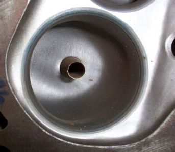
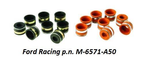
The valve guides should be repaired with bronze guide inserts. Bronze is a good material for the stems of stainless steel valves, and more durable than the original iron of the cylinder head casting. Valve guide to valve stem clearance should be 0.0010 – 0.0020 for the intake valves, and 0.0015 – 0.0025 for the exhaust valves. The top of the valve guides should be machined to 0.530 diameter to allow the installation of spring loaded elastomer valve stem seals such as Ford Racing Parts M-6571-A50 or Manley 24045-8.


(4) Valve Seats

Valve seats should be refurbished with what was once called a three-angle valve job, but today such work is often called valve seat profiling. The valve seat angle should be 45°, the intake valve seat width should be no less than 0.060, and the exhaust valve seat width no less than 0.080. Most often the person performing the valve seat work should only have to “kiss” the seats with the grinding tools to clean them up and size them properly; normally any “major” removal of metal is unwanted and unnecessary. The exception however is the intake valve seats for the D3ZE cylinder heads, adjusting the diameter of the seats for a larger valve will take a little bit more than a "kiss" with the grinding stone.

(5) Valve Spring Installation

Titanium 10° spring retainers are recommended for intake valves. Chromoly 10° spring retainers are recommended for exhaust valves, but using titanium spring retainers for the exhaust valves is OK if the extra expense is in your budget. They should be purchased from the spring manufacturer to complement their spring.

The combined weight of the exhaust valve and the exhaust valve spring retainer must always be LESS than the combined weight of the intake valve and the intake valve spring retainer. You want the intake valves to float first at high rpm thus limiting engine rpm before the exhaust valves float. Floating exhaust valves are to be avoided because the exhaust valves may hit the pistons when they float.

Steel valve spring cups are recommended because they keep the bottom of the spring precisely positioned, preventing it from walking; this will require machining the spring seats for the cup. There is some confusion at Crane regarding which spring cup to use for their 99839 flat tappet spring, the proper cup is p.n. 99455.

Typical of valve springs designed for roller cams, the Manley valve spring’s 1.90 installed height is 0.080 greater than the original dimension; it shall require the use of valves with 0.100” longer stems or further machining the valve spring seats. Utilizing valves with longer stems shall impact the rocker arm geometry, but so do high lift camshafts. You should experiment with both a standard length valve, a longer valve, and your intended rocker arms before deciding which route shall best achieve proper rocker arm geometry, because once the spring seats are machined there’s no turning back. Shim kits for adjusting rocker arm height are readily available. Raising the rocker arm a small amount with shims is much easier than lowering the rocker arm. Experimenting with rocker arm geometry can be performed with the heads removed from the engine, on your work bench, if pedestal mount rocker arms such as those recommended below are utilized.

(6) Rocker Arms

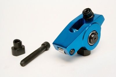
The factory stamped steel rocker arms have two things going for them, they don't add additional expense to an engine project, and they are very reliable. They were rated by Ford for up to 0.615” valve lift. They are fine for hydraulic camshaft applications having moderate valve lift. Make sure to use steel 4V fulcrums (the 2V fulcrums were made from aluminum) and secure them to the OEM slotted pedestals with ARP 5/16” bolts 641-1500 and 1/8” thick ARP washers 200-8587 to alleviate the possibility of bolt stretch. The 1/8” thick washers are required because the ARP bolts are 1/8” longer than the OEM bolts.

Most enthusiasts want to equip their engines with rollerized rocker arms however, therefore pedestal mount adjustable rocker arms manufactured by Scorpion (p.n.3224) or RM Competition would be my recommendation. The RM Competition rocker arm is a modified Harland Sharp rocker arm. There are several advantages to pedestal mount rocker arms:

• They require no machining of the cylinder head, they mount solidly to the factory cylinder head's slotted pedestal, utilizing a steel saddle and 5/16 cap screw.
• They provide adjustment of lash or hydraulic tappet compression via a push rod cup style adjuster, the same as a shaft mount rocker arm.
• They allow rocker arm geometry to be set with the cylinder head on the bench.
• Rocker arm geometry is not dependent upon push rod length; thus making it very easy to establish push rod length.
• Lash or hydraulic tappet compression does not impact rocker arm geometry.
• They promote better valve train stability than push rod guided rocker arms.


There are also two drawbacks to the pedestal mount rocker arms:

• They are fastened to the pedestal with a 5/16" cap screw. A 5/16 fastener is not what you want for racing, high valve spring force, or high rpm; but it is adequate for any street application as long as the fastener is of very high quality to alleviate the possibility of bolt stretch.
• They are only available made from billet aluminum. ALL aluminum rocker arms shall eventually fail. I recommend replacing the billet variety every 10,000 miles.

If the cylinder heads have already been machined for 7/16 studs and guide plates the Yella Terra YT6321 rocker arm is designed to bolt down solidly to the machined pedestals and thus perform as a pedestal mount rocker arm. This rocker arm's 7/16 mounting bolt makes it the choice for racing, high spring forces and high rpm. Yella Terra sells saddles of varying height to aid in setting the rocker arm's geometry. This rocker arm is double the price of those I've mentioned previously.

It is my hope that someday soon a manufacturer shall offer a steel bodied pedestal mount rocker arm. That would be the holy grail. At this date (2016) if a person wants a pedestal mount style rocker arm made from steel they have two choices; they can have a set custom made, or they can purchase NASCAR quality "individual shaft mount" rocker arm assemblies p.n.7200 from T&D Machine with their optional steel rocker arm. These rocker arm assemblies require pedestals that have been machined for 7/16 studs and guide plates; they are about triple the price of the Scorpion and RM Competition rocker arms.

(7) Push Rods

3/8 diameter pushrods manufactured from 0.080 wall seamless chromoly tubing are the final components needed to round-out this high performance valve train. Smith Brothers in Redmond Oregon is a great place to purchase custom push-rods. Other sources for push rods include Manton Pushrods in Lake Elsinore California, Manley Performance Products, and Trend Performance.

The amount of oil flowing to the valve train must be limited. I highly recommend using tappet bore bushings, the kit available from Wydendorf Machine is affordable, and the bushings are easy for the do-it-yourselfer to install. However if tappet bore bushings are not installed, oil flowing to the valve train can be limited via the pushrods in hydraulic tappet applications. Having an 0.040 restriction installed in one end of the recommended 3/8 x 0.080 push rods is one method for doing this; 5/16 push rods made from 0.116 to 0.120 wall thickness tubing, which have an approximately 0.072 passage in the middle, is another.

(8) Rocker Arm Geometry

Rudimentary rocker arm adjustment is aimed at keeping the operation of the rocker arm within four parameters; (1) the rocker arm should not contact the valve spring retainer when the valve is fully closed, (2) the rocker arm should not contact the push rod when the valve is fully open, (3) the rocker arm slot should never "bottom-out" against the fulcrum, saddle or stud at either extremity of its motion, and (4) the rocker arm tip should never bear down upon an edge of the valve tip; its sweep pattern does not have to be perfectly centered on the valve tip but it should contact the valve tip in the middle half of the valve tip's surface. You don’t want to “settle” for this however.

Geometrically ideal rocker arm geometry will set the rotational axis of the rocker arm at the same height (perpendicular) as the valve tip when the valve is 50% open. Correct geometry at the rocker tip will place the sweep of the rocker tip nearest the rocker arm at fully closed and fully open, the sweep will be furthest from the rocker arm at 50% open, and the rocker tip shall be in the middle of its sweep at approximately 25% and 75% open. This geometry will always result in the narrowest sweep pattern, although there is nothing beneficial about a narrow sweep pattern, it is just a method of evaluating the rocker arm geometry. This description of sweep pattern will be in direct opposition to many of the rocker geometry instructions you shall run across.


Ignition

The Ford Duraspark ignition is reliable, it performs well, and parts remain readily available. The Duraspark I ignition was Ford's first high output ignition, featuring dynamic dwell which charges the coil perfectly over a wide range of engine speed. Thus it is the preferred ignition (the original application was California only - 1977/1979), but the only aftermarket wiring harness available is for Duraspark II. The Duraspark I coil and the Duraspark II wiring harness require modifications to use these parts for a Duraspark I application, therefore this choice is only recommended for folks willing to perform the modifications (which aren't that difficult). The Duraspark II ignition is a simpler plug & play installation.

Duraspark I (red wire grommet) SMP LX210 ignition module and SMP FD477 coil; 0.060 plug gaps.
Duraspark II (blue wire grommet) SMP LX203 ignition module and SMP FD476 coil; 0.050 plug gaps.
Duraspark ignition wires SMP 69404

A Duraspark II wiring harness is available from Painless Wiring (p.n.30812), or American Auto Wire (p.n.500918); be sure to use the appropriate coil with the ignition module you have selected. The Duraspark I ignition does not utilize a ballast resistance.


Set the ignition timing to the following spec: 16° to 18° initial advance; 20° centrifugal advance fully in between 2800 to 3200 rpm; this equates to between 36° and 38° total advance. Street engines (operated at partial throttle) should have 10° vacuum advance connected to ported vacuum. In spite of what you may have read elsewhere, a combustion chamber of fixed design (factory Cleveland), utilized with a piston dome of fixed design (flat top), with an identical dynamic compression ratio (8.0 or less), and with a fuel of fixed octane (91 US/Canada), shall require the same ignition calibration.

If a Ford Duraspark distributor is utilized a distributor “sleeve and plate assembly” marked 10L or 10R and replacement centrifugal advance springs shall be required to properly calibrate the centrifugal advance curve. A sleeve and plate assembly with a wider “notch” can be modified to reduce the width of the notch; the proper notch width for achieving 20° centrifugal advance is 0.410”. Ignition Engineering of Anaheim California can rebuild and re-curve a Duraspark distributor for you (telephone 714-334-9143). The MSD 8477 distributor is a good substitute for the factory distributor, and the MSD magnetic pick-up is Duraspark I or Duraspark II compatible.


Induction

(1) Dual Plane Manifold - US 4V Heads
• Blue Thunder dual plane intake manifold, Pantera version (the Pantera version has a flat carburetor mounting pad).
• 4150 Holley style carburetor, 750 cfm, annular boosters, electric choke, street calibration.
• The exhaust heat passage should be welded closed unless the car shall be driven in very cold climates.
• This manifold shall give your 351C a more dramatic mid-rpm acceleration and extend its high rpm performance. All this without impacting the engine's low rpm manners. It performs better at low rpm than its large runners would lead you to believe. It has been the most popular intake manifold among 351C enthusiasts since the 1970s. Even today each production run of the manifold sells out almost immediately. How many hot rod parts can make such a claim?!


If you're a person preferring to use factory parts as much as possible, or to keep the external appearance of the engine stock, the 1970/1971 factory cast iron intake manifold, casting number D0AE-9425-L, shall be your intake manifold of choice. The manifold's carburetor flange is designed for "square bore" Holley 4150 style carburetors. The flange has 4 holes sized for a 630 cfm Autolite carburetor, the holes will need to be opened-up to 1-3/4" diameter. The exhaust heat passage should be welded closed as advised for the Blue Thunder manifold, unless the engine shall be operated in very cold climates. This manifold will not perform as well as the Blue Thunder manifold, but that is the compromise you must accept to use a factory iron manifold.


(2) Single Plane Manifold - US 4V Heads
• Holley Strip Dominator intake manifold.
• 4150 Holley style carburetor, 650 cfm, annular boosters, electric choke, street calibration.
• The Holley Strip Dominator does not perform as well at low rpm as the Blue Thunder manifold, but it performs better at high rpm ... and it LOOKS absolutely bitchen. It is only available used (eBay), and since it is in high demand amongst 351C enthusiasts it sells for quite a bit of money.
• The carb mounting pad should be milled flat for appearance and/or clearance in the Pantera.


(3) Fuel Injection
• Throttle Body Injection
• Port Injection based upon a “long runner” manifold such as the Trick Flow manifold.


(4) Individual Runner Weber Carburetion
• Aussie Speed Intake Manifold.
• The intake manifold is available in the US from Small Town Speed of McKinney, Texas. Contact Cory at (972) 989-4003.
• Weber 48 IDF carburetors (4 each).


Four Barrel Carburetors

Annular booster venturis atomize fuel better, leading to better fuel distribution within an intake manifold, more consistent air/fuel ratio from cylinder to cylinder, the ability to operate at higher compression, and the ability to make more horsepower. Select a carburetor having annular booster venturis, having vacuum secondaries, having an electric choke, and calibrated for "street performance".


In terms of size, some owners opt for a 600 to 650 cfm carburetor. Carburetors of that size will fit on an unmodified 1970/1971 iron intake manifold (D0AE-L casting number). The 351C 4V engine of 1970/1971 was equipped with a 630 cfm Autolite carburetor (model 4300A). The “smaller” carburetor is probably the best choice for a street engine equipped with a single plane intake manifold as well. Check out these 600/650 cfm carburetors:

600 cfm, vacuum secondary, modest budget: Summit Racing #M08600VS
650 cfm, vacuum secondary: Demon Carburetors #1282020VE
650 cfm, mechanical secondary: Quick Fuel Technologies #SS-650-AN

However, in terms of selecting a carburetor for a dual plane manifold with a full height plenum divider a smaller carburetor offers no better low rpm performance than a properly calibrated carburetor of larger capacity. If the engine is equipped with a dual plane manifold (full height plenum divider) its performance at higher rpm will be impacted by a 600/650 cfm carburetor. Therefore if you want the Cleveland to perform as it is capable of performing, over a wide power band encompassing idle to 6500 rpm (or 7000 rpm), then opt for a 750 cfm version. The 351 Cobra Jet engine (Q code) was equipped with a 750 cfm Motorcraft carburetor (model 4300D).

A 750cfm carburetor has 1-11/16" throttle blades and 1-3/8" venturi throats. Carburetor jetting should be approximately #68 to #70 primary jets, and approximately #80 secondary jets. There are very few choices if you limit the selection to those having annular booster venturis, an "electric choke mechanism", and "vacuum secondaries". Check out these vacuum secondary 750 cfm carburetors:

750 cfm, modest budget: Summit Racing #M08750VS
750 cfm: Demon Carburetors #1402020VE

If your preference is a mechanical secondary (aka double pumper) carburetor, check out these 750 cfm versions:

Quick Fuel Technologies #SS-750-AN
Holley #9379
Demon Carburetors #1402020

The Holley and Demon mechanical secondary carburetors do not come with electric chokes, but an electric choke can be added to either of them.


Are you looking for a good mechanical fuel pump to supply your carburetor? The Robb Mc Performance #1020 mechanical fuel pump is rated for up to 550 horsepower. Its very reminiscent of the old Carter NASCAR pump. Its a tight fit with the oil filter, you may want to do a little "relieving" with a file to make some clearance before you bolt it up permanently.

Plumb the fuel system in metal tubing as much as possible, keep the hose sections as short as possible, use a tubing bender to put smooth large radius bends in the metal tubing, do not use 90° tubing fittings. Plumb the pump suction in ½" (AN-8) tubing or hose and plumb the pump discharge in 3/8" (AN-6) or ½” (AN-8) tubing or hose. Install a high flow fuel "pre-filter" designed for the fuel pump inlet (75 to 150 micron) and install a high flow fuel "post-filter" designed for the fuel pump outlet (10 microns for fuel injection or 40 microns for a carburetor).


Pantera Exhaust

Pat Mical headers, PIM headers, or Hall GTS headers; any of the 3 connected to Hall GTS tail pipes. The diameter of the header primaries should be 110% the size of the exhaust valves, 1.65 exhaust valves need 1-7/8" OD primaries; 1.71 exhaust valves need 2" OD primaries.


Tri-Y headers, if available for your application, best complement dual plane or individual runner induction, and are best suited for street and road racing applications. The headers pictured below are manufactured in Australia for Australian Falcon applications.


BIG HORSEPOWER - THE SUPER COBRA JET


For those who want to build a high horsepower street engine may I suggest starting with the 377 CJR long block as a foundation. Increase the static compression ratio as far as you feel safe to do so. I would recommend 8:1 dynamic compression, which is equivalent to 9.63:1 static compression. Perform the valve pocket and exhaust port work explained above. Utilize roller camshaft number 4. For induction choose the Holley Strip Dominator intake manifold and a 850 cfm annular booster carburetor (Holley 9380 or QFT SS-850-AN). Tune the carburetor well. This induction system will yield about 90% volumetric efficiency at peak horsepower.


To achieve the best horsepower the Pantera exhaust system will also require mufflers providing lower back pressure than the ANSA mufflers; Pantera owners may want to check-out the Flow Master #8425152 Super 10 Series muffler and the Cherry Bomb #7425 Extreme Series muffler.


COMMON CLEVELAND ASSEMBLY ERRORS


(1) The dynamic compression ratio is miscalculated, set too high for the fuel octane the owner planned to use.
(2) The No.1 cam bearing is installed too deep into the block.
(3) Improper head gasket orientation.


(4) Bearing clearances are too tight (i.e. set to factory spec).
(5) When replacing the rear crankshaft rope seal with a neoprene seal, the pin in the seal groove of the No.5 main bearing cap is not removed
(6) The wrong thermostat is installed
(7) The brass orifice below the thermostat is missing


(8) The OEM oil pump drive shaft (intermediate shaft) has been replaced with a “heavy duty” shaft.
(9) The distributor drive gear is too loose on the distributor shaft.
(10) The owner has been “talked into” using a brass distributor drive gear
(11) The water pump “recirculation passage” is not drilled-out in some aftermarket water pumps.
(12) Ford 5.0 HO hydraulic roller tappets have been utilized.
(13) Improper hydraulic tappet adjustment (compression); normally excessive (1/4 to 3/8 turn is good).
(14) Valve stem to valve guide clearance too tight.
(15) Materials chosen for valve seat inserts are incompatible with stainless valves (needs iron or beryllium copper).
(16) Camshaft “lobe centerline separation angle” (i.e. LSA) is too tight, creating 3 problems
• Excessive overlap for a large canted valve engine thus degrading low rpm power and drivability
• The exhaust valve opens too late thus causing power to fall-off prematurely at high rpm
• The intake valve closes too early thus boosting dynamic compression excessively
(17) Improper break-in of flat tappet camshaft (under-lubricated)
(18) Improper oil has been selected. Read Here: 540 Rat Blog on Motor Oil
(19) Oil additives which diminish the wear properties of oil have been used (this includes ZDDP additives)
(20) Improper break-in of rings, creates oil burning (over-lubricated during assembly)
(21) Excessive connecting rod side gap, creates oil burning (should be 0.010 to 0.020)


These ideas are presented to kindle thought.

“I cannot teach anybody anything. I can only make them think” ― Socrates

I've had a life-long interest in the Cleveland Ford, I believe these are the most intelligently conceived high performance Cleveland street engines I've penned up to this date (2016). Time will tell if anyone agrees. Thanks for reading down this far. If you have any questions, comments, or constructive criticisms please feel welcome to post a reply.

Debbie and I love you guys.

Attachments

Images (1)
  • _me_deb
Last edited by George P
George & Debbie,
For me, being a new member of this forum. I can't thank you enough. Your knowledge/experience is greatly appreciated. All your posts have been very informative. I can't say you are wrong in any of the explanations you've posted. I can say I will take and use them to find a engine builder in my area to do any work needed. And if I can't find one, you will be hearing from me!Smiler Thanks again to both of you for all you do to keep the Pantera community going.

Kenny
Hay WA
George & Debbie
Woooow what a job to build this source of information on new and extended stage!
I was always studying your pages in depth, and ALSO appreciated you swift responses on my "personal" question!
As Europe is speeding up on Panteras - well prices go up - we need MUCH MORE insight - you provided LONG TERM insight and HELP!!
TXXX for this

Matthias

Dr.-Ing. Matthias Gruetzner/Stuttgart/Germany
VIN 4907
Minimizing Friction (improves BSFC)

• Piston ring drag on the cylinder walls is a major source of power-robbing friction. Modern thin piston rings are not only designed to seal better, they are also designed to reduce friction, via lower tension and reduced contact patch. The Ross pistons I've recommended below are designed for modern "thin" piston rings.
• The operating friction of engines utilizing the 3.5 stroke OEM crankshaft can be reduced by utilizing longer (351W length) connecting rods.

Is this an economical way to "free up" horse power?
What I'm contemplating is...Resize stock rods,upgrade to ARP hardware and Ross stocked pistons or purchase Windsor I-beams and Ross pistons with a custom compression height?
Thank you Joe.

Monty,

People spend a lot of money on "hot rod parts" to achieve more horsepower, but also ruin the enjoyment of driving the car. I love horsepower that can be gained without ruining the drivability of an engine. Although attaining such horsepower can cost as much as purchasing those "hot rod parts" I consider it free horsepower because it cost nothing in terms of drivability, and it doesn't impact my enjoyment in driving the car.

The Ross pistons are more expensive than other pistons, BUT they are the least expensive forged - flat top - round skirt pistons on the market. If they are being added to a block originally equipped with dished pistons, that's all the better. FYI the "off-the-shelf" Ross pistons have a taller pin height, for more compression, so keep an eye on the dynamic compression.

A good quality OEM thickness 5/64” plasma moly ring set using a barrel faced ductile iron top ring will cost about $100 to $120. A top-of-the-line "thin" 1/16” chromium nitride faced ring set using a steel top ring will cost $280 to $380. So improving the technology of the piston rings will cost $280 or less.

I believe that combination is worth every additional penny it costs.

The rods are another story. The 351W Eagle H beam rods are $500. The fact that they are made of chromoly steel, have doweled caps, and have 7/16 cap screws fastening the caps makes them a big improvement in strength over the factory rods. Their extra length means they reduce thrust on the cylinder walls (same as the round skirt pistons), they prevent the wrist pin from being pulled out of the bore at BDC, and the piston has a shorter pin height (needed because the connecting rod is longer). The piston having a shorter pin height means the piston will "rock" less within the bore. This is all good engineering which appeals to my German nature. That's worth $500 to me alone, the fact that it frees-up horsepower too is just icing on the cake. Now, the majority of 351C engines are operating just fine with factory connecting rods, so I don't expect everyone to feel the same way I do in this regard. But ... yes ... your $500 expenditure for the connecting rods purchases not only superior engineering and strength, but more "free horsepower" as well.

I can't express it better at this moment.
Last edited by George P
I was initially thinking about less expensive I beam W rods w/press fit pins. I suppose that if one changes to W rods w/custom pistons it then it makes sense to go all the way and buy H beam rods w/floating pins."In for a penny. In for a pound."
At some point I need to decide when I've been $200'd to death and say enough is good enough. Can't blow the whole budget on the engine alone.
Thanks for the direction.
Excellent information George. Very informative.


quote:
Originally posted by wpl:
why not a factory LS-3 or LT-4
you have the reliability and much more hp for the $$$$$


Call me crazy, but I have yet to see any of these "cost efficient" modern conversions on here provide a full break down of the parts needed to do the change or mention the cost of headaches and individual research and development. I can't see how with the technological advancements in Cleveland stroker kits, heads and intakes not requiring any change to exhaust, shifters, motor mounts, accessories, engine management systems etc can be more costly than being required to change all of those systems.

Scott has had some of the most success with his modernized conversion and he has put way more hours and R&D than most of owners would be willing to do in order to make the car the way he wants it. I still don't see all of his work being less money than a good quality Cleveland build. More powerful and efficient possibly.
quote:
why not a factory LS-3 or LT-4


No ill will for other's opinions but....For me its the same reason I want to see a Flathead or SBF in a '32 ford. Chevy powered Cobra? Dare I say GT40? Henry II should roll over....Same goes for a Pantera/Mustang/Torino or "ugh" Pinto. 351C power for me please.
All I can say is that its not "Ford Power". That's why not.
Where is the thread for "unleashing the performance capabilities of LS engines".
I think one made a wrong turn at Albequerque
I’ve really enjoyed reading all the various guides on this forum, particularly George’s, but this one has me intrigued.

I’m restoring an ‘70 Mach 1 Mustang, (sorry Pantera people, maybe one of your sexy roadsters will be my next project) which somewhere along the way had it’s 2v 351w swapped out for a 2v 72/73 Cleveland (D2AE-CA), as I’m in the U.K. I decided to just roll with this and rebuild it myself to something a little more fun.
I’ve just stripped off it’s 2bbl Manifold and heads, (gasket failure and a little surface rust found in 2 bores, but never been rebored previously so lucky in that respect).

I’m leaning towards the standard stroke variant, as I have a 4mab crank with a touch of orange paint and the Brinell testing mark on the 1st counterweight and quite like the idea of keeping and using this strong old devil to help keep to a healthy budget.
With the help of EBay I’ve picked up a set of the 73 4v heads which i’ll Be shipping to the U.K. along with a few other bits as soon as I have them all together.

I’m thinking of going with the factory cast iron manifold and grinding out the bores, and I need to get a new transmission (thinking 4 speed Toploader) as the one I got with the car went walkies somewhere between the port and arriving with me.

I’ll be hooking it up with a Holley 3310-4 that I plan on converting to a 4150 to provide the high airflow numbers.

I’m quite curious about the cam’s though as that’s a lot of choice there, George would your custom cam complement a cast iron manifold set up or would it be somewhat limited without the improvement provided by the Blue Thunder?
quote:
Originally posted by Husker:
As I recall the Clevelands replaced the Windors for the 1970 model year.

They did indeed, according to the Marti report it was outfitted with a Windsor and from what I can gather some early H code ‘70s (mine was September 69) had Windsor’s, all the 4v 351’s were Clevelands.
Still I don’t see it as any disadvantage the 351c is a great engine and the Cleveland’s history and troubles in the USA before its Aussie rebirth is much more interesting to me.
M code and H code engines for about the first half of the 1970 production year were 351W, not 351C. The Clevelands started showing up in either December 1969 or January 1970. I know guys who were waiting to order Mustangs until they were available.

The earliest casting dates on Cleveland parts is about August 1969 (there are some late July heads) and it takes 3 months between the time the parts are cast and when the engines assembled from those castings arrive in showrooms.

John the streetable cams, with early opening exhaust valves (to contend with cast iron manifolds and mufflers), relatively late opening intake valves, and low overlap can contend with a wide range of engines. I can spec other grinds with less overlap than the proposed Cobra Jet cam in this thread.

If you haven't purchased pistons yet, you may want to consider the Sealed Power or Ross pistons with pop-up domes as they get you closer to 10:1 static compression and open up a wider variety of more "streetable" camshaft grinds to choose from (less overlap, later opening intake valve).

Things to ponder.
quote:
Originally posted by George P:
M code and H code engines for about the first half of the 1970 production year were 351W, not 351C. The Clevelands started showing up in either December 1969 or January 1970. I know guys who were waiting to order Mustangs until they were available.

The earliest casting dates on Cleveland parts is about August 1969 (there are some late July heads) and it takes 3 months between the time the parts are cast and when the engines assembled from those castings arrive in showrooms.

John the streetable cams, with early opening exhaust valves (to contend with cast iron manifolds and mufflers), relatively late opening intake valves, and low overlap can contend with a wide range of engines. I can spec other grinds with less overlap than the proposed Cobra Jet cam in this thread.

If you haven't purchased pistons yet, you may want to consider the Sealed Power or Ross pistons with pop-up domes as they get you closer to 10:1 static compression and open up a wider variety of more "streetable" camshaft grinds to choose from (less overlap, later opening intake valve).

Things to ponder.

Thanks George, things to ponder indeed.

I’d be delighted for you to spec a cam, and any advice towards what pistons and valve sizes etc beyond the extraordinarily comprehensive articles you’ve got on here would also be very gratefully received.

I’ve not got so far as buying the pistons yet, as I’m taking the block to be looked at and see if I can get away with a hone or need a full rebore. I’m thinking depending on the dome I’ll be able to get away with less milling of the heads.

Federal Mogul Powertrain have a office downstairs from one of the offices I work at, I’ll try to cultivate a friend there and see if they can get me the sealed power pistons and rings at a reasonable cost.

Btw, I’m definitely going to follow your oil control advice, seems to me to be a great investment in durability.
Hello folks,
I have been privileged to see why some have gone down the road of conversion, its safer when you see the end result of a cheap and questionable build, the one I saw was a hack crank job that a goober weld was used in place of mallory metal to balance,it came loose and tore up / cracked the engine.
So instead of realizing it was a poor choice and doing a stand up build, they have done the safe move of putting in a warrantied vette motor???? Sound familiar. Just wish they would quit minimizing the 351 Cleveland
!
I have a 351 that I lost due to a valve coming off the stem, Great running engine for 38yrs. wow!
I have on a stand the same engine with an approx 620hp/carb and pump gas. I have no worry's if this engine will run well as I have many builds that I own that are running well 25 yr after the build.
The costs are a fraction of a crate engine but require a real commitment in time and knowledge.
The best parts are always used and payoff over time.
We have a treasure in this site and George for help and incite to support our efforts on on engine assembly.
Got to agree George is a treasure, I’ve been reading and re-reading the main how tos on here in combination with a lot of other Cleveland literature, and feel I’ve learned quite a bit more here than elsewhere.


So looking at the various pop ups available from Ross via Summit, looks like the w80552 and w80662 are my options both are -12cc which assuming a 4.030 overbore and no/minor skimming of the heads will give me ~10.5 static compression.
Here in the UK I can get 98/99 RON fuel from most petrol stations at a modest increase in cost, would I be correct in assuming that pushing the static ratio up and switching to higher octane gas would be preferable to further mitigate detonation issues given the open chambers on the 73 heads?
What sort of cam would be best to produce a high good streetable/occasional track day car looking at this scenario, something closer to the original Boss 351 grinds?
I’m not stuck on either solid or hydraulics either and would happily use whatever gives me a nice durable engine with serious punch.
The cylinder walls are too thin for anything greater than about 8.0:1 dynamic compression; i.e. fuel compatible with 91 octane pump gas (US & Canada) or 95 octane pump gas (Europe & Australia). An engine operating at 8.0:1 dynamic compression on 91 octane fuel, operated at wide open throttle is pushing the limits of the cylinder walls. So build the engine based on that limitation, no matter how high the octane of the pump gas which is available to you.

The amount of static compression the engine can use is dependent upon when the intake valve closes. A "bigger" cam can usually use more static compression. An engine can use about 11.0:1 static if the intake valve closes at 76 degrees ABDC.

Also be aware that raising compression is a situation of diminishing returns. Less horsepower is gained going from 10:1 to 11:1, than was gained going from 9:1 to 10:1. This is because the engine has to work harder to compress the fuel/air higher.

Finally, in my experience, open chamber heads are no more prone to detonation than quench heads.

Technically a solid roller tappet cam will make the biggest horsepower, but I'm a bit reluctant to recommend it. There are no rev-kits available for the 351C, and without a rev-kit the roller tappets take quite a beating due to the lash clearance. I can explain what I would do to operate a solid tappet roller cam ... if you wish. But the hydraulic roller tappet cam is a better bet for engine longevity because there is no lash clearance. A Cleveland for the street needs lots of lift but conservative duration to keep the overlap at or less than 60 degrees.

Here's what I consider the biggest "street cam"
(i.e. the valve events bump up against all of my valve event limits)

286°/290° duration at 0.006
232°/236° duration at 0.050 (approximately)
Lift will be limited by the valve spring.
The spring I've been recommending has a max lift of 0.630 inch.
114° LSA, 60° overlap
index the cam +1° (113° ICL)
This cam can use 10.8:1 static compression

That's a pretty bitchen cam. Too big for me at my age.
I like the sound of that bitchen cam very much, thanks for info George.

I’ll build with 91octane/95ron in mind as you suggest, last thing I want is blow holes in the cylinders.

And from there probably land somewhere in the 10.5 range static compression wise.

I’m thinking hydraulic roller at your suggestion there and I’ll take a look at my options with that in mind.

I did have a good look around the web for a rev kit, however despite many hints and allegations on various old forums I couldn’t find one, looks like the occasional old one ends up on ebay but nothing to rely on.

Now, that being said I think I’d love to hear how you would use the solid roller setup if only for educational purposes, as one of the very best things about your posting is the detailed reasoning behind the decisions you’d make. It really helps to illuminate so many of the pitfalls around how these old hunks of iron make real power without falling apart dramatically when doing so, and what compromises might be necessary to get there.
John, in autocrossing (also known as parking-lot racing), I got a backfire on the starting grid with a friend's Pantera that wasn't sufficiently warmed up. The 351-C had been rebuilt with 11:1 c.r, bored 0.030" over, big solid lifter cam & Holley carb, and needed 102 octane fuel to run without detonation. Immediately after the little backfire, water was seen running out one exhaust pipe. A teardown showed a piece of cylinder wall about 1" x 1" had cracked and blown clear into the water jacket. The retrieved piece showed a cylinder wall thickness of only 0.050"! For performance use, cylinder walls need at least 0.150" and more is better! Chev guys like to see 0.200"- no 351-C ever had such thick walls when new!

Lesson #1 learned: do NOT bore a 351-C AT ALL unless you first run a cylinder wall thickness check. This block had a shifted casting core on that cylinder.

Lesson #2: As you found out, stock valves are made in two pieces and WILL separate at the head-to-stem weld if overstressed. And 'overstressing' is ridiculously easy on a completely stock 351-C. Air-cooled VW valves are made the same way. Use ONLY one-piece valves which require single-groove keepers.

Lesson #3: I also suggest a fully baffled 10-qt oil pan or you run the risk of wiping out crank bearings from cornering forces. A friend lost a connecting rod after only a dozen laps of open-track road racing with a stock pan full of oil. Good luck on your next 351-C engine build.
Personally, I would use 10:1 static compression ratio as the maximum. I wouldn't worry too much about whether you have 9.5 or 10.

The point is, you want to run higher then the 8.0:1 in the stock open head engines.

That's my opinion on a rebuild.


As far as a camshaft, YOU need to determine what the definition of a "street engine" is. "We" have all sorts of race and former race engines being run on street registered and street driven cars.

The old definition of "street driven" on cars like Panteras, if not all current vehicles has changed significantly since the '60s and '70s.

Few are going to use any of these cars as "everyday transportation".

In that old definition where you need to worry about being in city type traffic of bumper to bumper then I agree with GP's limit of camshaft timing.

Even that is on the "racy side" but in this limited use existence of just taking the car to a car convention, a high speed on the track event or even a "cars and coffee" thing down near the beach, limiting the cam timing is much less of a concern.

For one thing at least with a Pantera, you don't need to worry about the operation of an automatic transmission being effected by the camshaft timing.


To select a mechanical roller lifter camshaft is sentencing yourself to a "race car" type maintenance of almost daily readjustment of the valve train.

There definitely are cars running them out there but those are really falling into the definition of a "Pro-street" car.

If those types of maintenance issues don't concern you and you just want the maximum amount of hp that you can get, then yes, go for it.


Hydraulic roller lifter cams have become much more dependable and there is a greater variety of "off the shelf grinds" for you to select right now.

They are going to give you closer to a maximum hp then a flat tappet cam but the amount you gain is always going to be debatable.

Aftermarket kit components in the past or should I say initially left a lot to be desired on a dependability consideration but there are a lot of them running around the streets now with much less issue.

The main consideration is going to be the initial cost vs. a convention flat tappet cam.


I personally like solid lifter/flat tappet cams. I know how to deal with them better then the other alternatives and find that they are a better compromise as far as approaching maximum hp in a street driven car with high dependability.


I would however recommend a hydraulic lifter flat tappet cam for a true street car.

Then you could just jump into the thing, drive it anywhere and not worry about weather changes, finding racing gas along the road, and even let your daughter drive the car down to the "hamburger stand" without too much worry of being able to drive the car without a nervous break down.

By far the single most significant factor in determining the character of the car is the camshaft that you select.

Although I agree with George on the recommended timing, I'd say that you can go hotter on the cam then 236 @ 50.

What you really want to do is to limit the overlap timing on the cam to under ABOUT 70 degrees and you want a valve lift that is going to let these heads work which is going to be over .550 to as much as .625.

These 4v heads were designed to work at around .600 lift but in addition they need greater overlap then a stock camshaft. Lift and duration alone won't do it.


The more that you ask others, the more that you are going to find that the camshaft selected and LIKED is a very personal thing.


In practical terms it makes little sense to build and engine in a "street car" to run in the 8,000rpm area. If that is your criteria, then you have crossed over into the "Pro street" category.

It has and is done but it is an entirely different animal with different issues.


You actually would be better off "interviewing each CAR", experiencing how they sounded and their idle manners before you selected something.

How you are going to do that, I have no idea, but good luck on that one.
Last edited by panteradoug
quote:
Originally posted by Bosswrench:
John, in autocrossing (also known as parking-lot racing), I got a backfire on the starting grid with a friend's Pantera that wasn't sufficiently warmed up. The 351-C had been rebuilt with 11:1 c.r, bored 0.030" over, big solid lifter cam & Holley carb, and needed 102 octane fuel to run without detonation. Immediately after the little backfire, water was seen running out one exhaust pipe. A teardown showed a piece of cylinder wall about 1" x 1" had cracked and blown clear into the water jacket. The retrieved piece showed a cylinder wall thickness of only 0.050"! For performance use, cylinder walls need at least 0.150" and more is better! Chev guys like to see 0.200"- no 351-C ever had such thick walls when new!

Lesson #1 learned: do NOT bore a 351-C AT ALL unless you first run a cylinder wall thickness check. This block had a shifted casting core on that cylinder.

Lesson #2: As you found out, stock valves are made in two pieces and WILL separate at the head-to-stem weld if overstressed. And 'overstressing' is ridiculously easy on a completely stock 351-C. Air-cooled VW valves are made the same way. Use ONLY one-piece valves which require single-groove keepers.

Lesson #3: I also suggest a fully baffled 10-qt oil pan or you run the risk of wiping out crank bearings from cornering forces. A friend lost a connecting rod after only a dozen laps of open-track road racing with a stock pan full of oil. Good luck on your next 351-C engine build.


I’m definitely building a library of lessons gleaned from you guys here. And having great fun reading the various anecdotes of where things have gone wrong. I can’t imagine how it must have felt to find a chunk of cylinder like that.

I promise to have the block fully sonic tested before I overbore, I know I might be able to leave it stock with just a hone, but I’m tempted to get it done along with line honing and decking so that I’ve got everything nailed down and blueprinted as best I can.

Valves, I will definitely go with the single groove, whilst I have it apart it would be madness to avoid drawing the right lessons from Sick Cats experiences.

I was looking at a road race pan, from some guys called High Energy from Australia, which is an 8 litre similar to the moroso offering, and mating it with a pressurised oil reserve unit.

Also considering getting another bare block from Aus, (as they are scandalously cheap and my company has a great shipping partner there) to use for checking fitment and clearances.
quote:
Originally posted by PanteraDoug:
Personally, I would use 10:1 static compression ratio as the maximum. I wouldn't worry too much about whether you have 9.5 or 10.

The point is, you want to run higher then the 8.0:1 in the stock open head engines.

That's my opinion on a rebuild.


As far as a camshaft, YOU need to determine what the definition of a "street engine" is. "We" have all sorts of race and former race engines being run on street registered and street driven cars.

The old definition of "street driven" on cars like Panteras, if not all current vehicles has changed significantly since the '60s and '70s.

Few are going to use any of these cars as "everyday transportation".

In that old definition where you need to worry about being in city type traffic of bumper to bumper then I agree with GP's limit of camshaft timing.

Even that is on the "racy side" but in this limited use existance of just taking the car to a car convention, a high speed on the track event or even a "cars and coffee" thing down near the beach, limiting the cam timing is much less of a concern.

For one thing at least with a Pantera, you don't need to worry about the operation of an automatic transmission being effected by the camshaft timing.


To select a mechanical lifter camshaft is sentencing yourself to a "race car" type maintenance of almost daily readjustment of the valve train.

There definitely cars running them out there but those are really falling into the definition of a "Pro-street" car.

If those types of maintenance issues don't concern you and you just want the maximum amount of hp that you can get, then yes, go for it.


Hydraulic roller lifter cams have become more dependable and there is a greater variety of "off the shelf grinds" for you to select right now.

They are going to give you closer to a maximum hp then a flat tappet cam but the amount you gain is always going to be debatable.

Aftermarket kit components in the past or should I say initially left a lot to be desired on a dependability consideration but there are a lot of them running around the streets now with much less issue.

The main consideration is going to be the initial cost vs. a convention flat tappet cam.


I personally like solid lifter/flat tappet cams. I know how to deal with them better then the other alternatives and find that they are a better compromise as far as approaching maximum hp in a street driven car with high dependability.


I would however recommend a hydraulic lifter flat tappet cam for a true street car.

Then you could just jump into the thing, drive it anywhere and not worry about weather changes, finding racing gas along the road, and even let your daughter drive the car down to the "hamburger stand" without too much worry of being able to drive the car without a nervous break down.

By far the single most significant factor in determining the character of the car is the camshaft that you select.

Although I agree with George on the recommended timing, I'd say that you can go hotter on the cam then 236 @ 50.

What you really want to do is to limit the overlap timing on the cam to under ABOUT 70 degrees and you want a valve lift that is going to let these heads work which is going to be over .550 to as much as .625.

These 4v heads were designed to work at around .600 lift.


The more that you ask others, the more that you are going to find that the camshaft selected and LIKED is a very personal thing.

You actually would be better off "interviewing each CAR", experiencing how they sounded and their idle manners before you selected something.

How you are going to do that, I have no idea, but good luck on that one.


I’m not wedded to any particular static ratio so for me, I think I can live happily with ~9.5 How I can achieve it with flat tops and some milling of the head and deck or domes, I’ll keep working on figuring out, but it looks that using flat tops instead of Ross pop ups may save roughly enough to cover a hydraulic roller setup.

I very much appreciate what you are saying about Street.
When looking at Street for me, I am thinking probably roughly similar to you, that it won’t need lash adjustments at the weekend, won’t have a super rough idle, won’t be temperamentally unreliable if used to as a daily driver for a few days whilst my BMW is undergoing repairs or whatever, but it will have the capability to unleash some serious torque and HP, and maybe enjoyably compete in vintage style racing events, hill climbs and the likes, and still remain a reasonably mannered cruiser for the occasional long journey into the Scottish highlands or across Europe.

I’m not building the car as a daily driver, and again apologies gents that it’s a Mustang rather than a Pantera, much more a weekend fun car, something to be driven though rather than simply looked at.

With this I also don’t need to be worried about the auto trans, as i’m going to mate it up to a Dave Kee rebuilt RUG-JA big block toploader.

With the wise words of you and George in my mind Doug, I’m leaning very heavily towards the hydraulic roller setup and I’m going to take a more serious look at what sort of compromises and financial travails that entails during the next couple of weeks.

As for interviewing the cars to understand the cam selection, well it might have to wait until next year now, but I’ll find a way, might make for a fun vacation.
(I was also considering picking up a couple of OEM style cams from Rock auto or summit to get a feel for the changes in power bands and idle, going hydraulic might make that an expensive proposition though I suppose.)
I had a closed chamber iron head Cleveland with TRW popup pistons,compression ratio of around 11.8:1 in my 68 GT 350 for ten years or so.

I tried several cams, headers and
induction set ups.

It could never produce the power like the,current engine in my Pantera does. The chassis just created breathing issues that could not be overcome.

It needed bigger tube headers, the Webers were too close to the hood, etc.

It is also noticeably heavier then the original 302 was.

My final decision was that it wasn't worth it in a Mustang chassis.

I will say that I never blew it up either even at .030 over, although it seemed at times I was trying to really hard?


In that car I went back to the original 302 block, 4v Windsor heads, race ported with 1.94/1.60 valves. 1-3/4 tube headers, 236 @ .050 solid lifter camshaft and a 10.3:1 compression with a 347 kit and a 2x4 Holley induction.

That run in front of a Doug Nash 4+1 speed, now called a Richmond 5 speed. The 3.26 first gear does help.

It works much better then the Cleveland ever did and is about 100 pounds lighter BUT as a matter of fact, it needs more cam.

This one isn't enough. It needs to go to 1.7 ratio rocker arms for more lift.

http://www.compcams.com/Compan...s.aspx?csid=820&sb=2 Wink


The Cleveland however seems like it was made for a Pantera? Everything that makes it a killer engine fits in the car. 180 degree headers with 2" primaries, Ford A3 high port heads, Weber 48 ida carbs with 5" stacks.

I do have a lot of cam in it though. A Compcams solid lifter 294s.

http://www.compcams.com/Compan...s.aspx?csid=861&sb=2

George could give me permanent KP as a result but the way that I use the car it seems perfect?

It screams like an F1 car right off of idle.


I learned my lesson with compression ratio. My Pantera engine is a 9.5 engine.

Don't believe this business of blowing compression out of the exhaust with cam timing. Simply put, it doesn't work.

Not unless you go to RADICALLY MORE overlap where you actually hear the exhausts spitting at idle. Where that is, I'm not sure exactly but probably with a race type only cam with overlap in the mid '80s?


No matter what you do it is still the static compression ratio that determines octane since it is what determines the internal cylinder pressures.

Octane is a measure of the compressability of fuel. The higher it is, the more difficult it is to make it explode by compressing it.

As an example, diesel fuel has a much lower octane rating making it much easier to explode it by compression, which is essentially how a diesel engine runs.


I will also point out that the same camshaft in different cars, seems different.

The same cam that is in a Pantera will seem calmer in a Mustang or more radical in a Pantera.


Ford was on the right track when they produced the CJ cam for the Cleveland. The problem was that they retarded the timing in the cam itself for production and it needs more lift, a lot more to make the heads work.

George's idea of making the CJ better, or maybe correcting those oversights is actually a very good idea.

The stock sound of that CJ cam through the Pantera's Ansa mufflers actually sounds quite nice and muscular. It is not out of character to the car at all.

IF you go that route, contact the cam manufacturer and ask if the timing in their "replica" CJ cam is retarded as well.

Other than that have a great time traveling to check out how all the different cams sound? Big Grin
Last edited by panteradoug
You’re making me like the sound of the Pantera more and more Doug Big Grin

I should be able to get some pretty decent hooker headers into the ‘70 stang which might alleviate some of the problems you note, I probably still won’t get what you get from it thanks to weight and weight distribution as much as anything else, and I might actually drop in a 2v Windsor (was original H code) and keep the 351c aside when I eventually sell up. (I’ve half an eye on restoring a 71 convertible eventually and that’s got quite a bit more space under the hood a Pantera being way out of my price range for now)

Just to pull back a little to something George said in the original post:

‘It is my hope that someday soon a manufacturer shall offer a steel bodied pedestal mount rocker arm.’

In lieu of that eventually happening, I’ve come across an Aussie bunch called Crow Cams offering steel roller rockers for the Cleveland (screw in stud and plate, 7/16, 1.7 ratio, ironically more info on eBay than their site) anyone had any experience with these fellows? As I guess they’d well outlast the Aluminium versions and the price looks okay.
John, 2024-extruded aluminum roller rockers will work just fine on the street, with the following provisos: 1- use brand name assemblies. Cheap far-east copies are of doubtful metallurgy; we call the stuff 'chinesium'. 2- Use NON-racing valve springs and 3- a 6500 rpm redline. Exceed either the spring strength or rpms very much, for very long or very often, and steel roller rockers (several good makers) are almost mandatory. Most 'steel' rockers are investment-cast-stainess, by the way.
i don't think anyone's talking about controlling DCR during the overlap period (intake valve opening) but rather when the intake valve closes ... when the actual physical act of compressing whatever is in the cylinder begins and the exhaust valve has been closed for quite some time

but as far as overlap barking at idle, Yes the Crane F238 barks sharply when the throttle is snapped

by no means a nice driving cam, the F238 trades idle & low speed characteristics for high speed scavenging which i believe it does pretty darn good! FWIW the F238 has less lift more overlap than the F246
John H,

Aftermarket rocker arms fall into two categories; (1) those that mount on studs and are laterally positioned by their push rods using guide plates, (2) those that are mounted rigidly to the cylinder head and are laterally positioned by the orientation of their mounting system. The second type of rocker arm is described by several names: individual shaft mount, pedestal mount, saddle mount, or bolt down. Whatever they may be called they have two things in common, they mount rigidly to the cylinder head and they are equipped with threaded push-rod cup style adjusters for solid tappet lash adjustment or hydraulic tappet compression adjustment.

Rigidly mounted rocker arms are preferred because they have several advantages in comparison to stud mounted rocker arms: rocker arm geometry is not dependent upon the length of the push rod, rocker arm geometry is not altered during lash adjustment, rocker arm geometry is easier to set because it can be set while the cylinder head is sitting on a work bench, and the mounting system is more stable thus eliminating any rocker arm induced valve train instability problems. T&D rocker arms are supplied with a "Stand Height Gage" to aid in setting rocker arm geometry.

Pressurized oil is supplied to all rocker arms via the pushrod. Most rocker companies have a through hole in the push rod cup or the push rod cup adjuster screw. The through hole allows oil to spray out the top of the cup or the adjuster, the oil hits the valve cover, and then rains down on the rocker arms.

By contrast T&D rocker arms are internally lubricated. Oil supplied by the push rod to the push rod cup adjuster screw makes a 90° turn and enters the rocker body itself. An oil passage within the rocker arm body routes the oil between the two bearings in the rocker and then out to the opposite end of the rocker arm where it sprays against the backside of the roller tip. T&D rocker arms thus have engine oil pressure right to the fulcrum bearings; bearing issues are a rare occurrence with T&D rocker arms.

All aluminum rocker arms will eventually fail from fatigue, even those made from billet aluminum. This is true with anything made of aluminum that cycles. Aluminum rocker arm failure is predominantly a function of cycle time. They cycle faster at high rpm, but even at idle the rocker arms are being cycled. Valve lift has nothing to do with rocker fatigue what so ever. Valve spring force should not be a significant factor since the topic at hand is performance street engines which are generally limited to 400 pounds over the nose (or less) in the name of valve train longevity.

T&D aluminum rocker arms have the highest cycle time in the rocker arm industry ... BUT... T&D rocker arms are also the only rigidly mounted rocker arms which at this time are available optionally with a steel rocker arm body for the best possible longevity. While other rocker arm companies manufacture stud mounted rocker arms made of cast steel, T&D’s steel rocker arm bodies are machined from billet chromoly steel, their cycle time life is almost infinite.

If the T&D rocker arms are outside of a person’s budget I have two other recommendations, both are rigidly mounted billet aluminum rocker arms. If the cylinder heads have already been machined for 7/16 studs and guide plates the Yella Terra YT6321 rocker arms will mount solidly to the machined pedestals in place of the studs and guide plates. Yella Terra sells saddles of varying height to aid in setting the rocker arm's geometry. If the cylinder heads are unmodified, still equipped with slotted rocker arm pedestals, the Scorpion part no. 3224 rocker arms mount to slotted pedestals with 5/16 Allen bolts. Shims are available to aid in setting the rocker arm geometry of pedestal mounted rocker arms such as these.

In terms of stud and guide plate rocker arms ... you're on your own.

In terms of BBC rocker arms, the distance from mounting stud to valve tip is 0.025" greater, and the push rod cup end is 21 degrees askew ...

Attachments

Images (1)
  • rocker_comparison
Last edited by George P
Hi from France,

I haven't found any section I should introduce myself first before to post Something else. By the way, If it exist please tell me.

First of all, I am French and write English very badly, please excuse me.

I just bought the Pantera L 1972 #4406, I know it comes from the USA but I have no history. If anyone from this forum knows anything about it i will be happy to know more about it.

This subject interests me a lot since it has a 351 C with an open 4V cylinder head.

I did not read everything line by line because it's hard for me to understand English and
unfortunately, I don't understand all the acronyms and I would be very grateful if you would indicate to me the full expression of:

- BSFC
- SCJ (.....Predicted performance)
- fps (feet per second?)

Thank you
Last edited by rene4406
Hello René, welcome aboard the De Tomaso forums.

There are 29 forums here, one for just about every possible subject. The forums summary page lists all of them, plus a description of their content, to help you figure-out where to search for content, or where to start a new topic (thread).

BSFC = Brake Specific Fuel Consumption. "Brake" is another name for a dynamometer. Besides horsepower and torque, engines tested on dynamometers are usually monitored for volumetric efficiency and BSFC. BSFC is an indicator for thermal efficiency and mechanical efficiency. With BSFC the smaller numbers are better, and an engine's best BSFC usually occurs at peak torque.

SCJ = Super Cobra Jet. Ford used this name for special ordered solid tappet versions of their 1969 - 1971 Cobra Jet engines; the 428 Cobra Jet and the 429 Cobra Jet. I use the term to denote a very "hot" street camshaft, or a very "hot" street engine equipped with such a camshaft.

fps (feet per second?) = Yes feet per second. A foot is 304.8mm.
.
Last edited by George P
I am running "Fat Boy" aluminum 1.73 rocker arms (Crane) They have given around 50,000 miles trouble free with lifts over 600, hydraulic rollers and have been in 3 different rebuilds, the current engine was professionally rebuilt ( B L machine Russ Fulp) and I had the builder check them, he said they were good? These rockers have steel insertion both ends large trunnion.
I do not agree with the philosophy of automatically boring a block to 4.030. I believe it should be honed or bored to size, just enough to clean-up the cylinder walls. Many blocks can be cleaned-up with 4.010 bores. Of course, this means having to custom order the pistons. This is no "big deal" as far as I'm concerned, but convincing some people to consider custom ordering pistons is difficult.

No stroker kit offers pistons with full round skirts. As far as I'm concerned that means limiting engine speed to whatever is equivalent to 3600 fpm piston speed. To go beyond 3600 fpm piston speed I recommend full round skirt pistons. Nor do I agree with a rod length to stroke ratio less than 1.6:1, wrist pins that intersect the oil ring groove, or pulling the wrist pin out of the bottom of the bore at BDC. In other words, the only stroker kit I can agree with is 3.75 stroke with a 6" connecting rod.

Add Reply

Post
×
×
×
×
Link copied to your clipboard.
×