Switched to this thread from previous "Production Data" thread.

The plan is to refurb both the exterior and the motor of 69 Goose 8MA642 (wouldn't call it a restoration). Will include pulling majority of components and have them cleaned/hot tanked/painted/chromed/etc or replaced if necessary, and replacing cam/lifters/pushrods to better accommodate Boss 302 with IDA Webers performance. Headers may be a bridge too far since the frame mod for the motor leaves very little room to route headers (unless I come up ala GT40). All the shortys and huggers I've seen on line are just to big.

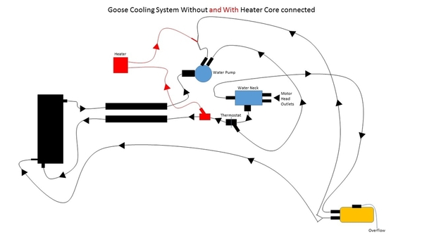
Have gone thru the various versions of Goose cooling diagrams on the forum, and have come up with the attached cooling system without and with the heater connected (right now its disconnected). Does this look about right?

Thanx
Mark

Coolant

Attachments

Images (1)
  • Coolant
Last edited by George P
Original Post

Replies sorted oldest to newest

On your headers, I once saw a CA goose with 'boat-zoomies'- std headers installed upside-down that fixed the a-arm clearance problem, while making the engine harder to work on. Steve Liebenow found the heater valves were not connected on his '69. A Boss 302 is a real mess to install in a Mangusta but a factory EFI non-Boss 302 fits exceptionally well.
Thanx for inputs. Didn't draw motor on chart. Water pump flow out is into block. My weber intake has only the two main water outlets. In my case, the water neck component is separate from the intake but functions the same as if it was connected.

Wondered about 'vent hose' flow, but all the drawings I looked at showed the flow the same making me think it's not a vent hose.

Mark
REGARDING YOUR HEADERS.
When my engine was redone the builders wanted to use 22/4 inch headers pipes to the mufflers. We built a beautiful set of headers that instead of going down and through the rear suspension like the original went up.

The tubes come off the heads and go up and back to a collector, over the top link of the hub carrier and then turn straight down, they turn again to the back of the car and straight in to the mufflers. It works great as there is no exhaust heat near the starter or motor mounts.

The gave me the large header pipe and no interference with the rear suspension. My headers are equal length tubes and very efficient. I have never had any trouble with them, they are jet coated silver.

DICK RUZZIN
quote:
Originally posted by Dick Ruzzin:
REGARDING YOUR HEADERS.
When my engine was redone the builders wanted to use 22/4 inch headers pipes to the mufflers. We built a beautiful set of headers that instead of going down and through the rear suspension like the original went up.

The tubes come off the heads and go up and back to a collector, over the top link of the hub carrier and then turn straight down, they turn again to the back of the car and straight in to the mufflers. It works great as there is no exhaust heat near the starter or motor mounts.

The gave me the large header pipe and no interference with the rear suspension. My headers are equal length tubes and very efficient. I have never had any trouble with them, they are jet coated silver.
DICK RUZZIN


We want to see pictures... Sounds like an interesting setup.
Motor/ZF ready to pull.
- So I don't have to go thru the syncing gears/linkage/turnbuckle drill during reinstall, does anyone see a problem with drilling out the pin on shaft from ZF that connects with linkage and just replacing with SS nut/bolt? I did this on a Bora 10 years ago and its worked fine.
- Went thru the forum to determine best way - both together or separate (the way I did this a few years ago). For separate, does the bell housing come out with the ZF or does it stay with motor? For separate, looks like a clearance issue at the back of he ZF with the frame. Do you jack up motor to angle ZF for clearance of frame?

Other
- How do you remove wipers?
- Assume you remove wiper motor and window sprayer from inside the dash. Is this Right?
- Assume you remove Ghia emblems from sides by going in thru door in each wheel well. Sound right?

Thanx
Mark
I'd try real hard to remove but NOT drill the pin out, as the ZF shaft is high-carbon steel that easily air-hardens with even slightly used drills. Then you will be into beating the remains out with a hammer & punch or using expensive, fragile carbide drill bits while still laying on your back underneath.

Once the pin is out, an aircraft-grade 8 bolt & nut will work fine and be easily removable. But what normally happens is, the mild steel clevis ears of the connecting shaft elongate, introducing slop. Bushing the clevis holes while leaving the short ZF shaft alone, works best.
quote:
How do you remove wipers?- Assume you remove wiper motor and window sprayer from inside the dash. Is this Right?- Assume you remove Ghia emblems from sides by going in thru door in each wheel well. Sound right?


Hi Mark, sounds like your project is moving along. I agree w/ Jack the gear linkage is a pain to work on, the positioning is all terrible!! That said on my car the pins were roll pins and the rear one (which I think you are referring to) comes in/out with relative ease. The one further ahead, near the joint in the shaft and near the engine mount, is MUCH worse to deal with. IIRC the shaft assembly can be disconnected by removing the rear pin only, assuming it cooperates.

Re the wipers and sprayer it's all under the dash as you mention, should not be a problem. As for the badges they are actually ahead of the shields located behind either front wheel so you don't need to remove anything to get access.
Thanx Nate, roll pin popped right out and ZF removed; that will save a lot of anguish getting everything in sync again on the other end; motor removal today.

Dick, have some 351C headers that will fit Boss motor ... already had cut flanges from pipes; once motor is out and while car be repainted, will try to fit/cut/weld them so they exit up over suspension as you described ... just isn't enough room on either side thru frame/support to install headers going down.

A few questions,
1) how are the stainless steel wiper blades removed to get to nut that allows complete removal from under dash ... doesn't appear to be a small screw on wiper hub, but I do see a pin where the blade meets the wiper hub?
2) with front bonnet wide open and disassembled, what are key areas to refurb up front (already implemented the dual electric fan fix with spal fans a few years ago)?
3) both wheel/tires up front appear to tow out ... can a std wheel/brake/alignment shop work on the Mangusta front end?
3) radiator is removed ... didn't leak; should it be cleaned and if so, what is the best best method?

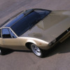
When car was painted red in 1971-72, they neglected to paint under the pad on the inside of the front trunk lid. So, original color is loud and clear and it appears to be a gold metallic(very similar to prototype - see picture). Any one know what this color is?

Thanx
Mark

Attachments

Images (1)
  • dtrmangprotob
Mark,

re the cooling diagram, I can only say that it looks too complicated. I'm also not a Weber expert.

I would hook it up exactly like a 69 Mustang with webers. Excepting the "Y" pipe at the front of the engine that the Goose uses from T-stat outlet down to pipe to up front (hot water out). Also, the one small connection at the bottom of the radiator is different.

All the rest of the connections could be made as if it were a simple Ford. That is what I boiled my drawings down to...while comparing to a very original car with water valves...and then there was my car with nothing left of the valves, and no crossover between the two heater core hoses, BEFORE the shut off valves that I installed in the cabin for emergency and ease of activating heater! Yes, it gets used in my car!

ZF comes out while tipping engine forward...loosen everything that would allow you to do this...take off dist cap....

While engine is tilted forward, you can take off front jackshaft pulley. This makes pulling engine easier.

Then take off starter, bellhousing, flywheel, and block plate. This really makes pulling engine much easier!

Steve
MARK

1.
The wiper ARMS are removed by depressing a small stainless tab toward the center of the shaft and then pulling the hub straight up in alignment with the center of the shaft.
It is hard to see, I think it is facing in the direction of the blade. Look very closely to find it. Once the little is depressed you can wiggle the base of the arm, pull gently and it will come off. Do not pull it without depressing the lock first.

2.
Up front seal everything so that ALL air entering the front of the car has to go through the radiator. At the top of the radiator before putting the top panel on use foam to block off all spaces so that air cannot go over the radiator and then behind it. See the article on Mangusta International for details.

3.
Try to find a shop that has a computer alignment machine with two towers as described in the article on MangustaInternational.com. They have to align the rear wheels first and then the front. A good technician will know what to do. Show them the description described above.

4.Your gold paint may not be like the paint on the prototype. The prototype was a different car altogether although it looked to most people like the later production version of the Mangusta. You might be able to get a color content reading at a paint supply with a computer if there is enough surface to measure.

DICK RUZZIN

Add Reply

Post
×
×
×
×
Link copied to your clipboard.
×