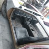
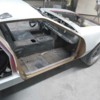
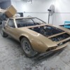
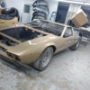
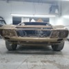
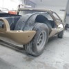
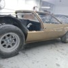
Switched to this thread from previous "Production Data" thread.
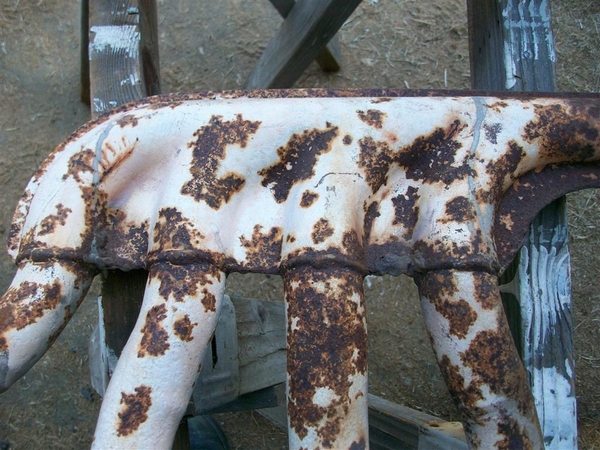
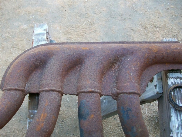
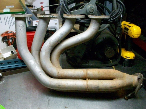
The plan is to refurb both the exterior and the motor of 69 Goose 8MA642 (wouldn't call it a restoration). Will include pulling majority of components and have them cleaned/hot tanked/painted/chromed/etc or replaced if necessary, and replacing cam/lifters/pushrods to better accommodate Boss 302 with IDA Webers performance. Headers may be a bridge too far since the frame mod for the motor leaves very little room to route headers (unless I come up ala GT40). All the shortys and huggers I've seen on line are just to big.
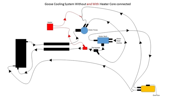
Have gone thru the various versions of Goose cooling diagrams on the forum, and have come up with the attached cooling system without and with the heater connected (right now its disconnected). Does this look about right?
Thanx
Mark
Replies sorted oldest to newest
I do think the flow from the radiator vent would be towards the yellow tank (fill tank ?)
Wondered about 'vent hose' flow, but all the drawings I looked at showed the flow the same making me think it's not a vent hose.
Mark
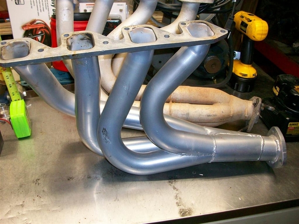
When my engine was redone the builders wanted to use 22/4 inch headers pipes to the mufflers. We built a beautiful set of headers that instead of going down and through the rear suspension like the original went up.
The tubes come off the heads and go up and back to a collector, over the top link of the hub carrier and then turn straight down, they turn again to the back of the car and straight in to the mufflers. It works great as there is no exhaust heat near the starter or motor mounts.
The gave me the large header pipe and no interference with the rear suspension. My headers are equal length tubes and very efficient. I have never had any trouble with them, they are jet coated silver.
DICK RUZZIN
quote:Originally posted by Dick Ruzzin:
REGARDING YOUR HEADERS.
When my engine was redone the builders wanted to use 22/4 inch headers pipes to the mufflers. We built a beautiful set of headers that instead of going down and through the rear suspension like the original went up.
The tubes come off the heads and go up and back to a collector, over the top link of the hub carrier and then turn straight down, they turn again to the back of the car and straight in to the mufflers. It works great as there is no exhaust heat near the starter or motor mounts.
The gave me the large header pipe and no interference with the rear suspension. My headers are equal length tubes and very efficient. I have never had any trouble with them, they are jet coated silver.
DICK RUZZIN
We want to see pictures... Sounds like an interesting setup.
- So I don't have to go thru the syncing gears/linkage/turnbuckle drill during reinstall, does anyone see a problem with drilling out the pin on shaft from ZF that connects with linkage and just replacing with SS nut/bolt? I did this on a Bora 10 years ago and its worked fine.
- Went thru the forum to determine best way - both together or separate (the way I did this a few years ago). For separate, does the bell housing come out with the ZF or does it stay with motor? For separate, looks like a clearance issue at the back of he ZF with the frame. Do you jack up motor to angle ZF for clearance of frame?
Other
- How do you remove wipers?
- Assume you remove wiper motor and window sprayer from inside the dash. Is this Right?
- Assume you remove Ghia emblems from sides by going in thru door in each wheel well. Sound right?
Thanx
Mark
Once the pin is out, an aircraft-grade 8 bolt & nut will work fine and be easily removable. But what normally happens is, the mild steel clevis ears of the connecting shaft elongate, introducing slop. Bushing the clevis holes while leaving the short ZF shaft alone, works best.
quote:How do you remove wipers?- Assume you remove wiper motor and window sprayer from inside the dash. Is this Right?- Assume you remove Ghia emblems from sides by going in thru door in each wheel well. Sound right?
Hi Mark, sounds like your project is moving along. I agree w/ Jack the gear linkage is a pain to work on, the positioning is all terrible!! That said on my car the pins were roll pins and the rear one (which I think you are referring to) comes in/out with relative ease. The one further ahead, near the joint in the shaft and near the engine mount, is MUCH worse to deal with. IIRC the shaft assembly can be disconnected by removing the rear pin only, assuming it cooperates.
Re the wipers and sprayer it's all under the dash as you mention, should not be a problem. As for the badges they are actually ahead of the shields located behind either front wheel so you don't need to remove anything to get access.
Dick, have some 351C headers that will fit Boss motor ... already had cut flanges from pipes; once motor is out and while car be repainted, will try to fit/cut/weld them so they exit up over suspension as you described ... just isn't enough room on either side thru frame/support to install headers going down.
A few questions,
1) how are the stainless steel wiper blades removed to get to nut that allows complete removal from under dash ... doesn't appear to be a small screw on wiper hub, but I do see a pin where the blade meets the wiper hub?
2) with front bonnet wide open and disassembled, what are key areas to refurb up front (already implemented the dual electric fan fix with spal fans a few years ago)?
3) both wheel/tires up front appear to tow out ... can a std wheel/brake/alignment shop work on the Mangusta front end?
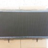
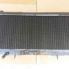
3) radiator is removed ... didn't leak; should it be cleaned and if so, what is the best best method?
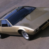
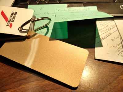
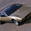
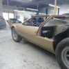
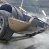
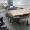
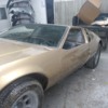
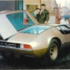
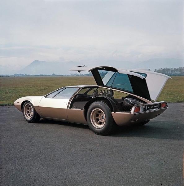
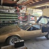
When car was painted red in 1971-72, they neglected to paint under the pad on the inside of the front trunk lid. So, original color is loud and clear and it appears to be a gold metallic(very similar to prototype - see picture). Any one know what this color is?
Thanx
Mark
Attachments
Will tackle pulling windows from doors today.
Very nice.
re the cooling diagram, I can only say that it looks too complicated. I'm also not a Weber expert.
I would hook it up exactly like a 69 Mustang with webers. Excepting the "Y" pipe at the front of the engine that the Goose uses from T-stat outlet down to pipe to up front (hot water out). Also, the one small connection at the bottom of the radiator is different.
All the rest of the connections could be made as if it were a simple Ford. That is what I boiled my drawings down to...while comparing to a very original car with water valves...and then there was my car with nothing left of the valves, and no crossover between the two heater core hoses, BEFORE the shut off valves that I installed in the cabin for emergency and ease of activating heater! Yes, it gets used in my car!
ZF comes out while tipping engine forward...loosen everything that would allow you to do this...take off dist cap....
While engine is tilted forward, you can take off front jackshaft pulley. This makes pulling engine easier.
Then take off starter, bellhousing, flywheel, and block plate. This really makes pulling engine much easier!
Steve
Thanx
Mark
1.
The wiper ARMS are removed by depressing a small stainless tab toward the center of the shaft and then pulling the hub straight up in alignment with the center of the shaft.
It is hard to see, I think it is facing in the direction of the blade. Look very closely to find it. Once the little is depressed you can wiggle the base of the arm, pull gently and it will come off. Do not pull it without depressing the lock first.
2.
Up front seal everything so that ALL air entering the front of the car has to go through the radiator. At the top of the radiator before putting the top panel on use foam to block off all spaces so that air cannot go over the radiator and then behind it. See the article on Mangusta International for details.
3.
Try to find a shop that has a computer alignment machine with two towers as described in the article on MangustaInternational.com. They have to align the rear wheels first and then the front. A good technician will know what to do. Show them the description described above.
4.Your gold paint may not be like the paint on the prototype. The prototype was a different car altogether although it looked to most people like the later production version of the Mangusta. You might be able to get a color content reading at a paint supply with a computer if there is enough surface to measure.
DICK RUZZIN
Appreciate all the advise.
Thanx
Mark
Attachments
I suggest an adjustable, brake proportioning valve to be installed in the front brake T. They make them now to include the stop light switch.
A huge safety improvement.
Dick Ruzzin
That car is "numero uno"!
Factory museum car, originally a push car...later converted to an operational car!
My DNA is in that car....
Steve
Dick Ruzzin
Mike
- status while in car was no leaks
- from what material is original goose radiator constructed
- with radiator removed from car, what is best approach to cleaning it
- for storing over the next three-to four months, should I fill with 50/50 mix to prevent corrosion
- any ideas would be appreciated
Thanx
Mark
I didn't get the original radiator with my car, but these were built by the same company that built radiators for Fiats, or so I was told, and our old Fiat had a brass radiator.
Most that still have them, are happy with them as far as cooling goes! Providing you get cool air into the motor to begin with...!
I would drain it, rinse it out, and just let it air dry. In TX that shouldn't be much of an issue.
If you are going to have it serviced, ie professionally cleaned, a shop will server you best here as they'll have a large tank to dunk it in...save you a lot of PITA work! Have them flow test it first. If it flows fine...it doesn't need much cleaning!
Cheers! That gold is going to look nice! Can't wait to see more pic's!
Steve
You just really don't want to guess whether the radiator is cooling as it should...just too easy to have a radiator looked at professionally. Especially for a 45 year old Italian car...Lee
I am starting repainting my Mangusta 8MA1242 bought 3 years ago. It is painted red, but, as it often turns out, when peeling off that paint, the original color appeared : dark (slightly metallized) blue.
Problem is, in Denis C post from June 27,2011,this color is not mentioned. However, 8MA1242 is a late car, and, according to Pantera International, the official colour catalog of the early Panteras features a "Bleu sera met. n°033.8.012" from Glidden (Industria Smalti e Vernici, Milano).
Would anyone know if that colour was also used on Mangustas ?
Thank you for your advice.
Jean
Thanx
Mark
I'd say it's $600 of one or $600 of the other....!!!
The originals are alleged to be fantastic radiators.......
I put a new aluminum one in ONLY because my original was long gone and mounts were already modified (not to great standards..), not to mention all the fan stuff was cobbled together too.....so it wasn't like I was "changing" anything from stock.
I would like to see the original style maintained if possible. But that's me.
If they can get you the same style of core, with all the fins etc, that would be great!!!!
Fans could probably use help however. At very least, take originals out, lube the bronze bearings with oil, and seal up any air leaks around the radiator so air doesn't bypass it!
(thanks Dick!!!)
Steve
Thanx for you help
Mark
It is a great question, and one that is really hard to answer, since everyone has a opinon on the topic.
If you were going to show the goose at AACA, they would say you have to match the orginal design. As for any other car show, I am guessing they will not be able to tell you that it was not orginal unless the design looks too modern. With the price of gooses going into the upper limit, I am guessing originality will count for something. But as I learned years ago, deTomaso was never about originality.
A couple of years ago, I was talking to my aunt about the idea of an Orginal Pantera. She said that when they had a "reunion" a couple of years after the Pantera was launched, people asked to be judged. Bertocci(not sure of the spelling) was asked to do the judging. He took points off for everything that he believed was not original. She said that in the end, he said only a Pantera that was pushed into the event would have been original. The net net is, do what you want, but if you want to drive it, I would have the best radiator you can find, as nothing is worse than an over heating car.
20% increase but look old!!!
Steve
Denis
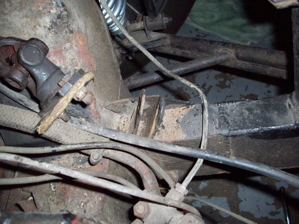
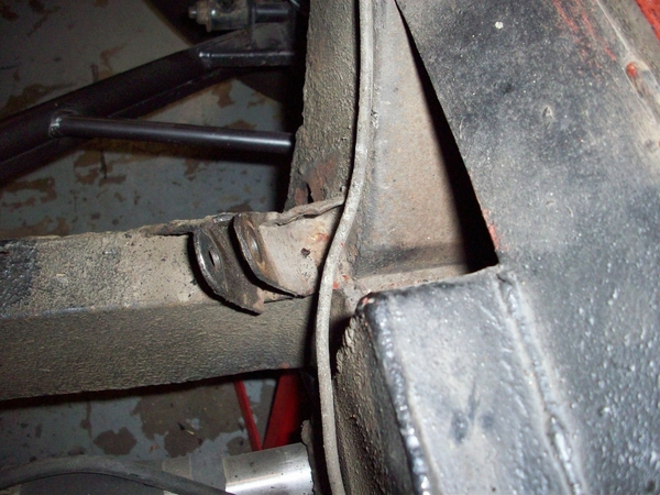
If this is no big deal (ie, not being a structural engineer, I have no idea if this is actually a frame integrity issue), I won't worry about it. I will just clean up frame and POR-15 it to prevent rust.
However, if need be, I can craft 4 appropriately sized pieces steel and weld them around all four sides of the damaged area.
Thoughts?
Thanx
Mark
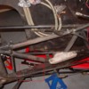
NOTE: this pic shows pretty well how the frame was modified at some point to accommodate the Boss 302 motor.
Attachments
If I still had one, I'd use a 7" (or 5-3/4") double-disc race clutch, a matching small OD flywheel, a reversed starter and trim the bottom of the bellhousing off. One could gain about 3" of badly needed extra ground clearance for maybe $3000.
Interestingly, they said they had to scrap the first core they made because as they installed it, they realized that this radiator had directly flow through separate baffles on the top and bottom. Said Ferrari had also tried this (probably same radiator company!) in the 60's.
Attachments
So what did you end up with in terms of fluid flow? Are these tanks open end to end now vs having baffles to redirect (twice thru???) ??
What are "directly flow thru separate baffles"?
Was it like the failed Pantera "double flow" radiators that are so scorned today?
Very nice job!!!
Steve
(Has no original radiator to play with..
I didn't see the inside of the tank so I can't confirm the configuration, and am not familiar with Pantera radiator.
Hopefully the staggered tubes and louvered pins will make this goose run a little cooler.
Mark
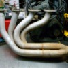
Motor top end rebuilt and have decided to build headers to accommodate Boss motor and rear chassis frame. Shortees and normal long pre-fab headers, whether right side up or upside down, just won't fit.
Mufflers are original and tips need to be re-welded to drivers side muffler. Got me thinking, has anyone installed more modern muffler and retained original look? If so, what mufflers have been used? Boss motor will have IDA webers and 1 3/4 OD headers so would like mufflers to not inhibit carb/motor/header combination.
Thanx
quote:Originally posted by Dan Mershon:
I'd love to see some restoration pics of any kind. I've got a goose also. Not sure I'm ready to go down that path,love to see any pics at all of it apart. Dan Mershon 937 605 1505. dan@mershons.com. Thanks
Dan , I send you a PM whit pictures.
Simon
I need to address a couple of issues when I get it back (should have done before repaint). Any help or documentation would be greatly appreciated:
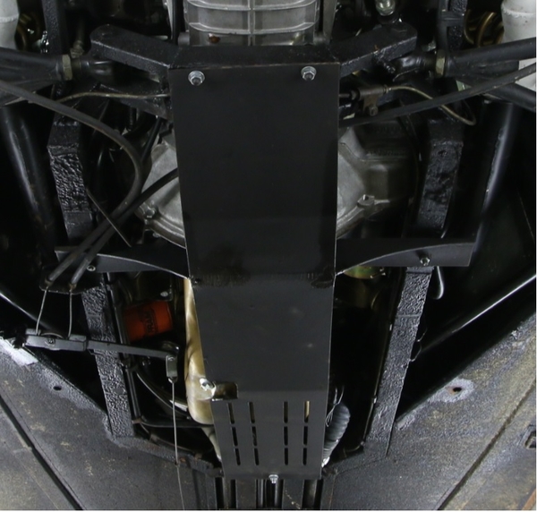
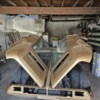
- At some point, someone tightened skid plate bolts on lower frame to tight and caused them to 'in dent' top of frame (see box in attached pic). Is this something that must be addressed? And, if so, how best to do it? I have welding capability.
- Steering is very loose/a lot of play, front wheels each appear toed out, and all the rubber steering rack and other boots are torn and need replacement. (have read various posts on this topic to include Johnny Woods detailed post)
Attachments
IMHO, a skid plate is worth adding to any Mangusta that's driven on city streets. I have an empty Mangusta diff case in my shop that was the victim of snagging a high-mounted manhole cover in a suburban U.S. street. A 'Goose snagged it at speed and ripped the bottom of the bellhousing and ZF diff-case completely out of the car! LOTS of expensive TIG-welding pieced it together like a metal jigsaw puzzle. The outside looks stock; the inside- wow!
I was so in awe of the car....that I FAILED to bend down and look at the stupid skid plate...!!!! Left 2 or 3 rolls of unused film in the rental car also... duh! Boy, what I would have taken pictures of today if I knew what I know...... IT was and probably still is a VERY nice car, but is suffered from one thing.....lack of use! All of the interior had sort of a fuzz growing on it....where if fingers had been involved...probably wouldn't have been there! It was kept in a climate controlled garage with CAV002 GT40, two 67 Vettes (his and hers of course!) and a Jag XKE that was in progress.
My car seemed to have a few extra holes in the cross member.....that looked sort of caved in also!
What people fail to realize is that these motors were regular old 68 Mustang 302's....and those oil pans were fairly restricted to their use in 68 and 69 from what I know. Many of the 302 oil pans sold as proper....are only the substitute part when you order one from the dealership...or from the aftermarket....(which year pan did they copy????)
The 68 pan from what I recall of crashed and dented lower engine photos, shows a drop in the center front of the sump where the drain plug went. Most later ones have a side dump....and may vary in depth again, because of revisions made and then shown as "backwards compatible" to 1964 or so....!
The stock pans were about even with the bottom of the bellhousing when installed in a Mustang. Check out the next 68 or 69 when you see it at a car show....or around....
I don't like the idea of anything "oil retaining" hanging below the frame rails, especially at the front of the engine..a tapered pan with rear pickup would be good...once your wheels start over a bump, the car rises clearing speed bumps and driveways! Different story for big rocks! ....have heard tales of owners backing out of their driveways and loosening the drain plug...! Bad bad thing!
IF you have a mangled one...they can have the dents worked out with body tools..the pan is pretty danged thick material! Weld up cracks...file it all down. I even saw inserts in the Fastenal or MSC catalog for the threaded portion that the drain plug screws into....the inserts were spot welded into the pans in three spots I believe. Any leakage around this insert was stopped by the nylon gasket on the drain plug. The stock drain plugs were a large headed thing....7/8" or 15/16 or so.....
SOOOO if you really want to be proper and correct, you need to rob a pan from your neighbor's garden variety small block Mustang and give him a "brand new NOS" pan......yuck yuck hah hah! Wouldn't be the first time....
The oil pans are also date coded! Some have a part number stamped in them....but that could be just for special pans like Boss 302's etc.
There are some other posts about skid plates....some rather long...... but who knows how many variations of this were made......
Glad to hear you are "almost" out of body shop jail!!!!
Steve
PS: Note that in the above picture, that the upper frame rail and supports have been changed by a previous owner to accommodate a not stock engine and some REALLY bastardized exhaust manifolds! ...could have built some nice headers.....!
Attachments
Modded frame accommodates 69 Boss 302 with IDA webers, jackshaft removed, and A/C disconnected. Previous owners have told me this frame mod dates back to 69-70 timeframe.
Steve, you are correct, car has a "frankenmanifold" on pass side and OEM manifold on drv side. Since I'm not in a rush (obviously), have all the equipment necessary to build a set of headers that work there way around that mod'd frame. Once motor is back in car will build the headers inch by inch.
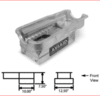
Here is a link to their page on the pan, and here is a picture of it.
The pan is designed to alleviate the clearance issue. I don't have a 'goose so I can't guaranty anything, just that they do make a pan.
http://aviaid.com/shopsite_sc/..._oilpns_sbf-ss3.html
I suppose that you may have a perspective of wanting originality BUT if that is your intent, I think you are going to have ALL of the original oversights?
I would speculate that the value of a Mangusta in the future is going to be to a knowledgeable buyer? If that was me, I'd want the oil pan clearance issue solved?
I believe this pan is 1" shallower like what Shelby did with the 289 in the "Cobra Daytonna Coupes"?
It IS NOT a T pan. The illustration of the pan is not correct. Look at the picture of it.
Attachments
DICK RUZZIN
Attachments
I revise my statement about the oil drain plug....it was toward the side....!!!
I think you guys have the right pans....!!!
Mark: YOU NEED NEW REAR SPRINGS/SHOCKS YESTERDAY!!!
My bellhousing was ground down so far that the bolt holes had no bottom....the holes were reduced to about a 235 degree hole....the rest is out on the roads of CA somewhere!!!!
Steve
I had Armondo build me a 6"ish deep pan, full length, fully baffled, holds 6 qts. I wouldn't call it a racing pan because of the small capacity....but it IS a confidence builder/pucker factor reducer....as I know I will NOT be scraping this mother!!!! Now, the bellhousing still hanging down there is a different story!!!!
Steve
quote:Originally posted by Mangusta:
Mark: YOU NEED NEW REAR SPRINGS/SHOCKS YESTERDAY!!!

Steve
Well yes, but not for that reason. My Mangusta sat so high I could almost drive my GT40 under it. The shocks were fine but I will replace them because I want the car to sit much lower. And, yes, I WILL be fitting a skid plate!
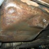
...Mark, here is a picture of the most perfect original pan yet
Nice job!!! Yes that is the correct drain plug!
I cannot say that I have seen that particular way to set the timing. That pointer in that location...... Seems like there are many different/similar solutions so that console center cover need not be disturbed!!!
Did the balancer get remarked or do you take the timing off of a different cylinder??
Lookin' good!!!
Mark, if that bellhousing is from your car....you need new shocks..or your springs are too soft...or both...no matter what the ride height! (Stock DeCarbon shocks or changed...?)
Scraping the bellhousing is caused by either a SERIOUS crown in the road....or serious ass dragging by the suspension allowing the car to sink too low.....there should be travel limiters installed in the shocks....and the springs and shock damping should reduce the excess movement but for the worst of worse cases....then you are on the limiters in the shock to protect you! Perhaps that is why my bellhousing looked so.....similar!
Cheers!
Steve
Searching the web, looks like Hall Pantera has a wiring diagram for 20 bucks, has anyone bought it? Is it any good?
.....obviously early....as none of the Carello relays adjacent to the fuse panel are shown!
But that aside....it is somewhat functional at least in Italian as "a suggestion"!
Steve
It is good to see these De Tomaso books coming out.
Have you seen my book, BELLA MANGUSTA?
Dick Ruzzin
Steve, just to finish on skid plate...Our friend '696 (the gold car in Miami...really does seem to be a nice car) has a clear pic on skid plate mounting...I think I've seen others make this notch for the drain plug.
Nate, for me the hardest thing about the Schematic was dealing with the "2 halves" (where one page has a displaced gap with the other). Good news, the car is simple enough.
Dick, yeah, our family has 2 copies of Bella ![]()
Lee
Attachments
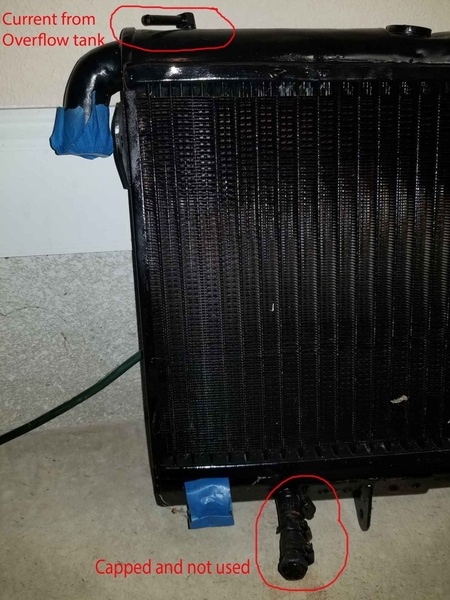
Am prepping for engine stand run of rebuilt motor and plan to use rebuilt radiator to test it. The picture shows a port at the top circled in red that was connected to the overflow tank in the engine bay since I've had the car
The bottom red circled port has been blocked off since I've had the car.
What is the correct connections for the coolant going into the radiator other than the main coolant input coming in from the thermostat housing? Should I be running the hose from the overflow tank to the top port (way the car has been for years) on the radiator, or the bottom port (blocked off for years) on the radiator?
Thanx
Mark
Attachments
I ran the top connection on my expansion tank to the small connection on the front "Y" Pipe off of the thermostat housing.
The lower expansion tank connection went up to my small connection on the radiator, where-ever it was..... I believe it was at the bottom....
My diagram I posted showed originally the lower connection on the expansion tank tied into the crazy hoses that were the heater shut-off valve circuits. I believe you said that you weren't running a heater???
For testing just connect the main large connections and don't worry about the small stuff. Connect it like it was in a regular Ford! Keep the radiator high enuf to be the "top tank" in a normal car, and just watch the water via the radiator cap there! Keep it simple!!!!
Make some noise!!!!!
Steve
Alright! Progress!!!!
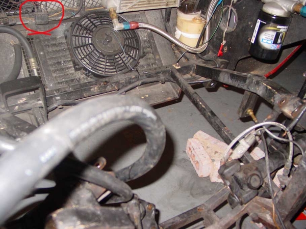
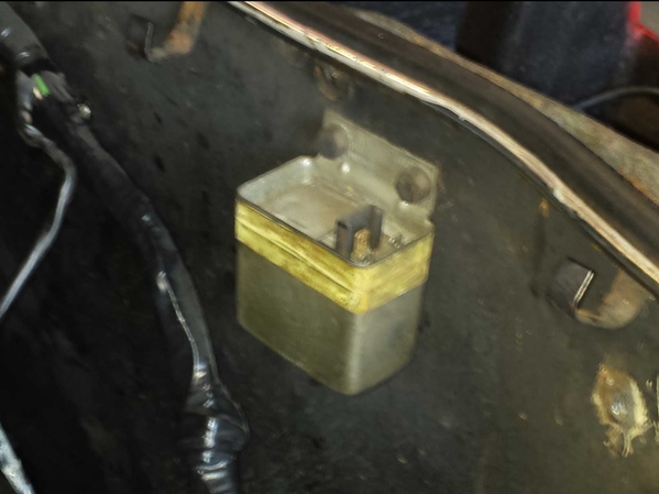
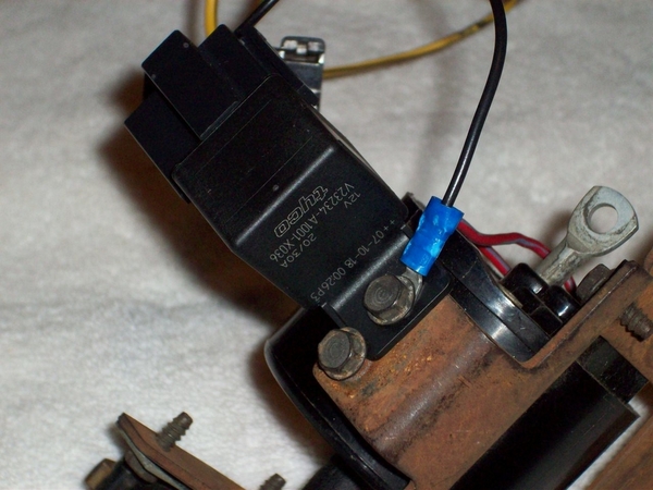
Re the relay above the AC condenser fan.....while the connectors from afar appear to perhaps be original style, I have no idea what it is for....unless it is for lights or the fan.
Follow the wires.
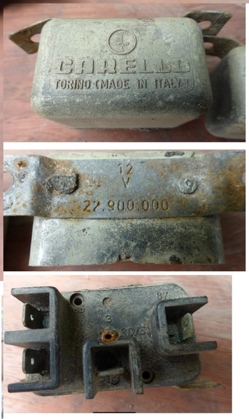
As for relays on factory wiring diag's, they are notably missing from copies that I have and what I have heard from others...... The two above/adjacent to the fuse panel are for AC, stuff under the dash..... and radiator fans if memory serves me. Carello....plastic housings....tend to "soften" with heat....!!! Keep some Bosch "relays on a tab" handy.... Don't forget to assure that your ground connector(s) to these relays are making good contact.....thru thick insulation!
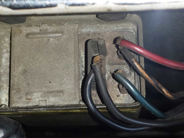
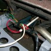
Ok, second relay....if this is on RH wall of engine compartment, I would bet that this is a voltage regulator of sorts.
Get numbers off of the cases of both....and you can likely find new replacements! The regulator came in two sizes....20A and 30A or 30-40.....and were paired with the Bosch alternator size....(current).....
These voltage reg's showed up on VW's and others...... IF that is what is is.
Mine was mounted wiring connectors down.....opposite of yours.......
Gobble gobble!!!!
Steve
Mark, the relay in the back isn't original; the voltage regulator (2nd [pic) was used on Mercedes and Porsche 914, check Bosch #30-051 or 0 190 601 006 (I have no idea if these are 20A or otherwise as Steve mentions). These are available as aftermarket, and probably won't take too long even to find NOS.
The fan relays Steve mentions were Carello, 22.900.000 . I haven't been able to find these anywhere...Lee
Attachments
If you burn up one of these Carello units, the BOSCH "block" relays work fine. Best is the ones with the mounting tab on them. They come in two flavors, 30 and 40amp. 30's should be sufficient for these cars, excepting some aftermarket fans!
Steve
Once I get car back from paint, I'll some sleuthing to figure what rear relay might be. Right now, am just building engine test stand wiring so that rear relay isn't a player.
Fan wise, I replaced my radiator fans with two 1500 cfm Zirgo's and used a couple of Bosch relays.
Mark
quote:Originally posted by LeeA:
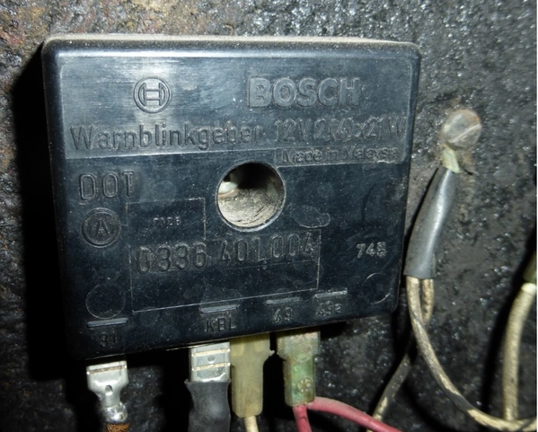
(Just adding a pic of the Bosch relay Steve mentions, must have been Hall that provided these ~30 years ago...!)--Lee
Thats a turn indicater relais ,this is not what Steve mentions.
Simon
This is one of the cube relays..... in a completely different application....but you can see the mounting tab! There is a socket installed on this one.....which could be potentially used in the Goose, but not necessary.....unless all of your connectors are toast and need replacing anyway!
Attachments
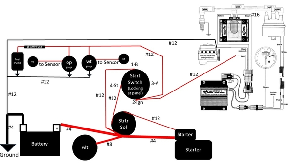
For you folks that are electrical gurus, how does this wiring set up look for a test stand to run Goose engine? The starter, starter solenoid, alternator, battery, oil press sensor, water temp sensor, and ignition system are the components I'll actually install in Goose so thought it would be good idea to test them. I had goose fans/relays/fuses wired in in my first incarnation of this but just decided to put a floor fan in front of radiator when temp gets to 180.
Attachments
I keep a set of manual gauges for oil and water monitoring..... hook up the coil with a paper clip to power....not really.....but a big wire.....jumper cables to the starter solenoid, some gas in a can and hit it!!!! Make some noise!!!
Drawing looks good with only one question about #12 wire to 1-B on ign switch for alt charge. I would think this connection would be to #2 for the "run" or "ign" mode? Not sure what the #1 terminal is here......
As for the Accel stuff and tach......hafta go with what they recommend in their papers.....
Video at 6????
Steve
Thanx much.
There is no real stock mirror on a Goose....many were shipped here without...and dealers popped whatever they had on a fender or door and away it went......
You might post a pic of the mirror you are dealing with...perhaps then help can be offered....
Glad to see progress!!! I bet you are also!
Steve
4263598 -
https://www.ebay.com/itm/RELE-...p2060353.m1438.l2649
I bought "Itab" made relays, which (like the Carello) are also marked "Torino" and I'd bet were a common manufacturer as the Carello. I did buy a NOS Carello 22.900.000 many months ago, it was very expensive but I was drunk with the find...
The Sipea part numbers for this relay (with metal instead of plastic body) seem to be 5170 and 7810.
Good find!!! I would venture that your theory of manufacturer supplying others is probably not far from truth..... That looks too similar!
I found some Carello relays on some Italian car in the junk yard years back, but found that one was a "NO"= contacts "normally open" and one was "NC"= contacts "normally closed".
Some relays, like the small cube Bosch types may have both options are are great substitutes in a jamb or as spares.... But the Carellos seem to be one or the other!
So, buyers beware!!!!
I like the circuit on the plastic to "explain" how to hook it up!!!
Cheers!
Steve
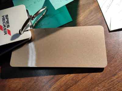
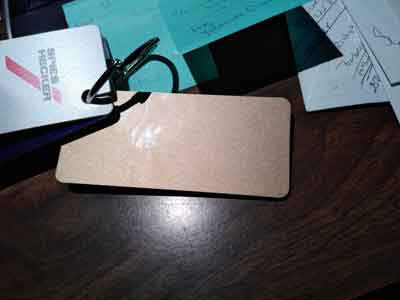
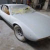
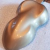
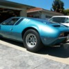
Well, a little movement in the right direction. Almost 4 years since going to paint shop. Car has been red, but original color was copper. New color will be as close as I could get to metallic platinum on the prototype. Attached are samples of the paint selected. Since the prototype's metallic platinum was not one of the original gooses colors, this Porsche color appeared to come the closest.
Attachments
Keep up the good work! A few months ago there was a very original/low mile goose for sale, I believe it was out of Florida. I thought it was the same color as the original prototype, but that was just an assumption. It looked pretty close to your sample chips. Sadly can't locate the ad at the moment.
You know, I remember seeing that car advertised now that you mention it and show the pics. I am guessing that is the color my car was initially (copper). I am really hoping this new color is close to the prototype if not exactly the prototypes color.
Found this on youtube this morning:
https://www.youtube.com/watch?v=5p4JLdDe8SY
The car in this youtube video looks like the folks who restored this car in the 90's were trying to match prototype color as well. This is pretty close to what I'm hoping for.
Goose should be coming back from long paint (in shop since 2015 in the next couple months - I hope!!).
I know I need to rebuild front suspension and steering (as well as rebuilding the rest of the car) . Couldn't find detailed writeups on these items. Anyone have this data?
Thanx
Mark
Others can likely provide better info but here are some off the cuff thoughts;
Inspect front A-Arms for cracks or signs of stress. If they are painted or coated, it may be worth stripping them to reveal the metal. Rear A-arms are known to fail as well.
Make use of the grease fittings to lube up the joints.
Replace shock and spring which can be sourced from PI motorsports. For mine there was some light machining work needed to attach them properly, but nothing major.
Find an alignment shop who is familiar with old Italian cars. Bump steer.
Bushings may be in poor condition. Consider cutting new from Delrin. Actually not certain if Delrin is best for this application but I have found success with it as a bushing material on other cars.
Since it's all apart, you might as well address the rear transmission support. There's a great amount of detail related to that topic on these forums. I won't try to re-hash it here except to say it's important if you'd like the car to handle reasonably.
I know little to nothing about the steering. It sure would be nice if there were a rack with a faster ratio which could be swapped for the slooowww factory rack. One day when the car is more sorted out I'd like to attempt adding an electric power steering 'helper'. They are popular in the offroad world.
Mark, Scifi,
Some observations of mine over the years spent getting our car back on the road....and some efforts of others!
Front A-arms: Your early car likely has "rev-A" lower arms. These have metal strip welded along bottom of tube(s) but stops short of the ball joint cup. This is where they are known for failure...cup busts right off. Rev-B arms used a metal "U" channel about 3/8" or 10mm square which is welded along the bottom at intervals, and extends over the BJ cup area strengthening the whole mess. I had one of each on my car due to accident...welder could only find solid bar to use, but I think "U" style is available if ya look...... (MSC ???)
Front Lower Bushings: Inspect and fab replacements as needed. I put some new ones in.....but they didn't offer much improvement if any, over the old ones! They do need some lube all over everything to prevent squeaks....there are no grease zerks here.....luckily you can just lift the corner of the car to unload the suspension and the two bolts can be removed allowing the lower arm to be dropped for servicing.....doesn't affect any alignment.
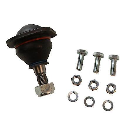
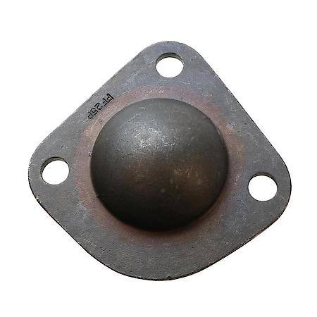
Ball Joints: Inspect for blown apart ball joints. Originals appear to be two pieces of stamped steel welded at the edges. You can expect multiple pieces to fall out if you still have originals. New ones are cast units- Fiat 124 uppers if memory serves me. DO NOT grind the a-arm cups to accept new ones...... get the proper ball joints...! They are out there and readily available.
Rear A-arms are a little more beefy- I had no issues with these.... Often bent from idiots raising car with jacks under arms......!
Trans support: Lots said about this, but only one modification I would accept on these cars, which is to add inboard connections for the ladder bar at the top of the shock towers. (Inboard about 5-4" from outer upper shock bolts.) This will "help" prevent catastrophic failure if the shock tower cracks! Don't ask how I know this...... Easy enuf to do.
The bushings at the outer ends of the trans cross member are the same as the stock shock absorber bushings....if you have any good left in them.....but these bushings usually stand up better in the crossmember position! Not sure of availability any longer....you may need to fab something up!
I added a small stiffener bar between the outer mounts of the trans crossmember to prevent "some" amount of frame flex.... I know that other solutions have been suggested for preventing "Z" flexing of the chassis under hard cornering...it's real.....but quite frankly, it's way easier just not to "hard corner".....! After all, you are driving a 401K plan that has performed handsomely over time....no need to trash it senselessly now! IMHO, if you NEED to go hard cornering, buy a different DeTomaso or a late model 5L car and have at it..... Drive your GOose in a gentile and stately manner around curves! ![]() )) You will look fantastic doing it!!!!
)) You will look fantastic doing it!!!!
Steering rack: While the RHD cars allegedly had a swap rack to drop the ratio, I have not heard of any for the LHD Goose. In my experience, after now driving a Pantera for a while, the Goose rack feels very comfortable compared to the lower ratio in the Pantera. Not ideal for close corner fast-slow speed maneuvering, but since you are carving the corners off of your new tires, and stressing all of your frame member attachments, just don't do it. Your car looks fast sitting still....... The higher ratio rack makes the car easier to control in and out of parking spots!
Bump Steer: Ugh. We have one or two members here with extensive frame/steering knowledge that set out on an effort to cure this issue. The results were either epic failure, or "it fixed some of it". The latter required machining of the outer steering rod on the spindle, spacers for the tie rod ends.....and perhaps a little more. More than most would like to undertake....perhaps. Attempts to raise or lower the rack find interference from the frame in every direction! Wholesale redesign of the front frame members required. Not going there!
I would think that when doing close to triple digits on a bumpy road is where bumpsteer would be an issue...and not on smooth roads. So, stay off of bumpy roads when driving fast! Your chassis will love you for it!! ![]() ))
))
Love the car for it's beauty....forgive it for the defects, and "drive around" the bumps!!
Cheers!
Steve
Thanx Steve and SCIFI
Here were the front end 'symptoms' before I took it into paint...wheels splayed out to some extent when steering wheel in normal position, and lots of play in steering wheel...I could move it back and forth from 10 to 2 and the wheels wouldn't move...almost all the rubber boots in the front end need to be replaced (and I'm sure the bushings are right there with them). Any ideas on what the major problems might be?
Since the chassis has everything removed for the paint job, when I get it back is the time to completely take the suspension and steering apart and rebuild to something acceptable to 'drive like a 401k' (I like that Steve). I'll look for all the items the two of you mentioned. Any gotchas on taking the front end apart?
Also Steve, have my 69 Boss 302 motor rebuilt ready to test run and reinstall into the chassis/frame that had been modified back in 1969 (professional job vs hack job) to accomodate the wider heads and sit low in the engine bay to fit comparable to a 289/302. The OEM drv side exhaust manifold is fine and fits perfectly in the modified frame. The OEM pass side exhaust manifold is a franken-manifold since the exit from the manifold had to be relocated low and between the two middle exhaust ports. My options are: take the franken-manifold and have it refreshed to patch cracks on old welds and redo bolt holes, or try to build a set of headers (options being weaving thru frame low or going high like Dick Ruzzin did in his car). What are your thoughts?
Mark
Mark,
Re the "lots of movement" in the steering wheel..... check condition of ragjoint, the tiny (unobtanium unless in Europe) U-joints, and after that, my guess is that it is all in the rack gears. Rack is simple deal.....only two moving parts! Clean and inspect rack and input gear for wear/play.
Front end is pretty easy to take apart. Upper shock bolts can be fun... Upper a-arm bolts could give you pain if they are corroded in place. Clean and grease before assembly..... Nothing really major....not much to it all. If you unload both sides at once, sway bar connections will come apart more easily. Be careful not to damage threads on outer tie rod ends when taking it apart. Use two hammer method to "compress" the steering arm end, to pop the end joint out of the arm. The parts on the steering rack ends to the tie-rods are specially modified parts in some cases. Not "off the shelf"! (This may not apply to late cars)
Boss 302: ......after fighting with the crummy fitment of the headers with my Boss, the raised motor mounts, air cleaners that wouldn't fit, and more..... namely being the 331 5.0L based SBF engine that I put in place(!).... that engine ran SO much better than the Boss......BUT, the Boss had issues due to mod's meant to "de-perform" it to make it more driveable.....which didn't quite work..... It should have ran and performed better!
As for your "franken-manifold".....tough call! I would have offered you my "franken-headers" from my car, BUT, they were 2V port sized...not the 4V that you have! Is there ANY chance that a 70-73 351-4V right hand manifold might be more easily modified and substituted for your chopped up Boss manifold??? If not, I think I might be inclined to go for a new header....with the ugly being the fact that you're not going to find anything out of the box to fit! Although, that said, you could have some luck perhaps, with a set of Pantera headers to start with! I think I have a couple of sets of original exhaust headers with slightly eroded end flange areas (at muffler end) but the top section may serve as something to start with???? May be easier than a flange and a "box-o-curves" kit that you would likely need!
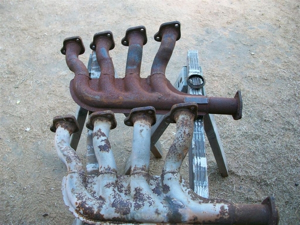
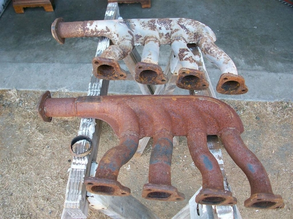
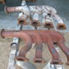
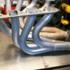
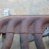
Here are some Pantera headers that I have, some have cracks in all the normal places.....! So good candidates for mod or copy.
Gotta go play plumber...ugh.....!
Attachments
Look, I know I'm being a bud-in-ski here. It seems to me that running a Boss 302 head in a Mangusta isn't worth the effort with the changes you are talking about?
I'm using AFR 1388 heads on my 347 in my 68 GT350. Go and look at the flow numbers on the heads. They out flow stock Boss 302 heads.
They are a direct replacement for the iron 302 J heads once you shave them .024".
That means everything stock Mangusta is going to bolt up to them. You don't need Boss heads. The AFR's are better.
Now if you are going to say the AFR's are modifying the car, what do you call a Boss 302?
OK. Enough of my budding in here. Sorry to interrupt your discussion.
No sweat, am sure you're right. Car had the change made to Boss 302 motor in late 60's. Apparently, it may have been Chicago or Detroit Auto show car (couldn't get this verified). Does kinda make sense since the saying used to be 'race on Sunday sell on Monday'. Anyway, will keep it this way since its been in this configuration since the beginning, and refresh it as close as possible to the way it was in 1969.
For future reference
If you (any member) would like a topic opened, just send me a private message & I'll open it for you.
If there was a universal way to unlock all topics I would, but there are too many to unlock them all one at a time. However I'll gladly unlock them by request.
How exciting!!!! You must be stoked with anticipation!
Well finally a little movement. Attached are the prototype color I am going for and the paint model I received that my Goose will be painted...close but not a perfect match.
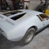
After 5 years, positive movement!! Car was completely primed and ready, but they found a 'reaction' between primer and metal so they are stripping it and putting on a different primer. Shooting for paint in attached color in Jul.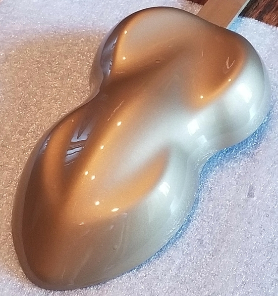
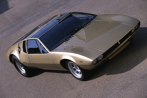
Attachments
great color can i ask what it is
That will be awesome. Keep posting pictures as you can! Everyone wants to see it!
Rocky
Tried to find the prototype color in the De Tomaso pallet of colors to match, but it wasn't there. Went thru Ferrari and Maserati colors as well, but didn't find a match. Eventually, the platinum color selected is from a Porsche 911 from a few years back.
Are you going to match the wheels to the car, like the prototype, or use the Argent Silver?
Wheels already one and match those in the prototype pic I included. Believe they are argent silver.
Great color!.....will be SO nice when everything is done, looking forward to more photos as work progresses![]()
Look at https://www.madle.org/ecolsamp.htm.
I think DeTomaso use Glidden Salchi S.p.A. colors for Mangusta.
Congrats, really nice.
SCHWING!!!!!! How exciting!!!! Been a long road!
Steve
Would appreciate someone providing dimensions of battery location so can purchase new battery for Goose. Thanx.
...I can't think of many cars that would ever look good in gold...but it really works on a Goose ! congrats!
The battery is a Group 24F.
I think it is going to truly take on its true glory when assembled and sporting some bright bits, some blacked out bits, and a complementary interior color palette.
have you chosen a wheel color yet?
Larry
Not to second guess Denisc but you may want to double check the dimensions before buying your battery. Mine had odd protrusions at the very bottom, so even though the overall dimensions made sense the battery would not sit flat in the tray. Relocating battery to front would be a big win for weight distribution. Not only does the weight leave the rear, but is added up front. Then again it looks like you are striving for some sense of originality so maybe save that trick for your next Mangusta.
The Goose battery is a 24 series version. The factory used a rubber pad (from Carello!) to set the battery on, which would lift it about 3/16"......but it would be easier to find a "protrusionless" battery!!!
Edit: 12/19 I miss stated above about the Carello battery "pad".... since the Goose battery tray is not solid flat on the bottom but more like "angle-tin" pieces....with a big hole in the middle.
I found "strips of rubber" that fit into the frame bottoms and on the backside of one of the strips I found "Carello"....... probably didn't take pictures......just put it back in place.....!!! Sorry!
Scifi- you are correct......don't go cutting up the Goose!!! Remember when driving your 401K around......weight distribution isn't an issue!!!!! Neither is cornering...... acceleration.....braking....., OK, you probably should have good braking......
Ciao! ![]()
Thanx for battery data.
Logistics question: Car is completely stripped of everything (including motor and mechanicals) so its pretty light. Have a 4500lb capacity winch attached to front cross bar of 4 post lift to pull goose onboard and will reassemble it on the lift. Not having towed the goose anywhere, what are the best attach structural points up front to wrap around a nylon tow rope forming a triangle shape to be reeled in with the winch? Thanx.
There may be a tow loop on the driver side of the frame rail, near front of car. The trouble is, unless winch is low to ground, using said loop would cause cable to come in contact with front facia, thus the need for a strap in a triangle shape at the front which makes a tow bar so to speak and saves the car from damage. Photo attached. I did not see exactly where the strap went.
Attachments
Hmmm, thought I responded to this post.......must have missed a key.....!!!
You can wrap straps around the lower frame rails up front. They are completely boxed and can handle this massive job. Depending on the lift and pull angles, you may want to put a 2x2 or 4x4 across the rails to keep the strap down off of the front valance.
In the pic, you can see the frame rails and the bracing...where you can sneak straps thru with no fear of slippage..... Please ignore my messy wiring........was trying to duplicate factory job..... ![]()
![]()
![]()
Attachments
Hi Mark, any updates on the project? PM sent! Regards, Nate
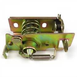
Well after 8 years, a couple different owners, a shop location change, and 3 Presidents, the paint job may be about finished. Looked at car today for pre-delivery inspection, still some things to clean up. Missing are Ghia emblems (no big deal), the forward latch on the drivers side for right rear lid (big deal), the black metal plate covering the vents of the right rear lid (can be made out of sheet metal), and both rear lid windows in front of the vents (big deal - will be have to be specialty made to fit).
Any ideas on the missing items?
The under side cover for the hatch "gills" was aluminium with a drain, but you have one to copy.
No use telling you that I used to have the hatch small windows......! Don't recall where they went.... Try Steve Wilkensen! Ya never know what he may have!
(Do you still have the chrome trim around the small hatch windows? These would be a bugger to do!)
Someone found the hatch latches in the past.....try searching this site! Maybe they'll chime in....
Ghia emblems in repop form are adhesive backed....stick 'em where needed!
Gotta feel good to see the car in color finally!!!!! Sharp color!!!
Cheers!
Steve
Here was as close as I could get to the latches...Lancia Appia, maybe Fulvia. Look on Ebay Italy. And Wilkinson just may have the port glass.
ALMOST GOT LOST on Lee's old post!!! ![]() )))
)))
Saw this below one of the links to a pointy thing auction! May be the same seller......
https://www.ebay.com/itm/255652132921
The above is one of the receptors of the pointy things...
See if cut n paste works....

Didn't seem like the GOose creators got this creative??? ![]()
Do you need the pointy thing for the hatch or the latch portion for the body?
Steve
Thanx for all the ideas. Will check out the various Lancia latches and see if I can find a suitable substitute. I did find a place in the UK that will reproduce the small rear lid windows in Lexan. Still will have to sort out seal and chrome trim.
Lee, in reading the threads, what did you end up using for a latch? Like you mentioned, this looks pretty close...
COMPLETE REAR TAILGATE LOCKING DEVICE (BAF33-0007409 - POS.15)
Complete tailgate locking device for Grecav Eke.
29.63 €
....just as I thought I could jail break out of Covid and go back home, my wife got pregnant and I'm still in Taiwan--I still haven't gotten a chance to see these pieces (that I ship to the car in Houston). But my money is betting on the Lancia Appia or Ardea pins/latch. Yeah, I bought the latch (not needing one, but still so curious if they are the same ![]() ) ...
) ...
To answer Steve's question, I have the male (upper) component of the forward left rear lid latching mechanism.
Lee, will hold off on buying Grecav Eke latch until I hear what you think of the Lancia pieces you have. Let us know what you think of those latches when you see them. By the way, where did you find/buy them?
Sorry for the delay--my suggestion is start with "scontro Perno" on Lancia Appia or Ardea, on Ebay Italy, and work backwards (contact the seller and see if they have a latch). The Grecav Eke may eventually work, but the pin is rounder. Here are a couple shots to take first;
https://www.ebay.it/itm/325746...p;LH_ItemCondition=4
Saw all parts of Goose completely painted and polished in platinum yesterday. Looks pretty good. Shop is reassembling, cleaning/painting engine and side bays, and fabricating and installing some parts lost during the process.
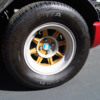
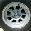
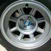
Wheel wise, anyone know if the wheels on prototype were silver, or platinum, or a mix of the two colors? Right now my wheels are silver. Atch 1 is a pic 'Roger' posted a while back of the prototype that shows the wheels platinum. Atch 2 is the way my wheels were when I bought the car with the wheel centers/spokes matching the original color of the car.
Attachments
I wonder (loudly! ![]() ) if the gold insert wasn't an owner change....
) if the gold insert wasn't an owner change....
I have been seeking Ford Argent Wheel paint from VHT, for my new (to me) Pantera rims, and apparently the entire planet has been sucked dry of this version.
On my Goose I went with a BMW powder coating if I recall correctly. There are some Dupont numbers scrawled on the receipt, but it appears that it was a two part thing as one of them is clear....... I do not recall approving a two part.....as I hate two part paints.....trouble trouble trouble!!!
I think mine came out just a tad bright, but all I had to compare to was 15+ year old stripped to bare magnesium wheels.....not even close...!!!! So I just went with the BMW thing. Now, this was back in the early 00's that I had mine done. The coating held up VERY well!!!
Some pic's for you.
Steve
Attachments
MUTTSJET,
Wheels on #596 had gold paint on the spokes. I wish I knew the answers to your question about the finish on the prototype wheels. I'd like to spend the rest of the afternoon researching that but of course, life has other plans.
A cool trick is to finish with a clear coat but use what's called a 'knockdown' clear coat. Keeps things from looking too shiny. I think we used a 25% knockdown.
It gives a special glow to the wheels that's hard to describe. Pleasing to the eye but not distract from the rest of the car.
One more thing; a horror story from the gent who did my wheels-
Lamborghini Diablo has Campagnolo wheels. The shop refinished the wheels, reinstalled them, and torqued the lugs to the proper value. Customer picks up the Diablo and makes it down the street until the first high-speed turn. The front wheel came loose, flew off, and did massive damage to the car. Apparently, (according to the story) it was due to the fact that they refinished the area where the lug lands against the wheel. Either the slick finish or the added millimeters somehow caused the wheel to come loose. So moving forward the guy always leaves a tiny bare space where the lug lands. Not visible once the wheel is installed.
I always sort of suspected someone forgot to torque the wheels and that was the true cause. I mean of course, you're going to blame some exotic thing like refinishing because, with that construction, some of the blame is shirked off to the idea of an exotic and arcane cause. Makes you look a little less stupid than if you simply forgot to tighten the lugs. So potentially it's a BS story but I wanted to share for fun.
I looked at a bunch of cars listed on the PromaMO site. with the exception of a few cars with aftermarket wheels and the red car with gold inserts on the wheels, they all have what appears to be Argent Silver painted wheels identical in color to the Pantera wheel. I dont see anything that looks platinum. If you have an account, check them all out as there must be 250 cars on the site.
I think your picture may have been tinted or something as 001 is in the registry as posts by Mike Drew when seen in Italy and the wheels are just like all the other cars. Hope this helps.
Attachments
Simple answer. The 1st pic is the pusher the second is the driver when they converted the Prototipo to a real car. So both are correct. I have a wheel I acquired with little or no real road use. The color as Steve has mentioned are a Ford /Mazda silver. The wheels were clear coated and that clear has yellowed. Not as bad as the pic but still. I seem to remember a miura with gold wheels as well. That may have been a period thing to do.
What you want to do here is ditch the Boss 302 heads. Go with AFR #1388 heads.
They outflow stock Cleveland and B2 heads by a lot. Right around 300cfm out of the box with a mild .500" lift cam. Try 250's for C and B2 iron heads. They are Windsor style and will bolt up to your 'goose headers.
You will also loose 55 pounds from the engine assembly because they are aluminum and they are a direct replacement for 302 iron heads.
You can mill them up to .020" to play with the combustion chamber cc's. You can easily get them down to 54cc's.
Then you can go with a Cobra style Weber intake which are much more plentiful then B2 Weber intakes. How you deal with the jack shaft I don't know but I have seen Webers on running Mangusta's so it must be doable.
On using a jack shaft with IDA Webers it is possible. You won't be able the run the existing jackshaft, you have to fabricate 2 brackets at each end, its the jackshaft mount not the actual shaft that gets in the way. I can't seem to find a photo of the final set up we had, this are from the early mock up. We put the Webers on when contemplating racing it but found while its sounded awesome we never quite got to grips with (more like we didn't spent enough time to get to) a proper tune for it. Its was more powerful (or at least easier get the power) with the Holley. Torque and throttle response is much better with Webers though. There are a couple of IDA manifolds which are made and some have the carbs angled which I think could provide even more clearance for the jackshaft.
Hopefully the pictures assist.
IIRC we use chrome moly tube as you need to be conscious of Critical Speed and whip, if going full on to full off with the throttle. but again IIRC we only used bearings at each end not in the middle.
Cheers
Larry
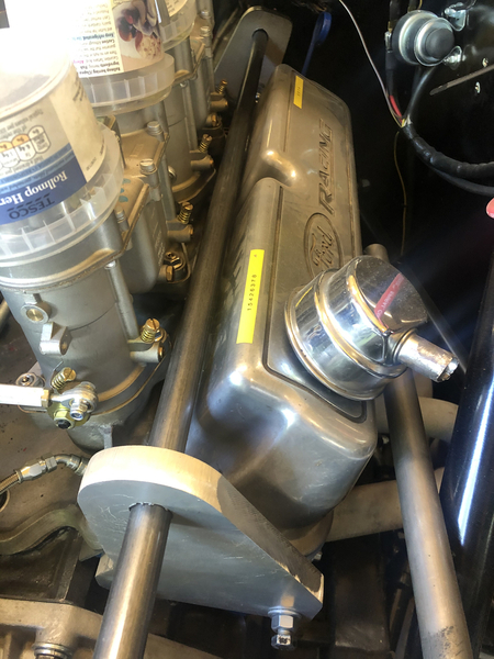
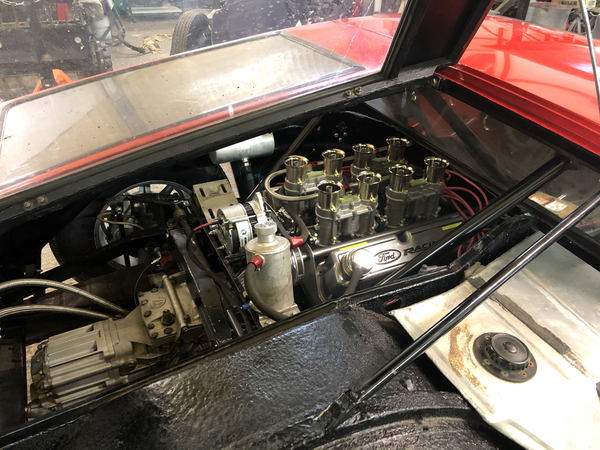
Attachments
@leea posted:....just as I thought I could jail break out of Covid and go back home, my wife got pregnant and I'm still in Taiwan--I still haven't gotten a chance to see these pieces (that I ship to the car in Houston). But my money is betting on the Lancia Appia or Ardea pins/latch. Yeah, I bought the latch (not needing one, but still so curious if they are the same
) ...
Congratulations to you Sir! You might be surprised to read this; but babies can be born outside of Taiwan. No need to remain for that.
OK back on topic sorry for the hi-jack. ![]()
![]()
@scifi posted:Congratulations to you Sir! You might be surprised to read this; but babies can be born outside of Taiwan. No need to remain for that.
OK back on topic sorry for the hi-jack.

...well, the critical thing is that the wife got pregnant while I was in Taiwan... ![]() But I'll be sneaking back for the first time in almost 4 years, one month from now...
But I'll be sneaking back for the first time in almost 4 years, one month from now...
..btw, re: the whipping jackshaft---At least what strikes me is that the original jackshaft housing (as a single piece tied on both ends, and a very short distance between the mounting on the engine and the bearing centers) is different here (where front and rear uprights are independent, with apparently a long distance between mounting bolts and bearing center). Is there any feature necessary to align front to rear?
I can see why 8ma1074 mounted (with just a high rise manifold) their alternator to the front and (in Emeryville CA) sacrificed AC...)
Are the Ghia emblems on the front fenders 38mm tall? Trying to find a couple since they were lost in paint process.
Try sending Johnny woods a note he had a few OE Ghia NOS emblems stashed away a while back.
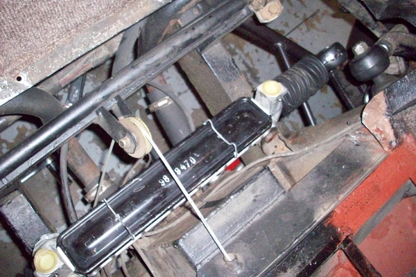
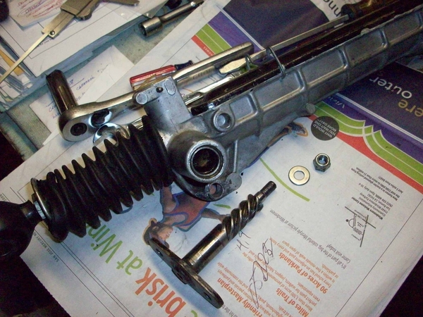
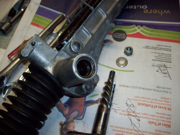
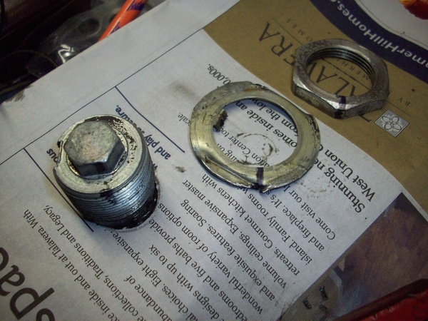
Steering question...does this steering rebuild kit for the Renault 4 rack look good [Steering rack repair full kit for Renault R4 4L from 1979 to end of production. - vehicules-anciens.fr]? What key points should be looked at when going over the disassembled rack to know what is good and bad? Also, should the heim joints and bushings on each end of the rack be replaced? If so, couldn't find the part number and where to order on the forum. Read forum discussion on the u-joint on steering column, but couldn't determine if there are replacement parts available, or if it is a unique part?
Wow, the gold paint looks great...really distinctive, so much remarkable than I had expected.
For the steering rack--who knows?! ![]() The housing itself seems to be a custom thing only for the Goose, but otherwise just suggest aiming a decade earlier on parts (say, for Dauphine)..Likely the stuff starting at 1979 and later mostly works, for some reason I think I bought parts from https://www.franzose.de/en/Renault/R4/steering-gear/ (just to have them, I haven't done the work).
The housing itself seems to be a custom thing only for the Goose, but otherwise just suggest aiming a decade earlier on parts (say, for Dauphine)..Likely the stuff starting at 1979 and later mostly works, for some reason I think I bought parts from https://www.franzose.de/en/Renault/R4/steering-gear/ (just to have them, I haven't done the work).
I had to change the inner tie rod ends/heim joints on mine. I just used the mfg number on them at the bearing shop. Got them in a few days at a reasonable price.
This is an area that I thought had been pretty much determined some time ago with the Dauphine being the winner (donor!). I recall taking my rack apart to see if there was any way to remove any slack in the rack.....and found very little to be able to do!
I think I just greased the Unibal joints, slapped on new rubber booties, packed the whole thing with some new grease and put the cover back on! A pretty hardy box if I may say so!
Here is where it get's dicey. Denis mentioned simply going to the bearing house with his parts in hand and coming home with new parts! While tie rod end may be true (Fiat part according to the parts book...... probably posted elsewhere on this site, but I don't have it handy(!) but in most cars, the Unibal joint was a very custom piece!
The rack center shaft may have been modified (shortened?) when compared to the stock Dauphine parts. I think it was modified to accept threaded Unibal (14? or 16) joints. That would be a MODIFIED Unibal joint where the threaded shaft section was turned down and rethreaded! (Likely why I greased mine and put new covers on....and called it! Actually the Unibals were in great shape and weren't loose and rattley like the a-arm ends!) (so glad for this!!)
You are not going to walk into a dealer anywhere and find these Unibal joints.
Denis, If you can post pics of your later version with bearings (where do they go? and how?) I think that would help some...... Cuz it sounds different....? Is yours a clamp in version (round clamps over body?)
Back to the original question, I think the "kit" would possibly work for the booties and the rag joint. The rest of the parts are a mystery.
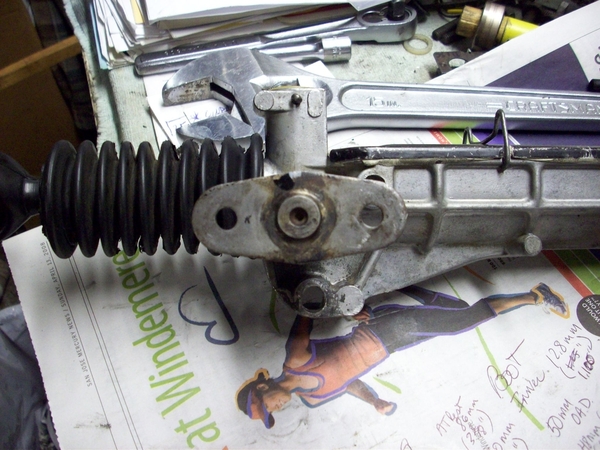
Here are a couple of photos, but I must advise that they are not the best and I was lacking the foresight to take more pic's of the rack deshrouded!!!! Duh!
I added pic's of the frame mounts for this style of rack. It appears that there is a needle bearing on the steering shaft.... I don't recall what the shaft rode in, in the housing. Didn't seem like much at all....perhaps right on the aluminium?
There may have been some tensioning wipers under those towers that appear on either side of the cover. Again, my apologies for not using more bits in the camera to catch this stuff!!!! Someone, please fill in my blanks!
Attachments
Steve I think you are right the inner tie rods are Unibal heim joints and they were available quickly at a resonable price. What needed to be done was re-thread them as the component had been modified by Ghia. In my case the rack, booties and outer tie rods were all in fine shape. I remember Dick R posting the booties were still available aftermarket from European but they call them « gaiters »
Denis,
OK, good to understand! I didn't want guys to grab parts expecting that they were going to screw right in....... when these are anything but!
Ciao!
Steve
Denis and Nate, thanks this is what I remember also--that heims don't exist with the combination of Eye and Thread (so to replace, must start with a big heim and decrease the thread)
Rd rebuilding the steering rack, if you want to choose an alternative route and go to a close ratio rack, I had a company in UK that does motorsport steering design and manufacture a closer ratio rack to the same dimensions as original. I believe they export worldwide. If you or anyone is interested message me and I’ll set you up with the company as I “own” the design but am happy to make it available to any Mangusta owner. I think it’s 2.5:1 vs 4:1.
cheers
Larry
Larry,
I believe the racks on Panteras and ("most") Mangustas are like comparing apples and carrots. This discussion has been had in the past....
BUTT, I cannot speak for later versions of the GOose racks.......
Never had a problem driving our Goose with the factory rack.......plenty of problems everywhere else......! ![]()
![]()
![]()
IMHO, anyone needing a closer ratio rack is starting to think crazy thoughts about they expect to drive their cars.....which will cause problems in every other suspension component on and including the chassis! Tissue paper.....!
Keep in mind, the Goose is now a rolling 401K plan!!!! ![]()
Ciao!
Steve
So Steve, is the long and short of it for restoration of steering:
On each end...new outer tie rods, try to get lube into heim between inner tie rod and rack, new boots/gaiters filled with some lube on end of rack rod, and lube inside the main portion of rack.
I'm guessing at what I did back when I did it, but that's pretty close! After 30K+ miles as the car came to me...and with a few more.....I was amazed to find that my tie rod ends (outer) were still in really nice shape! Also amazed at the condition of the modified inner Heim joints, needing only grease and new rubber booties!!! I was not thrilled with the idea of having to find someone to cut the Heim threads to a smaller metric diameter/thread pattern. But didn't need to worry as there was no need.
As for the rest of the rack, there really wasn't much one could do! Lube the steering sector or input shaft..it only goes in one way(!)....so I believe I laid in mass quantities of grease-ish substance....don't recall using any oil of sorts......
I figured that if there was grease on the inside.....it can work itself outside....so I didn't see any need to fill the rubber bellows with something that was gonna end up all over my floor pan, oil pan, and rear suspension!!! ![]()
![]()
![]()
This is a very simple steering rack.......and I guess I was thankful for that!!! I concentrated on getting the rest of my a-arm heims and ball joints sorted out as they were in TOUGH shape!!! New ball joints were needed immediately as were a couple of the heims.....the nylon "T" bushings were in good shape. I replaced them with new....but turns out they weren't good for any positive change....could have left the old ones in place......! Not a fancy front suspension!
Attachments
Finally, after 8 yrs and 8 months, should have goose back next week!! Only items missing that shop is having made to give me after the fact are the chrome trims for the rear wing side windows. They lost windows and trim in the process. Since replacements were unobtanium, found replacements in plexi in uk. They look good.
Also, now have all four original rear latches! Paint shop found last one in pass compartment.
Hard work to begin now!
Attachments
Lost parts.......ugh!!!! How the shops miss-manage in order to do this....! So many stories across the industry......
Great progress otherwise!!! Very exciting to have it back in your shop soon!!!!!
The final assembly with my car was always fun....even though I never was doing a full resto.....but just with the engine rebuild, or the ZF, or the brakes as small projects...the last jackstand pulled out and the car lowered to have rubber meet the concrete was a good feeling!!!!
Jump in the car and turn the key.....go for a drive!!! NEVER a bad day when you can do that! ![]()
![]()
![]()
Cheers!
Steve
Just found this thread… what a great read!!
it’s amazing how projects slowly morph into a decade long endeavor…
Also the hunt for parts is exciting and frustrating at the same time… but, at least for my Pantera - Fiat-Group parts from 1968 seem to be most of the times a winner.. tiny Fiat 850 being a donor included..
beautiful car! Now the tedious work begins for you … 👍👍
Goose gets delivered Thursday! Have new front trunk and door rubber trim purchased years ago from Cicognani to install to protect paint. However, painters lost all trim around engine compartment. Can someone shoot me a pic of the rubber trim that attaches to the body on which the rear wings rest on? Thanx much.
Rubber seals in previous input taken care of....
Does the following flow of rebuild make sense? Any major muscle movements left out?
- Check all wire continuity
- Refresh front suspension and refresh steering
- Brake rebuild/overhaul with new brake lines
- Clutch lines rebuild
- Rebuild doors
- Refresh interior
- Run rebuilt motor with all cooling and ignition from car on test stand
- Refresh all hoses
- Move motor, cooling, ignition from test stand to car
- Lights/horn/electrics, grate, trim on front end
- Lights/electrics/remote starter/battery on rear end
- Install exhaust system (possibly rebuild new exhaust like Dick Ruzzin's over the top bundle of snakes due to width of Boss 302 heads)
Congrats, car & color look fantastic!! Please keep us posted as the re-assembly moves forward!
Hopefully somebody has a solution for that elusive seal - - I've never gotten any handle on what the original version (if any...) looked like. My car came with a strip of urethane foam, ~3/4" wide, adhered to the body surface, in that small 'valley' just ahead of the pinch weld. Height varied across the length of this strip, depending on the size of the gap to fill. (IIRC it was thinnest across the roof area, and significantly thicker along the two sides). Maybe it served a purpose but it didn't look like an OEM feature.
All I know is that originally there was a faux-chrome plastic edge-bead along the pinch weld flange, where you have the seal installed. The available clearance over the flange is minimal (especially at the top corners of the cabin area), so nothing thicker than edge-bead fits.
So for an original look, faux-chrome beading is a 'yes', gasket/seal is a '?!? '


