Hi all,


I've got head light motor problems and believe it's due wiring issues. :-(

I badly need all you wise fellow Pantera aficionado's help. 


I've got a Pantera from 1974, I don't know if that's an early 1974 or 1974, in case that's important.

I've tried to research alot, esspecially on the other technical article here in the forum and also eg Pantera Palace. I've tried several times to understand the wiring diagram for an 1974 and comparing it with my wire harness, but still without success. But at least it looks like my wire harness is the original one.

I've seen the there two different types of head light relay,  the D16Y and D46Y. I believe I've got the latter, but I not 100% sure honestly.

I know the head light work. Both the actual light in the head lights because I can see there's light in them when I turn on the head light switch. I've also tested the head light door motor, with separate wires and a 12V battery. Motor works both up and down. And I've tested the limiting switches for continuity and those are fine both of them. The head light switch is brand new, that should be all good. And when I turn on the head light switch I can see and hear the head light relay engages. And releases when I switch off. So I believe the head light relay works.

BUT not matter what, the head light doors don't open or close. They stay closed.

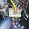
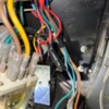
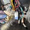
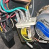
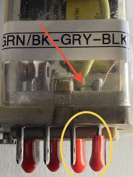
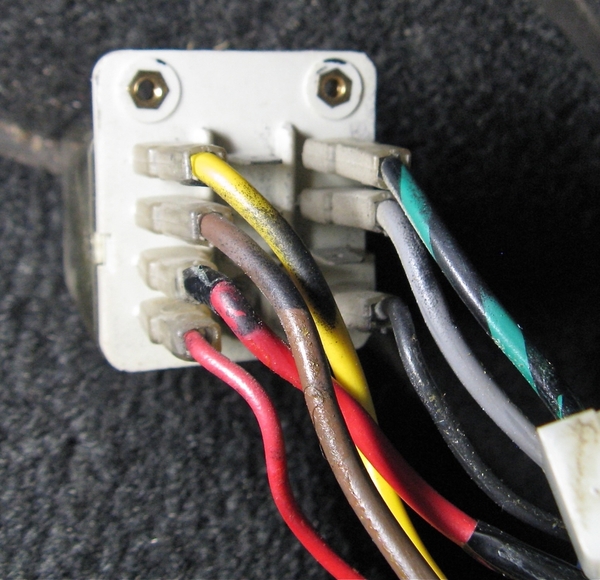
I've inspected the wiring at the head light relay and toke some pictures to share with you.

A few things puzzle me:

1) Why is the R/BK wire not attached to the relay, it's duc taped, but just beside the relay?. I would assume it's suppose to power the head lights but haven't dared to hook it up, because it looks like it's delibrately duc taped.

2) What's the story about the circuit breaker? I can see it's wired up to the green wire in ignition switch connecter block. But it's not hooked up to the head light relay. I forgot to take picture of it, but it was screwed to the head light relay, two wires  comming from it, one to the green wire  in ignition switch connector block and the other wire was just a lose wire.


I'll stop now, since it's already a long post. Hopefully some can help me get further. Thx in advance.

Attachments

Images (4)
  • IMG_8009
  • IMG_8011
  • IMG_8012
  • IMG_8007
Original Post

Replies sorted oldest to newest

First off, have the headlights ever correctly operated during your ownership or is this a recent equipment failure?

Your troubleshooting steps have covered just about every base short of wiring harness continuity. 👍👍

when you say you have checked the Continuity switches, that means you’ve checked them to confirm they can attain both open and closed positions, right ?

studying your photos I think you will correct your problem by connecting the red/black wire to the terminal between the red and brown wires. The red/black wire connects to the relay terminals, the smaller red wire connects to the relay coil.

The twinned black wires require you to look through the cover of your relay to see if there is an internal jumper from these two terminals.

A0F770B2-688A-4F9A-BF39-862D2E78E86E

If there is a jumper then you are good to go. If not, you need to add that jumper or split the two blacks and connect one to each terminal.

One additional suggestion. If you have the jumper, it is better to connect the two black wires to the terminal next to the gray wire. That is the terminal that connects to the relay points. If you connect to the terminal as shown in your photo, with an internal jumper, you are running the headlight motor power through the small internal jumper - hi amperage with small wire should be avoided.

Larry

Attachments

Images (1)
  • A0F770B2-688A-4F9A-BF39-862D2E78E86E
No I mean the empty terminal between the yellow and red wire.
On Sunday, May 21, 2023 at 08:41:11 PM PDT, The De Tomaso Forums <alerts@crowdstack.com> wrote:


| == To reply by email, write above this line. == |
|
You Were Mentioned
|
|
You were mentioned in the following post:
|
| Head light motor problemsReply by lf-tp2511
@forestg posted:
The loose wire from the circuit breaker needs to be connected to the relay terminal next to the yellow wire. That is the 12v+ for the motor.


Don’t you mean the empty terminal next to the brown wire?

Larry

[ View Reply ]
|
| The De Tomaso Forums
You received this based on your notification settings. You can adjust your settings or unsubscribe anytime.
|

See tech service bulletin 14 page 14. Fig 19  and 18. The photos he provided show that the brown and grey wires are in the middle of the three terminals and the yellow green are on the outer terminals as shown in fig19. The circuit breaker loose wire is the one shown in fig 18 not going to the common terminal of the tpdt relay but that is where it has to go. Kind of a hybrid of the two figures. Also the black wire should be connected to the terminal next to the green wire.

Last edited by forestg

Forest,

I think we are in agreement the two black wires should move over one terminal.

I think the red with black stripe wire, currently wrapped in electrical tape, should be placed on the empty terminal next to the small red wire.

you think a wire coming from a circuit breaker should go next to the small red wire. I don’t see a circuit breaker in his photographs.

Are we talking about the same wire just describing it differently?

Larry

See attached excerpt from TSB 14. His description of the wiring and circuit breaker seems to indicate that this modification has been done. I don't know why there is a difference in the location of the yellow, green, brown and grey wires between figures 18 and 19 but I am assuming that at one time the lights worked as wired and that somewhere along the line the power wire from the breaker has become unhooked from the relay. by the way, the relay coil wiring in fig 19 is not correct. It shows that both terminals of the coil are connected to power. The black wire should be jumpered to the relay coil unless internally jumpered.

Attachments

Files (1)

It appears that the relay shown by the OP is a D16Y early relay.  

The D46Y relays have a black (opaque) cover, whereas the D16Y relays have a clear cover.

The only wire that is not connected in the pic is the red/black wire with the tape.  I suspect that the TSB has not been performed because this car came with the early D16Y relay.

I would do as Larry posted and connect the red/black (taped) wire to the terminal between the small red wire and the brown wire.

The ignition key needs to be turned on for the headlight buckets to raise and lower.

John

Hd Light Relay Wiring

Attachments

Images (1)
  • Hd Light Relay Wiring

There he is 😁😁

and I still think it is important to know if you have ever seen the headlights raise and lower or if this is a problem that recently developed  

to review, I think you need to put the red/black wire on the empty terminal next to the small red wire. And you need to move the two black wires to the empty terminal next to their current connection

🤞🤞🤞

Larry

:-)

I'll try to answer all the great questions asked. Bare with me if I miss one or two. Just ask again.


First if the headlight ever has worked in my ownership.

Answer: Yes - they have, But it's always been weird, sometimes they would work, other times not. Sometime the headlight would be able to get up, but not down again, before suddenly they would go down without me pushing the head light button. So they have also been acting a little weird. Then suddenly they never worked anymore.

My initial thoughts after reading some forum posts was the that it would be the head light switch, since I read these where prone to break due to all load being send through them. So I bought a new head light switch and believe all would be good. Nothing changed. :-/

I then read more forum posts, and read the fuse box would be prone to cause problems. So I turn to Pantera Electronics and bought that one and installed it instead of the original fuse panel. No change! :-/ But at least that installed now as well.

I then bought the head light motor controller (HMC) from Pantera Electronics because I read it would be good to remove the high load on the head light button, wanted to install it, but then read the instructions which said, don't install if the head light wasn't working already. So then I've not dared to install it yet unfortunately. Especially because I scared of frying the HMC which wasn't cheap.

So now we are back to currently time, me trying to find out how to make the head light door up/down work.

Ps: Btw the head light lightning has always worked. No matter if the head light motor door worked.


I'll answer next question in new thread...

On the limit switches - and if I checked them for Continuity.

Answer - Yes, I've measured them with the original wires disconnected and just attached the wires from the multimeter. If I remember correctly the switches was short circuit when they where open and close not connection. I might remember wrongly, but not important, the important is there an change in continuity when pushed and it goes for both limit switches.


New thread for next answer... :-)

On the R/BLK wire.

I also was pretty sure when I saw it lose (but with duc tape), that would be the solution. BUT then I was thinking, why would someone remove it and duc tape it, unless it was deliberately. And if it was done deliberately, what would happen if I connected it. So I decided to read some more posts and found this one.

See attached image, it's a technical bulletin.

And it seems to indicate the R/BLK wire shouldn't be attached and be duc taped, just like mine is. Then I got more confused. And didn't dare to attach the R/BLK wire to the head light relay after all.

Attachments

Images (1)
  • TSB_116-6

A quick question from me.

- Does there exist a cheaper newer replace head light relay? Or is my only chance to buy an old D16Y or D46Y relay?

I want to order one in case conclusion would be the relay is broken. But since I got the HMC device, didn't want to buy an expensive old head light relay that might just go to the shelf.

Next answer, from and image above regarding if I got D16Y or D46Y.


The twinned black wires require you to look through the cover of your relay to see if there is an internal jumper from these two terminals.


Answer - actually there was a small bridge wire between those two. Hence I concluded it is a new relay. But during my investigations (don't ask!) I manage to do a small short circuit which fried that little small bridge wire. Which of course potentially have ruin the head light relay, unless of course it's enough I just do a wire between the two myself. Wouldn't be that difficult to do after all.

Answer to this:


It appears that the relay shown by the OP is a D16Y early relay.  

The D46Y relays have a black (opaque) cover, whereas the D16Y relays have a clear cover.


True, my head light relay have a clear cover. It's not black.


I hope I've answered all/most of the questions I got in the thread. Once again THX all of you to be so helpful. I'm impressed by all the posts for trying to help me!! :-) :-) :-)

Add Reply

Post
×
×
×
×
Link copied to your clipboard.
×