Is there any maintenance needed on the linkages or shafts on IR injection systems?

My throttle is hanging up. Throttle blips are extended for a second, resulting in a long high rev.

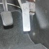
Looking at the pedal, it and the cable are such that they can possibly hang up on the console side cover, something I'm looking into.

I was wondering though if there was any periodic disassembly or greasing of shafts or anything I might need to be doing to my IR system.

The linkages are heim joints, which I don't think you lube at all, but I don't think that's my issue. I think my issue lies with the pedal or cable hanging up on something, but it made me think about anything else I should be doing to maintain my injection on my car.

I'll be taking the pedal and cable off and inspecting/replacing the cable if it's anything but perfect.

The center console side cover is shaped such that there's a corner that can catch the pedal under the right conditions, so I'll be checking that too.
Original Post

Replies sorted oldest to newest

Thanks for the tips. I though smaller heim joints always were not lubed to keep the wear down.

I have some chain wax I can use, along with 20 other lubes that would also work.

I'm taking a break from the car for a while.

Trying to drive it weekly has me chasing one thing after another, it making me have bad thoughts.
My experiance with similair rod end brgs is not fuel linkage, but I would say they NEED to to be lubricated. Oil is not going to stay and will require more frequent application. I would prefer a dry FILM, thus the lubrication with less attaction and retention of dust and contaminates. grease would be the most recomended.

I can't tell from the photo, but the assembly of rod end connections does require a certain amount of consideration to ensure force is transmitted with out binding. I have seen linkage design and sold for mega bucks that required corrections to make it operate proper. I have some good war stories about such.

and back to your original query...Dry is bad unless the rod ends are pre lubricated with a dry film coating or either the ball or race is made from a low friction material. the steel on steel or steel on brass would benifit from a perodic lube
Yes, i can not imagine why they should be run dry.

Maybe in a very dusty situation where the oil might attract and hold on to dust, but your engine looks pretty clean, and i would not think that you drive your Pantera in the dirt so a drop of oil is a good thing.

Use oil, you will be lucky to get any kind of grease into them. You are asking about "maintenance" this is maintenance.
Ps: i do not like where that spring is attached.

From the photo it seems like it is hooked around the bolt holding the heim joint, the hook of the spring could get hung up on the linkage or perhaps the side of the joint itself.

Springs should have dedicated mounting points, not just be hap hazardly hooked onto any seemingly convenient bolt or piece of metal.

This type of thing is the cause of many "sticky" throttles.


The Devil is in the detail.
It's appears in the photo that the spring is rubbing against the linkage rod.

Plus the "90 degree bend" in the spring should be CENTERED in the spring, NOT at the outside edge of the spring.

Centering the bend in the middle of the spring, gives a direct pull as opposed to the FLEX the outside current bend will exhibit...Mark
I haven't messed with the linkages or throttle yet.

I used my unisync tool and all holes were close enough to each other to not need to touch anything.

I also found out just how sensitive the system is, micro screw adjustments made big changes so I put everything back exactly how it was. I actually lucked out and it idles and tad smoother now lol.

I'm having issues with my throttle sticking, but I have to check my pedal and cable first before anything. Once those check out, I may look into having an expert adjust the linkages and hopefully tune my ancient Haltech ECU.

I believe my pedal or cable is hanging up on the side center console cover. This issue arose only after I removed and reinstalled the console side cover.

The way this car has been going, I touch one thing, and it causes 10 new problems, so presently I'm going to inspect things VERY closely, as I CANNOT have a sticking throttle, obviously.

The spring, and all linkages are as I bought them, so I have no way of knowing if anything is correct, but it's good to know I should lube my heim fittings.
quote:
I believe my pedal or cable is hanging up on the side center console cover. This issue arose only after I removed and reinstalled the console side cover.

It's an EASY fix to make sure your gas pedal is not hanging up on the plastic panel on the side of the center console. Simply add a screw and a washer to secure the panel and it will afford you an extra inch or two of clearance for your shoe on the pedal.

Attachments

Images (1)
  • kick-panel_modification_640x480
First off, the heim joints are stainless steel balls in nylon races. You do not lube them at all.

Second, if the throttle linkage is assembled correctly it should work free and easy with just the return spring in the Pantera throttle cable.

If you will remember, I have previously advised that you need to determine if it is the throttle cable that is hanging up.

You do that by disconnecting it from the throttle bodies and operating it. This will at least eliminate that cable from the issue if it is ok.

It should work easily and snap back when you release the pedal. There shouldn't be the slightest indication of it hanging.

If it does hang, you have two choices. Fix it or replace it BUT remember, these cables have an inherent internal issue that the new one will also have. Fixing that issue seems to me to be the permanent fix?

The other thing is that with a throttle return spring in the linkage of too much pressure OR in the WRONG location, you could have worn throttle shafts in the throttle bodies themselves.

Do the throttle cable test. Then go to step 2.
Thanks Doug, that's exactly what I plan to do.

I am aware that too much spring will wear shafts, and thanks for the tip about the heims.

They looked to me like the type you don't lube.

I'm dealing with the car as it was sold to me, so everything is as Roger had it, correct or not. My intentions are to get everything right, but there's a lot to do.

I'm going to disconnect the throttle cable and check that it's moving freely or replace it.

I'll also add the screws to the side panel, my car didn't have any screws there.
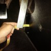
Here's a pic of the throttle cable routing as it goes to the linkage.

I also noticed what looks to me like the fuel rail is leaking, between the cast pieces, where the tube sticks in.

If I go pulling this stuff apart, am I going to be able to find O-rings and whatever I need to put it back, leak-free?

Attachments

Images (1)
  • fuelrail1
I will probably pull the seats and firewall upholstry, so I can remove the throttle cable and inspect it properly, replace it if necessary.

Now I've found this leaking fuel rail, this car is overwhelming me with sh!t to do on it!

I got the electrical figured out finally, now it's on to the throttle cable and fuel rail, then hopefully find somebody to help me tune the ancient Haltech system. I'm OK with it running fat though, the plugs show it's running OK so the fatness is just idle and feathered throttle.

I love working on cars and stuff, but the enjoyment time-to-work on the car time ratio is off kilter.

I'll get it straightened out soon enough.
I can't answer about the cable function because I simply would never engineer one like that.

I would use a bell crank.

I do think that it is highly likely that is where you binding takes place.


Just pull the fuel rails appart and change the o rings. That's all that is in there. Nothing fancy.


You have to be running around 40 psi for fuel injection, so even just a drip isn't going to remain a drip for long.

I have flooded the intake manifold with fuel ON A HOT ENGINE! I saw my entire life pass me in just a micro instant.

The fumes took at least 100 points off of my IQ permanently. Now I am left with less than 1/2 of a brain, which I am sure surprises no one?

You DO NOT WANT TO EXPERIENCE that. It is at least 10 years off of your life.
OK, well that's good to hear.

I can take stuff apart no prob, been doing that since I was a wee tot. It's getting it all back together that's often the hard part.

I'll take the fuel rail off and fix that. Fuel pressure runs around 42 I believe. I just noticed the raw fuel around the cable guide today, as I started chasing the throttle cable issue today.

BUT, since now it's gonna be a pull the seats and firewall and remove the cable ordeal, along with repair of the fuel rail, once again it's gonna be a while before I get to enjoy driving Snow White (it's actually not that much work, just sucks to do it alone).

We're still within the realm of stuff I can do myself, it's down to motivation and interest now. I'm getting tired of working on the car.

Might just take a break for a while
quote:
Do most people do away with the big metal cover, and just mod their upholstery hump so it velcros or snaps in place?


I can't speak for most people, but I don't thing most people are running without the metal panel.


I have a flattened metal bulkhead cover. Now you can't just "make one" - it requires some mods to "outboard" your alternator, and maybe your A/C Compressor.

The "hump" on the big fiberglass panel is (one of) my next project(s).

Just to torment everyone (and to show off the work of my friend and mentor, Wade - a.k.a MarkIV/4280), I will post up another link to my build thread. If you scroll about 1/2 way down, you can see the flat bulkhead modification. On page 4 of the thread, right at the top, you will see pictures (and discussion of) the outboarded alternator and Sanden Rotary A/C compressor on the engine before we installed it.

Now I need to make the fiberglass cover match the profile of the inner hump, and make the outer "hump" removable with Velcro.

Once this is done, my passenger gets about 3" more legroom and/or recline, and I get easier access to the front of the engine bay.

Scroll About 1/2 Way Down to See the Flat Metal Bulkhead...

I recommend you also look at page 6 (down at the bottom) - there is more pix, and a like to David Nunn's setup.

This is how we did it - I am sure there are other ways to skin this cat.... (get it?)

Rocky
MtS,

I am curious and would like to learn something about an IR setup, so I'll have some questions.

Is the "idle" speed set by adjusting the opening of the butterfly plate and balancing air flow?

IF so,

is the butterfly opening a "stop" adjustment on each shaft?

is the linkage disconnected when setting idle to ensure it does not hold a butterfly off its idle stop?

when you get a chance, a photo showing the detail of the rod end bearing's connection to the throttle shaft arms would be nice
I'll gladly take more pics, but there are many adjustment screws. I have an OK idea as to what each screw does.

I do believe there's an adjustment stop on each body, and also a main idle adjustment screw as well.

Some of the screws are to balance between the front and rear pair of IR's, I believe the cross shaft adjusts the balance between the two sides, and there's a main idle adjustment somewhere as well.

I started to try and make sense of it, but all the holes showed so close with my unisync flow tool that all I touched was (what I think was ) idle, and it was so sensitive, i put it back where it was and decided when thwe time came I'd throw the car at someone who knew their way around these systems.

I also need a tune BAD, but my Haltech is ancient, and I need to find a program that makes a newer computer appear to be running DOS so it can communicate with the Haltech, then a tuner acn make adjustments.

THEN I need to find a tuner who knows his way around tuning IR systems like this.

This is plan A.

If enough time goes by, or I can't keep the car running, I'm going to wait and save and upgrade to newer electronics and tune that controls both ignition and fuel. This is Plan B, but that won't happen until after I rebuild the engine.
Ok, i"m trying to address the sticky throttle and leaky fuel rail.

The rail leaks between the two halves, that are joined by a smaller diameter tube.

This tube spun easily with my fingers, so the O-rings must be old.

There's a plastic retainer tab on each side of the center tube, with a screw.

I'm wondering if this tube can be removed and O-rings replaced without having to completely dismantle the entire fuel rail.

Maybe the plastic retainer will allow the center tube to slide inside one half enough to allow the new O-rings to be installed, and then the same done to the other side, and then the plastic retainers keep it all centered somehow?

The rail on the other side seems to be extruded or soldered or made into the main part of the rail at least on one side. I didn't look as closely at that side as it wasn't the side that was leaking.

Attachments

Images (1)
  • leak1
Here's another pic of the plastic retainer, with the screw that holds it in place.

The center tube spins easily by hand, and seeps fuel, so the O-rings need replacing.

I'm just wondering if it can be done without removing the whole rail system, or if the center tube can be slid back and forth enough to remove and replace the new O-rings.

Attachments

Images (1)
  • leak2
do you think the fuel rail is off the shelf or custom made. Just looking at the photos, both the tube and the rails look thin to have an oring seal. I would invision that the oring could be installed either of two ways. and I would expect the tube could be slide to allow acces to one end at a time. I would hope the oring would be on the OD of the tube as trying to hoke out one from the ID of the rail would be dificult with the limited access

I would say try

Attachments

Images (1)
  • fuel_rail
I think the tube is probably flared on each end and sits into a machined inverted flare seat similar to a Holley carb with a tube nut.

There is no compression fitting because the mounting of either extrusion is held firmly in place by the mounting to the injectors and there are probably mounting tabs on each extrusion as well that bolt at some point to either the throttle bodies or the manifold.

I looked for details on that particular rail but don't see any.

If you get stuck on something try Dennis at Colorado Pantera Performance. He most likely did the original design on the system.

The Byers brothers at Precision Proformance probably know as well.

Neither of these guys like to post details like this on the internet.

I personally would remove them both of the rail assemblies and replace all of the orings in the assembly.

They are highly likely just off the shelf items you can get at any auto parts dealer in the "o-ring" assortments variety packs.

Here is where you get to use that little ratcheting 90 degree screw driver to get those screws out. If you happen to strip them, then you will discover why people use a torqs head bolt in there?

It should not be a major ordeal.

There will be a short learning curve.


Those fuel rails look like the REDLINE fuel rails.
http://www.carburetion.com/Weber/wildv8injection.asp
They’re TWM (now Borla) throttle bodies of the same era as your Haltec ECU. The fuel rail kits were standard items and the old TWM website use to have an exploded view and illustrated parts reference that called out each fuel rail part by number. I don’t believe the new site has this reference or if it does, I could never find it. In fact, though Borla have large bore IDA TBs listed, I’m not even sure they list the 48/50mm IDA style TBs anymore, but they do offer them on their “V-8 systems” which still have similar style modular fuel rails.

The next generation of their hardware used similar modular rails but the rails were mounted inboard and the ends had modular caps that tied the rails together and also allow mounting of other components such as regulators, gauges, sensors, etc.

That tube in your picture just has O-ring seals to each fuel rail and floats between the two rails so as to accommodate intakes with different center line distances between TBs.

Just replace the O-rings. It’s a 15-30 minute job to remove the rails, measure and buy a couple 25 cent O-rings. If you remove the two underside screws that mount each fuel rail, both rails on the bank will lift off the injectors and then use an offset or ratchet screw driver to remove the inside retaining caps. –Replace O-rings reverse assembly.

K

Add Reply

Post
×
×
×
×
Link copied to your clipboard.
×