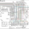
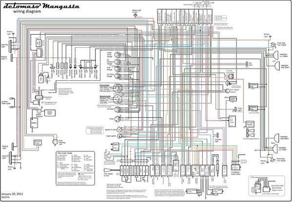
wiring diagram colorized 1_20_19Attached for peer review is a wiring diagram for the Mangusta.

This is the result of a collaboration between Lee Atkinson, Nate Stevens and myself.  We have tried to include each variant and option along with part numbers if known.

We have included wire colors, fuse ratings and connection blocks.

Please feel free to review and comment as we plan to submit it to Provamo once everyone feels it is accurate.

Enjoy!

MH

Attachments

Images (1)
  • wiring diagram colorized 1_20_19
Last edited by George P
Original Post

Replies sorted oldest to newest

mkeh posted:

Well, it appears that the image is being compressed. 

Can the moderators allow a larger attachment?  I have it down to 256k

resolution is 3040 x  2107

MH

File size does not appear to be the issue. For instance Lee's PDF is 1.39 MB.

Getting an image that is 3040 x 2107 pixels down to forum size, and still keep the detail read-able is going to be difficult. The font size of the text looks too small for one thing. You can not "zoom-in" on the embedded images or the larger pop-up images.

 The embedded image is about 589 pixels width, obviously it must be that width in order to be embedded within the content box. When you click on the embedded image another larger image pops-up … but there are limits to the size of that pop-up image too … the software will reduce the size of the image to fit within whatever the limits are. The pop-up of the schematic's image is 1000 pixels wide right now.  1000 pixels width is most likely the width limit. I do not have the option to adjust that limit however. 

The PDF that Lee posted looks good, and you can zoom-in to see detail.

I shared some ideas with Lee via PM on how to best resize the PNG or JPEG files, but I suspect you're not going to be able to read the text, and the lines will be so close together that it will be hard to follow them.

Last edited by George P

Guys, lots of questions we had while putting together details, always appreciate if someone can help us fill in the blanks. The drawing now represents everything we could pull together, from the factory drawings (the "Italian" factory drawing dated November 1968, the undated but we assume earlier Hall trace, the Goose parts manual--but then every picture we could find of the Goose, other same-era wiring diagrams (esp Fiat 850/124, Lotus, MGB, and especially the Maserati Mexico/Mistral/Ghibli GT family which lent their fuse box to the Goose. Lastly, 5 cars that are/were physically in our own hands---but 4 of these 5 all from the 8ma10xx production range, and we're especially curious if there were changes after ~8ma1100 and especially the last German cars. 

1. Headlight "flash"; Are "brights" with stalk forward or middle ?  We've had at least one confirmation (from Denis' German made 1244) that stalk forward turns on brights, but 2 other cars where stalk forward=low beams. Also, the "Italian" drawing and manual show a Carello relay used for turning on Low beams whenever flash (stalk pulled back). How does your car work ? 

2. Window motors; late Goose and Pantera had "2 wire" window motors, but 3 wire motors were clearly used on earlier cars. We assume that the transition occurred around ~8ma810 (with the change from the Ducellier chrome bezel pair-of-paddle switches to the stainless bezel 2-each Ducellier switches). Any idea ? We'd like to capture wire colors and also confirm the grounding position on the Black wire inside the door on the 2-wire cars. 

3. City horn; We only know of the Bosch IGM3572 for the City horn, most cars used these in pairs with low of 270hz (around a C-sharp) and 400hz (around a G-sharp) but the Goose had only one. What's in your car ? 

4. Options that never were...Seemed to come from the Maserati drawings. 

a. Parking brake light did exist on very few cars, as we can tell a handful of the earliest (508, 518) and then the much later Bordinat car. Lotus Elan used the same parking brake umbrella handle and the S2 had used a Lotus switch on the umbrella bracket, would love to see any pictures of Goose parking brake switches. The lamp itself looks like the variant used for Mistral. 

b. Alternator; seems to have been Prestolite (with 4 wire voltage regulator) on maybe the first ~50 cars, then moved to Bosch. Can anybody confirm this? 

c. Reverse lights; as we can tell were implemented only on the Pantera. 

c. Antenna motor switch and wiring; Would be interested if Anybody has ever seen a factory installation. 

d. Voltage stabilizer for the gauge power; was used on first mid 60's Maserati with Smiths gauges, but as we can tell was never installed on Goose (that used the Veglia gauges operated directly off battery voltage). 

e. As noted in another thread, the windshield wiper motor was recorded as 4-wire Lucas, and the November 1968 Italian factory drawing shows the 5-wire "self parking" motor. We assume the Italian drawing is later because of this, even if it didn't capture changes (esp. the Alternator).

f. fuel reserve light; is everywhere except the fuel gauge...The sender has the terminal, the wire is in place, but even some Panteras did Not have a socket for the low fuel lamp in the gauge.  

G. In the only interesting category;

 - As Wellis reported, yeah, the City/Horn switch is exactly the fuel pump switch used on Ghibli (not just the same icon). 

- early Ghibli used the same Lucas toggle switches, but they added a 2-speed heater fan switch the Goose never received. The Hall drawing doesn't show the switch at all...Would be curious is the Goose originally had a speed-resistor for the heater fan and anybody had a 3-position heater switch. 

- generally, the Maserati used more relays, and probably lowered the current thru either the turn-signal stalk and ignition switch. If you don't drive your Goose at night much (and don't really use the lights) this probably isn't a worry..But if interested, there could be a couple places to insert relays and relieve these (just about impossible to find in original spec) switches of stressful current without cutting any old wiring.

  Btw, our only apology was that we left everyone else out of the fun....Months ago, I'd mentioned to Mike that I dreamed of someday redrawing the wrinkly, low contrast original diagrams---and Mike had already done it...! With a beautiful, clear drawing in hand I started burning end-of-the-year vacation time to understand it, then thought in my newfound wisdom I may show off to Nate--but another pot of gold there, Nate's knowledge of the wiring harness and its peculiarities was extraordinary, meticulous, and so carefully preserved...so that I can really trust that now we've made an accurate capture. Almost every day for 3 weeks, we had a constant exchange of head scratching between the 3 of us, and almost daily revisions of the drawing...But what a thrill to see if improve day over day. Hope each of you can join the fun, while things are fresh in our minds whether you have a question, an observation, esp a correction, we'd love to know... Lee
Last edited by leea
leea posted:

Guys, lots of questions we had while putting together details, always appreciate if someone can help us fill in the blanks. The drawing now represents everything we could pull together, from the factory drawings (the "Italian" factory drawing dated November 1968, the undated but we assume earlier Hall trace, the Goose parts manual--but then every picture we could find of the Goose, other same-era wiring diagrams (esp Fiat 850/124, Lotus, MGB, and especially the Maserati Mexico/Mistral/Ghibli GT family which lent their fuse box to the Goose. Lastly, 5 cars that are/were physically in our own hands---but 4 of these 5 all from the 8ma10xx production range, and we're especially curious if there were changes after ~8ma1100 and especially the last German cars. 

1. Headlight "flash"; Are "brights" with stalk forward or middle ?  We've had at least one confirmation (from Denis' German made 1244) that stalk forward turns on brights, but 2 other cars where stalk forward=low beams. Also, the "Italian" drawing and manual show a Carello relay used for turning on Low beams whenever flash (stalk pulled back). How does your car work ? 

2. Window motors; late Goose and Pantera had "2 wire" window motors, but 3 wire motors were clearly used on earlier cars. We assume that the transition occurred around ~8ma810 (with the change from the Ducellier chrome bezel pair-of-paddle switches to the stainless bezel 2-each Ducellier switches). Any idea ? We'd like to capture wire colors and also confirm the grounding position on the Black wire inside the door on the 2-wire cars. 

3. City horn; We only know of the Bosch IGM3572 for the City horn, most cars used these in pairs with low of 270hz (around a C-sharp) and 400hz (around a G-sharp) but the Goose had only one. What's in your car ? 

4. Options that never were...Seemed to come from the Maserati drawings. 

a. Parking brake light did exist on very few cars, as we can tell a handful of the earliest (508, 518) and then the much later Bordinat car. Lotus Elan used the same parking brake umbrella handle and the S2 had used a Lotus switch on the umbrella bracket, would love to see any pictures of Goose parking brake switches. The lamp itself looks like the variant used for Mistral. 

b. Alternator; seems to have been Prestolite (with 4 wire voltage regulator) on maybe the first ~50 cars, then moved to Bosch. Can anybody confirm this? 

c. Reverse lights; as we can tell were implemented only on the Pantera. 

c. Antenna motor switch and wiring; Would be interested if Anybody has ever seen a factory installation. 

d. Voltage stabilizer for the gauge power; was used on first mid 60's Maserati with Smiths gauges, but as we can tell was never installed on Goose (that used the Veglia gauges operated directly off battery voltage). 

e. As noted in another thread, the windshield wiper motor was recorded as 4-wire Lucas, and the November 1968 Italian factory drawing shows the 5-wire "self parking" motor. We assume the Italian drawing is later because of this, even if it didn't capture changes (esp. the Alternator).

f. fuel reserve light; is everywhere except the fuel gauge...The sender has the terminal, the wire is in place, but even some Panteras did Not have a socket for the low fuel lamp in the gauge.  

G. In the only interesting category;

 - As Wellis reported, yeah, the City/Horn switch is exactly the fuel pump switch used on Ghibli (not just the same icon). 

- early Ghibli used the same Lucas toggle switches, but they added a 2-speed heater fan switch the Goose never received. The Hall drawing doesn't show the switch at all...Would be curious is the Goose originally had a speed-resistor for the heater fan and anybody had a 3-position heater switch. 

- generally, the Maserati used more relays, and probably lowered the current thru either the turn-signal stalk and ignition switch. If you don't drive your Goose at night much (and don't really use the lights) this probably isn't a worry..But if interested, there could be a couple places to insert relays and relieve these (just about impossible to find in original spec) switches of stressful current without cutting any old wiring.

  Btw, our only apology was that we left everyone else out of the fun....Months ago, I'd mentioned to Mike that I dreamed of someday redrawing the wrinkly, low contrast original diagrams---and Mike had already done it...! With a beautiful, clear drawing in hand I started burning end-of-the-year vacation time to understand it, then thought in my newfound wisdom I may show off to Nate--but another pot of gold there, Nate's knowledge of the wiring harness and its peculiarities was extraordinary, meticulous, and so carefully preserved...so that I can really trust that now we've made an accurate capture. Almost every day for 3 weeks, we had a constant exchange of head scratching between the 3 of us, and almost daily revisions of the drawing...But what a thrill to see if improve day over day. Hope each of you can join the fun, while things are fresh in our minds whether you have a question, an observation, esp a correction, we'd love to know... Lee

could the writers arrange to send me a copy of their wiring diagram. I want to compare it my own wiring diagram i have made over the years from the nine mangustas I have owned. Jerry McGlothin   1046 E. Driftwood Dr. Tempe AZ 85283. phone 928-853-0473.owner of 3 pushbutton panteras  106  185  1310 and one Mangusta   (pop up headlite model 8MA11xx)

mkeh posted:

Attached for peer review is a wiring diagram for the Mangusta.

This is the result of a collaboration between Lee Atkinson, Nate Stevens and myself.  We have tried to include each variant and option along with part numbers if known.

We have included wire colors, fuse ratings and connection blocks.

Please feel free to review and comment as we plan to submit it to Provamo once everyone feels it is accurate.

Enjoy!

MH

Very impressive. Thank you very much

Just reviewed your diagram.  Thanks for all the hard work.

I have a US delivered car with pop up lights  8MA930.  I puchasedthe car new and sold it after a few years of ownership..  I bought it back a few years ago .  This car has an electric fuel.  I assume they all do??.   The pump is not on your drawing.

Did the earlier cars not have an electric pump?


PPP


PPP, thanks, it was a lot of fun to piece together...re: the fuel pump, we don't have any indication that one was installed originally. The strange story is that yes, there was a Fuel Pump toggle switch on the dash, and the fuse box cover includes a marking for Fuel pump (Pompe Benzina) at fuse #11....But both these were simply inherited from the Maserati. Maserati had left and right mechanically separate fuel tanks, the switch would engage the separate Bendix fuel pumps and flip the fuel gauge to display the active tank. Ghia used exactly the same switch and exactly the same fuse box cover (the latter simply changed to remove the Maserati logo) between Ghibli and the Mangusta. But for the Goose, the (exact same part number) switch is used for the country/city horn switch (even though the Alfa horn switch had a real Horn icon, not a fuel pump!) and the F11 is used for the Air Conditioner instead on Goose...! Lee

All, this looks a massive help to any of us re-wiring. My car (1028) is ex race car with lots of chopped up working.  I have a new Loom  from a company here in UK which I’ve used and the diagram is really useful.

I have also had Jon Haas (what a super guy) make me a Pantera style blade fuse box specifically for the Mangusta 

i intend to make /mould a resin fuse box cover to fit over the new blade fuses (it’s slightly larger than standard) to retain a stock look.

im hoping it will be a big improvement in functionality and reliability over original.

jon’s work is absolutely 1st class 

i was planning on doing an article on the instal for this forum in case it was of benefit to others, but am not at that stage yet and as my car will do some races this summer may not change things (ain’t broke at moment etc!) until the winter 

i am overseas for a few days but will try and provide more info when I’m back 


cheers 

Larry 

 Suggest you move the switch while honking the horn   Funny that DeTomaso used the "pump' icon on the horn switch (switch position #6, the second from the right). I'm sure someone on the Ghia line got a promotion for simplifying one aspect of part management in the factory...!

  If you need an electric fuel pump, then Yes, my suggestion is that the power for the pump come from either position F10 or F11. But unless that switch is a kind of theft protection, you should not need a separate physical switch for a single fuel pump. The ignition switch for the Goose is simple 3 position Off/Run/Start, fuse site F12 is directly turned ON by the key when in the Run position and that connection switches the Carello relays that provide power to the F10 and F11 fuse sites. An electric fuel pump should use those fuse outputs directly or use them to switch another relay to take directly from Battery Power.  

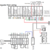
  There is no 'accessory' position for the key, but almost everything else (the electric windows and even the radio) can be used with no key in the ignition (Fuses 5-9 always have power). But for example, the "Country" horn needs to have the switch ON to operate (the city horn works all the time). attached is a simplified picture of the City/country horn switching, when in City mode the Bosch horn is directly grounded thru the steering column...in Country mode, the #6 (fuel pump!) switch instead activates the FIAMM relay behind the steering wheel, which sends 12v to the compressor in the right grille area.

See pictures showing simplified diagram for the Fuse switching and Horns attached !

Attachments

Images (2)
  • goose switched fuses
  • goose horn wiring
Last edited by leea

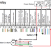
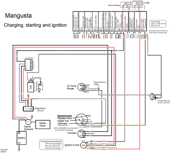
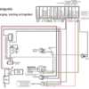
Attached is a functional excerpt, basically everything needed for starting the car and charging the battery...Maybe the most interesting thing here is the Alternator light, some detail that wasn't on the Hall diagram but also changed around 8ma1000. We left the "voltage stabilizer" in the diagram even though we have no evidence it was ever installed, however it seems that earlier Goose had an independent wire (yellow) from F12 to the alternator bulb. This would have been required if the Voltage Stabilizer was installed (since the voltage stabilizer drops the voltage to 8-10v, the Yellow wire was needed to provide a real battery reference for the bulb so that it would not always be ON...). But somewhere before 8ma1000 the wiring harness changed to create a stub wire from the adjacent Oil Temp gauge, and at some time (probably early 8ma10xx)  the Pink wire (also from F12) was used for the alternator light and at least by 8ma1046, the yellow wire was not installed in the wiring harness. 

 Note that an LED bulb can NOT be used in the alternator light, an LED is a diode and a bulb is needed to conduct current in both directions.  Pantera included a 15ohm resistor (13005A) across the bulb, so that even if the bulb burns out there is an electrical reference back to the regulator. Also to emphasize, the lamp socket used here is different than used for all the other gauges (which ground one connection of the lamp to  chassis thru the gauge can...). For Pantera, this is 13006B "dual terminal," the physical style was different on Mangusta but either should work. 

   Mangusta charging starting and ignition


Attachments

Images (1)
  • Mangusta charging starting and ignition

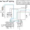
  I started a 'simplified' breakout of the lighting diagram for the car, but hope that breaking this into 3 pieces is a bit clearer. Specifically, here is the "key off" lighting diagram. Its a bit strange that most accessories in the Goose (windows and radio) operate without a key in the car, but that most of the lighting does NOT work unless the key is "on"...And this even applies to 2 of the courtesy lights (the one in the trunk, the other in the engine bay. don't adjust your set, your bulb is not bad---but even though those 2 lamps have their own switches, in fact the car ignition must be ON and the parking lights switched ON for those lamps to operate---and since you do not dare turn the key to ON without actually running the car, this means that the car must be running to light up !

  Fuse #8 supplies power to all the lamps that operate when the key is OFF.  The courtesy lamp on the rear bulkhead turns on when either a door is open  or when the 3rd toggle switch  is turned on.  The lamps in the doors only turn on when the doors are opened.

  The emergency blinkers do operate anytime the right most toggle switch (#7) is flipped up. The toggle switch alternates between the 'stalk' and the emergency circuit; when in the emergency circuit, the Sipea A72103 relay (used for many years on Fiats, for example) is energized, and forces voltage (tied at the Mamut connector blocks near the steering column) to the lamps at the 4 corners of the car...  

(the fine print is that the headlamps are Also turned on even when the ignition is OFF,  sourced by fuse F7 and turned on by the stalk on the steering column...I suppose DeTomaso was worried that customers would turn on their trunk light while unloading their groceries in the dark and then drain their battery overnight, so left these tied to the Key switch...but the Flash circuit was un-switched because it had the return spring...)

mangusta key off light diagram

Attachments

Images (1)
  • mangusta key off light diagram
Last edited by leea

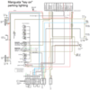
In normal operation, all the power for the lighting comes directly from the key. When the key is in RUN;

    - power from the key goes directly to F12, enabling the brake lights, the alternator lamp, and the directional turn signals.

   - when the lights toggle switch (1st position) is flipped up, power is enabled to F3, which turns on the running lights markers (up 6 for Euro cars, 8 for US cars), and the dash lighting. Gauge brightness is thru the rheostat, the #2 toggle, but the ring lighting at the cigarette lighter (and the indicator lamp in the Tach) are not affected by the rheostat.

  And now, you can use the trunk light

mangusta parking light diagram

Attachments

Images (1)
  • mangusta parking light diagram
Last edited by leea

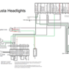
Lastly, the headlights. Then only question on behavior is whether the High/Low control is stalk forward or stalk center...Note that in "flash" mode, the power is sourced from F7, otherwise the headlight power comes from the key (and thru the 1st position toggle switch). The Carello relay (mounted near the steering column) acts as a bridge to enable both High and Low beams---this "rele per fari allo jodio, solo per il tipo Curopa" (relay for iodine headlights) was only for Europe--(and maybe since US cars would have shipped with sealed beams, not a Halogen bulb...thanks for Project Binky (#26?) explaining that the heat of a halogen with High/low beam simultaneously is a problem).

The headlamp circuit is simple, but not ideal; Esp, the length of the circuit (wiring to the key, thru the switches and then back to the fuse box, before routing back to the front of the car) probably means a bit of voltage drop before the lamp...And the simplicity of using the ignition switch means that basically all electrical power needed to run the car is perpetually sourced thru that one little point... So a possibility for those concerned about wearing out their Marelli switch is to install a relay next to the fuse box, sourcing power from the F9/battery junction and using the wire from the High and Low beam indicator stalk as a control for relays (instead of actually pulling big current thru the switch). If you drive perpetually with your lights on, could be worth considering (and likely you would be able to put a couple micro-relays in the area, without needing to cut a single wire...) and not jeopardize the ignition circuit of the car--Lee

mangusta headlights diagram

Attachments

Images (1)
  • mangusta headlights diagram
Last edited by leea

OK, I REALLY missed the boat on this one for the most part.....was busy moving after 35-ish years in one place.....  Moving "Waldo's Garage" was no picnic nor was "new house refurb" before we could move in....then of course where was "move out refurb" after 35 years!!!

SO, I wanted to say, FANTASTIC effort on the parts of all that made this drawing happen!     I recall working from a copy of a copy of a copy, that I know I distributed to many over the years.....and it was the ONLY (very early) version that I have ever seen, noting that the missing AC/Headlamp/Dash stuff Carello relays do now appear at the top of the new drawing!    The technical Italian--> English technical don't translate easily either!

I recall YEARS ago, in the last millennium (love saying that....!)  one of our PCNC members spoke/read Italian and was kind enough to translate the fuse block cover labeling for me!   Had no CLUE what I was trying to find/look for when troubleshooting.    Just this translation helped a lot! 

This new drawing should go a LONG way to helping present and future Goose owners/rebuilders to come!

All should take a bow!
Ciao!
Steve

where can i see this new mangusta wiring diagram? Gerald McGlothin  928 853 0473    geraldmcglothin@yahoo.com
On Friday, July 22, 2022 at 01:17:02 PM MST, The De Tomaso Forums <alerts@crowdstack.com> wrote:

[New Reply] Seeking Comments Regarding Our New Mangusta Wiring Diagram
| == To reply by email, write above this line. == |
|
New Reply By mangusta
|
| Seeking Comments Regarding Our New Mangusta Wiring DiagramReply by mangusta
OK, I REALLY missed the boat on this one for the most part.....was busy moving after 35-ish years in one place.....  Moving "Waldo's Garage" was no picnic nor was "new house refurb" before we could move in....then of course where was "move out refurb" after 35 years!!!

SO, I wanted to say, FANTASTIC effort on the parts of all that made this drawing happen!     I recall working from a copy of a copy of a copy, that I know I distributed to many over the years.....and it was the ONLY (very early) version that I have ever seen, noting that the missing AC/Headlamp/Dash stuff Carello relays do now appear at the top of the new drawing!    The technical Italian--> English technical don't translate easily either!

I recall YEARS ago, in the last millennium (love saying that....!)  one of our PCNC members spoke/read Italian and was kind enough to translate the fuse block cover labeling for me!   Had no CLUE what I was trying to find/look for when troubleshooting.    Just this translation helped a lot! 

This new drawing should go a LONG way to helping present and future Goose owners/rebuilders to come!

All should take a bow!
Ciao!
Steve

[ View Reply ]
|
| The De Tomaso Forums
You received this based on your notification settings. You can adjust your settings or unsubscribe anytime.
|

Guys,

Still working a bit with a shop rewiring from scratch.   The are trying to require with Jon's new "goose block" and also looking at the new schematic.

Of question, is the #30 pink wire circuit from the switch......      That circuit originates at the battery, with ties into the alternator and the amp gauge.

Is the amp gauge hot or operable at all times?    I recall wiring in an aftermarket gauge in an old Chevy and I had it hot 100% of the time and it proceeded to drain my battery on a regular basis, until I change something.......perhaps it was a volt meter.....way too many decades ago!!!!!!    Not sure if this is a big deal or not...... but would like to understand.

I also don't recall my radio being on with key off.......  This may have been changed by original radio installer or myself.....also CRS here!!!

The rest of the "100% live fuses" like windows, courtesy lamps, etc seem good.

What is the arrangement of this pink wire at the rear of the car????   There is a 2 on the schematic and I don't quite understand this, right before it goes to a split(?) black wire off to the alternator and the ammeter......   Where is this splice and what does the 2 mean???

Thanks in advance!
Steve

Hi Steve!  Not sure how to answer your first questions, but I do know that the junction between the large black and large pink wires (which are indicated by the '2' in the schematic) is hidden inside the left rocker "tunnel", visible only once you pull the front harness section 1-2 feet back into the engine compartment.  IIRC the black wire a contiguous strand, running from the alternator to the ammeter, and the two pinks are grafted on and the resulting solder joint was wrapped in electrical tape.  Not exactly elegant so maybe that's why the whole things was hidden in the rocker?

Another detail worth mentioning....you probably noticed that the 2 pinks feed the bus that ties fuse 'inputs' 4 through 9 together, not fuse #9 specifically.  So they can attach on any available tab on that bus.  Here is how it worked out on a converted Pantera box on 8MA1010.  Pretty sure the inputs are correct but haven't smoke tested anything yet!

Final note...a Mangusta box has a tab on Fuse 'input' #1, but the Pantera didn't.  No need to add one there since it wasn't used anyway

Attachments

Images (1)
  • Fuse box rear
Last edited by nate

Add Reply

Post
×
×
×
×
Link copied to your clipboard.
×