

Thanks for sharing. First pictures I have seen. In So. Calif didn't see a thing.
Orange California with welding mask,😎

Attachments
Images (1)


Did you drive the TVR…??
I did…. Primarily because our host knew the Russian Oligarch who bought the TVR Engineering Corporation after Peter Wheeler sold it in the 1990’s…
But make no mistake…. This was a Southern Arizona Pantera Club event!
It was a great trip!
The TVR could always be next to my Pantera! And the Jensen too! What a great combo!👍👍👍
let's see more pics of that TVR. Please.
Nice…. More TVR fans here…!!!!!! 👍👍👍
Yes, I own à 1996 Griffith 500.
Le dim. 28 avr. 2024, 17:44, The De Tomaso Forums <alerts@crowdstack.com> a
écrit :
Le dim. 28 avr. 2024, 17:44, The De Tomaso Forums <alerts@crowdstack.com> a
écrit :
")


")
nice looking car!
Sweet…🍒🍭🍩
So Mr. LeMans850i is making me feel bad with his unrelenting progress, therefore I had to jump into another "upgrade". I decided to install a Pedal Extender (Amerisport) and while I was at it, machine my pedal assembly for needle bearings installation on the main shaft (4x), clutch effort reduction assembly (3x) and accelerator pedal (2x).
I got all the needle bearing specs from Rene4406, and tips on how to implement it.
I will be using the mills at Pima Community College as an "Independent Project" (MAC296) to do the machining.
I got the pedal box removed and disassembled today.
")
")
")
Attachments
Images (3)
")
")
")
Couple of Tricks for Disassembly:
(NOTE: The pedal box CAN be removed with the clutch linkage connected without cutting a notch in the pedal box...)
1. Get in the car, take out the front driver's seat, and take off / loosen everything you can from underneath first. Getting rid of all the braces, accelerator pedal, etc. gives you more access.
2. (Lemans850 Tip) Use a zip tie to compress / restrain the coil springs so the pedals don't keep flying forward.
3. Lots of 2-Man jobs on this one. Thanks to Mrs. Rocky for not complaining about unscrewing nuts while I cursed and held wrenches under the steering wheel.
4. The real secret to the removal of the pedal assembly is to have the clutch pedal and associated linkage in the position it would be if the clutch was fully depressed. That brings it into a compact state and gives you the 0.5mm you need to slip the assembly out of the pedal box.
Rocky
PS> Another note.... the need for this is kind of a crapshoot, because you can't really be sure the needle bearing upgrade is needed from a casual observation. Of course I was worried about my linkage being "wallowed out", as I have seen reported by others. But when I took my linkage apart, everything was fairly greasy, and the linkage was in good shape. But if you are "in for a dime, you are in for a dollar"*!
* From Marlin's thread....
Here's a picture I saw of an effort reduction piece that needs help - and wear in this area reduces the throw on your clutch slave cylinder!

Attachments
Images (1)
@rocky posted:Couple of Tricks for Disassembly:
(NOTE: The pedal box CAN be removed with the clutch linkage connected without cutting a notch in the pedal box...)
1. Get in the car, take out the front driver's seat, and take off / loosen everything you can from underneath first. Getting rid of all the braces, accelerator pedal, etc. gives you more access.
2. (Lemans850 Tip) use a zip tie to compress / restrain the coil springs so the pedals don't keep flying forward.
3. Lots of 2-Man jobs on this one. Thanks to Mrs. Rocky for not complaining about unscrewing nuts while I cursed and held wrenches under the steering wheel.
4. The real secret to the removal of the pedal assembly is to have the clutch pedal and associated linkage in the position it would be if the clutch was fully depressed. That brings it into a compact state and gives you the 0.5mm you need to slip the assembly out of the pedal box.
Rocky
Very very good!!!👍 Bring on the pictures!
My wife always says I have a bad influence!!! 😜


By far, not as bad as yours, but I got one of those too…

but with return springs zip tight, linkage, relaxed, and turning the pin 90° it came out!
The new Fork on the clutch master cylinder is just a pressed steel part while the original one was a machined part… I couldn’t save the Machined part - sadly!
Attachments
Images (1)


Making a little more progress…
1) Bushings pushed out of the pedal assembly… all parts ready for machining.
2) I’m going with a “straight” return spring to my clutch (instead of spending $35 on one that will break in 25K miles), so I drilled a hole in the clutch pedal.
3) Replaced the front length of vacuum line to the brake booster. Line is 12mm ID, you need about 1 1/2’ of it. It is available at any VW supply store!
I guess the old “Aeroquip” line was from a PO upgrade, I’d be surprised if they used that kind of tubing originally in Italy!
It was hard as a rock, and crumbly at the ends!
Rocky
Attachments
Images (3)
Gonna be nice to just hang this spring in once everything is back assembled!
brake pedal the same?
No, I’m going to “roll the bones”, and stick with my unbroken brake pedal spring, but…. It is probably good insurance to “pre-drill” the brake pedal, as well.
This will guarantee the brake pedal spring never breaks!
@rocky posted:No, I’m going to “roll the bones”, and stick with my unbroken brake pedal spring, but…. It is probably good insurance to “pre-drill” the brake pedal, as well.
This will guarantee the brake pedal spring never breaks!
I wish that logic really works… I carry a crank and pistons and a clutch with me… 🤪


I am also replacing my passenger door handle tub with one from PI Motorsports. I took Tsolo's advice in his thread here, and fabricated a "spring pressure diffuser" for the Hall Pantera door handle spring. It came out good.
Hall door handle springs? | The De Tomaso Forums (infopop.cc)
Now all I have to do is find the three screws that hold the lock barrel in place, that I lost in my garage somewhere!


Attachments
Images (2)

Got these surplus M6 x1.0 nut plates installed…. Very cool. These are to securely (re)attach the door handle. One was stripped out…
The plastic inserts in the door were hard as rocks…
NOTE: You only need two (per door), the fixture on the top forward part of the armrest is rigidly attached to the door metal. BUT… the long M6 - 1.0 machine screws fit the stock attachment as well!


Attachments
Images (2)
Rocky, Looks like a good upgrade. What Surplus did you find them? Any left? Thanks, Larry
They’re from a little store in Tucson, I think somehow they have a connection to Davis-Monthan AFB and/or The Boneyard (a.k.a. AAMARG).
I believe McMaster-Carr carries something similar.
I used this:

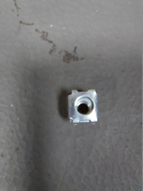

These are 6x100 metric spring captive nuts which correspond exactly to the square holes in the door, they are installed in 5 seconds and obviously the 6 x 100 screws can be purchased in any hardware store in Europe.
They are for sale on Ebay: https://www.ebay.com/itm/15597...tkp%3ABk9SR7Km-euBZA
Maybe the same thing exists in 1/4''?
Very cool.
They use those captive nuts in electronics racks to mount rack mount electronic equipment!
Great solution!
I've had these nuts for a long time but I remember actually getting them from an electronics rack ![]()
Got more machining done on my pedal assembly. Did the clutch pedal cross shaft for the 12mm needle bearing, and drilled out the main holes for the 26mm cross shaft bearings to 1”.
Fixturing and alignment were the main challenge.
The cross shaft was easiest, we had a collet clamp of the correct size we mounted to the mill table.

The setup of the pedal bracket assembly and truing it up was the hard part. We could only drill two of the four holes at a time (due to the length of our tooling), and then had to flip the piece over.
We did find that the machined surfaces on the “ears” were all true to each other, and so setup for drilling the second pair of holes was eased by using a 1-2-3 block at the bottom of the part for alignment on the machined surface.
I don’t have any pictures of our setup for the second pair of holes, but I assure you, the second half of the operation took about 1/4 the time as the setup for the first pair!

We have a 26mm reamer that is long enough to “align bore” all four holes with one setup, but unfortunately our tool holder is way too long to fit in the manual mill…. So we’re working on getting the appropriate holder for the final operation. We’ll do it in the CNC machine.
But good progress was accomplished today!
Rocky
Attachments
Images (2)
Progress!!! 👍👍
More progress…. Got the passenger door reassembled, replacing the bucket.
The little “lock clips” from Lada Power in Moldova worked great, just needed to run the appropriate sized metric tap to match the linkage rod.
The little studs worked well to ease installation.
Rocky


Attachments
Images (2)
Following onto related thread, I temporally installed my pedal assembly on tomorrow Kirk Evans spacer.
I am going to finish up the machining tomorrow on the pedal assembly, and will begin the reinstall soon.
I did take Steve’s advice and moved the vacuum hose forward. Considering doing the same to the clutch hardline.
Kirk Evans sent me a threaded throttle cable extender…. Need to test fit that as well.
Rocky

Attachments
Images (1)
Add Reply
Sign In To Reply