
I have been threatening to do a write-up on my build for a while. I see all these great threads, for example the ones by Rob B., Kirk Evans, and and others detailing extensive, very high quality work being done to their cars.

My skills are not as tremendous, but I have the help and assistance of a an expert Pantera enthusiast and Hot Rodder (Wade - 4280 / Mark IV) and the resources of this board.

My project started as a new motor build, with upgraded performance goals. I wanted to "freshen up" the stock engine, and give the car more power, but retain the classic, stock lines.

Once the motor was built (about Feb., 2014), I pulled the original engine. That was when the scope of the project really changed. Things I found, and upgrades I needed boosted the scope beyond what I was expecting, but it all needed to be done. If you are in for a dime, you are in for a dollar!

My wife (first and only) was surprised by the workload, but what can be done?

I am far along, and I can see the light at the end of the tunnel. Hope you enjoy the pictures, and the details of my build progression.

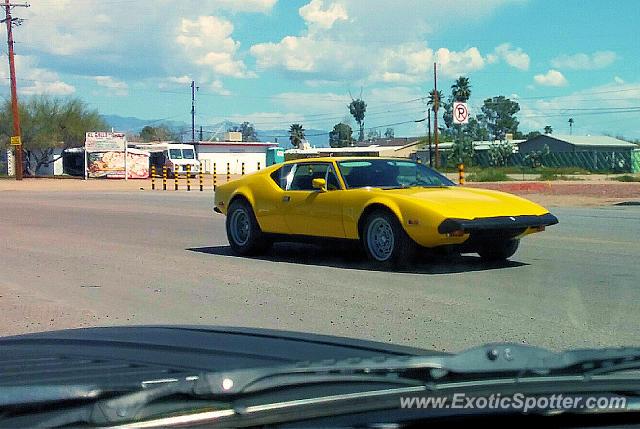
Here's my car before the resto. I'll try and shrink the pictures in future posts.


Last edited {1}
Original Post

Replies sorted oldest to newest

The engine is a basic 351C, sonic tested, and bored .030 over. It is designed (hopefully) for reliability / durability, oil control, and additional power. I am working to make it "tractable" on the street. It is also intended to run on pump gas.

Significant effort went into achieving these goals.

It will be normally aspirated with a 735 CFM Holley (modified for "4 corner idle") and an Edelbrock Performer dual plane manifold.

Oil control scheme includes lifter bore bushings (Wydendorf Tooling and Oilite bushings, T. Meyer restrictive cam bearing set, appropriate plugs in oiling passage to cam, and a drilled "oil squirter" on the gallery plug by the distributor gear). The squirter directs a stream of oil onto the cam / distributor gear interface. Additionally, the oil pump and passages into the main engine feed were ported to reduce restriction in the pickup and feed circuit.

Heads were ported to improve flow. Bench flow data is showing 288 CFM / 190 CFM at .600 lift.

I plan to run a standard Duraspark II electronic ignition, with an eCoil. Most of the electrics will be close to stock with the remote solenoid, and external voltage regulator.

Wade fabbed up a bracket for the AC compressor and alternator. This supports a future "flat bulkhead conversion".

We will be running a Sanden AC compressor inboard, and the Ford alternator outboard. Idlers / tensioner modifications were needed.

Part Number / Statistics
Block - DOAE-L Casting (2 Bolt Mains)
4V Heads (Open Chamber)

TRW Domed High Compression Pistons - L2348 .030 Over
Coated Performance Rings
T. Meyer Oil Control Cam Bearings
Crank - Oil Holes Chamfered, Bearings .010 Under

Pioneer Harmonic Balancer
Rollmaster CS3091 Timing Chain
ARP 154-3604 - ARP Cylinder Head Bolt Kits

Bullet Cam - Hydraulic Roller (See GP Hydraulic Cam in "Sticky #3)
Matching Hydraulic Roller Lifters; Morel
SS Single Piece Valves
Matching Valve Springs
10° Steel Retainers
Teflon Seals
Comp Cams Ultra Pro Magnum™ Roller Rocker Arms: Ford; 7/16" Stud, 1.73 Ratio (1830-16)
Guide Plates, 351C
5/16" Heavy Wall Pushrods
Rocker Studs, 7/16"

Melling 84A Oil Pump

FelPro Gasket Set - 31781 (Head Gasket 8347 PT-1)
ROM Turkey Pan Intake Manifold Gasket

New Steel Flywheel
Centerforce Pantera Clutch and Pressure Plate
McLeod Pantera Throw-out Bearing

Avaid 10 Quart Oil Pan
New Pantera Motor mounts

Robertshaw 333 Thermostat
Stewart Racing EMP-16143 Water Pump
IPSCO Tensioner

Carter M6882 Fuel Pump

Spark Plugs Modified for Extra Sparkage

Ford Gen 1 Alternator Updated for 80 A Output
Sanden Rotary AC Compressor


I'll post more pictures once I get them organized.

Rocky
Last edited by rocky
Engine Build Pix....

Original "New to Me" Block:


Cleaned Up:


Lifter Bore Bushing Install:


Rotating Assembly Integrated:


Heads Prepped:


Oil Pump Work:


Engine Home from Build - Ready to Just "Plunk In":


Ready to pull out the old one!

All the detail work on the lifter bores, heads and oil pump was performed by 4280/Mark IV in his shop. I was merely the scrub-nurse.

Rocky
Last edited by rocky
Engine Bay Cleanup and Nightmare....

Did you ever see things that you knew were wrong, but hoped that "your eyes were deceiving you", or "maybe it's supposed to be like that"?

I saw a crazy coating / filling on the bottom of my swirl tank. It looked really funky, but I thought (hoped) it was "supposed to be like that".

I also saw small area of corrosion coming through on the passenger upright. "Maybe it wasn't a big deal", I thought.

Once I pulled the motor - It was apparently obvious. The swirl tank had leaked early in the car's life, and the first owner had the swirl tank patched / soldered / epoxied / etc. The tanks were a mess.

My belief is that fluid was dripping down into the passenger side upright, and corrosion had occurred. It looks like this had happened a long time ago, but the damage had been done. There were no other areas like this - it seemed to be limited to the passenger side upright. This exact situation was described recently in a Bosswrench post.

I tried to deny it to myself, but once the motor was out, I couldn't. The structure (upright) had to be fixed.

Prior to the engine pull I had been working on scraping the stock undercoating. I struggled with the options of using a truck bedliner (like the Banzai Pantera), or paint. I finally decided on Ford Grabber Yellow.

Again - I didn't realize the amount of work that was entailed in an engine bay prep. In fact, with regard to bodywork, there is never a point in which you can say..... "It's 100% done". You can always do more, scuff more, clean more, etc. I have to say, we did a good job of prep, and I believe I have a good foundation for the future.

I did not try and make the bay 100% pristine. Dimples / imperfections from the factory build remain. If someone wants to take it back to stock with the factory bedliner, they can have at it. I think my engine will look good inside the new, cleaned up engine bay.

Stand by for more pictures once I get them organized.

OBTW: Did I mention that my buddy 4820 / Mark IV has the mad skillz needed to execute such a repair project? Thank Gawd!
Last edited by rocky
Stand by for additional upgrades, including:

Valence Repair
Jacking Point / Structural Upgrade in Rear Cross Member
Engine Bay Brace Weld Cleanup
Bay Paint
- Inner Bay is Black
- Outer Bay is "Grabber Yellow"
Bulkhead Cover Opening Repair and Nut Plate Alignment
Flat Bulkhead Modification
Stainless Steel Bulkhead Covers and Insulation
Reconstruct Rear Upright Bushings
Removable Bay Brace & E-Brake Bracket
Hardline from Radiator to Swirl Tank
New Swirl and Overflow Tanks with Improved Cooling Design

Lots of work was done while the "Big Cat" was in the shop. My goal was to get it in and out in record time. I believe the car spent about 3 weeks away from my house, and honestly, the volume of work accomplished during that time was eye-watering.

Stand by for more pictures...
Last edited by rocky
Front Valence Repair:

The inside of the radiator cavity was in good shape, but the bottom of the valence had seen it's share of impacts over the life of the car.

There had been some work previously done to make it look OK, but close inspection revealed that it was really a mess. Once we got into it, you could see that the metal had been pulled back out with a slide hammer ("the bane of artists in sheet metal"), and a lot of body filler had been used to repair the damage.

Wade fabricated a bottom panel, and reworked the existing metal to rebuild the "chin", like a surgeon resculpting the chin of a 42 year old Kardashian.

I think the results are spectacular.


While we were up front, we did a bunch of minor work to the radiator, reseal, clean, paint, and tie off the wiring.

We also added a hardline from the front to the rear of the car, that will provide an automatic air bleed to prevent air from being trapped in the radiator.
Last edited by rocky
Rear Jack Point / Structure Reinforcement:

This one is in honor of Rob B. My rear cross member had taken a couple of hits back in the day, so we decided to open up the original box and straighten it out. This allowed us to add some improved structure in there.

You can see in the picture that the frame is sound. A 1/4" thick steel extrusion fit into the space like a glove, and is unnoticeable in the final product.

This gives me a robust jack point for the rear of the car.

Did I mention all this fabrication work was done by Wade (4280 / Mark IV)?


Last edited by rocky
Thanks, guys, appreciate the compliments. This has been a long journey, and I'm happy to show off the results. Garth, not sure I will make it out that far this year, but who knows! I've gotta get it running, first!

Painting of the Bay....

Shot the bay with three colors / textures. Yellow for the main bay area, black inside the motor compartment, and a bedliner type substance on the outside of the frame, and inside the wheel wells.

It came out very nice.


Also powdercoated the rear suspension, and some of the accessory pieces (Electrical panels, tank holders, pulley).


Last edited by rocky
Stainless Steel Firewall Covers....

We sprayed Bedliner, then I installed the original firewall insulation, then an additional layer of foil-backed fibrous insulation.

Finally, installed the stainless Steel Bulkhead Panels. "Nut-Serts" were set into the original firewall. The machine screws on the corners press the steel against the insulation to avoid any potential for vibration.

Nutserts in the steel also hold the tank cover on. More nutserts and P-clamps will be used to secure the engine bay wiring harness (which is just now reaching completion).


I'll get a picture soon with the tank cover on.

Rocky
Last edited by rocky
I don't believe so. Mine just had a fiber insulation glued onto the bulkhead.

It seemed like the top (outside) layer had a hard coating on the top.

I think the same material is used inside the passenger compartment, as well (behind the upholstered firewall cover).

Did I mention who cut out, and formed the SS panels? I am proud to say I did cut out the cardboard template that was used in their design. They really fit great. Thanks Wade!

Rocky
Last edited by rocky
Another Unexpected Setback... Overcome

When I bought my car, the PO had told me about the rear bearing replacement in the uprights, and went to great lengths to describe the custom socket fabricated to do the job.

Prior to disassembly of the suspension I did a "wheel wiggle" test, and found some play in one side of the car.

Upon further investigation, it turned out the play was not in the wheel bearing, but in the bushings in the bottom of the lower upright. Here's a good thread with additional information on the bushing design:

Stubborn Suspension Bushing

We were in a rush to get the suspension reassembled, so Wade (always up for a challenge) suggested that he fabricate the bronze bushings. The bushings are standard metric size - the id/od/length are mm dimensions 24 x 27 x 29 long.


Here's a set of pictures. In the first, you can see (sort of) one of the offending bushings - it had to be cut to removed. The rest is the fabrication and assembly. Lest you be concerned, all bushings were reconstructed and replaced.

I had purchased (on a whim) two upright shafts (from Mayberry Pantera), and a complete bushing / ball joint kit (Maseratisource). All new parts were used in the reassembly.


Another major project successfully completed!

Rocky
Last edited by rocky
Next project -- Removable Chassis Brace and E-Brake Bracket

This one was of smaller scope.

While we were in there prepping the bay, and cutting on sheet metal, we decided it would be smart to make the bay obstructions removable.

A Sawz-All cut the bay brace, and a drill and chisel cut the e-brake bracket loose.

The Main Bay Brace required precision measurement and fabrication. These slip right in, and the brace is retained by the two forward suspension bolts.

While the e-brake bracket was of a slightly lighter construction, it required a stringer across the bay to give it more structure.

Steel Nutserts were put into the frame channel on both sides to retain things. It's plenty strong.

We chose to use the original ebrake bracket to reduce the amount of detail fabrication. All it really needed was a little more structure to hold it in vs. the force that will be applied by the lever and cable mechanism....

See for yourself. Sorry, the bay is still a little messy.

Bay Brace:


Emergency Brake


Last edited by rocky
Did someone say "Cooling Tanks"?

This was more of a challenge. My tanks were shot. The swirl tank had failed in the early days of the car, and had been repaired. Cutting it open and looking inside showed it to be unserviceable. The same situation was found on the overflow tank. It was held together inside only by the big chunks of rust.

I half-heartedly looked for some used ones (which of course needed to be in pristine condition). None could be found.

In consult with a master mechanic and fabricator, we decided on an approach that would cause the system to actively draw air from the radiator and the swirl tank into the overflow, by running it at a vacuum. It looks pretty slick. I believe the design was described in one of Carroll Smith's (manager of the Shelby Racing Team) engineering designs.

Here's the pictures. The two fittings on the tall overflow tank are the inputs (one from the top of the swirl tank, and one from the radiatior via hardline). The lower fitting is suction from the waterpump.

The overflow tank is under suction from the water pump, and will actively draw any air from the upper corner of the radiator.

The rest of the cooling system is standard, except the pressure cap has been moved to the overflow tank.

Here's what the tanks look like:


Getting tired of this yet?

More to come!
Last edited by rocky
While there is a lot more work to display, such as:

Safety Wired ZF
Centerforce Dual Friction Clutch
AC / Alternator Offset Mount

I completed with my interior bay wiring.

I had a little scare when I found that I only had 100 Ohms to ground on my alternator "main feed" with the alternator disconnected, but after some troubleshooting and test, first with low voltage, then with standard 12V, it appears that all is well.

My car has had very little electrical issues (up to now, keep fingers crossed).

I spent a lot of time dressing the harnesses. My sheathing didn't always fit as good as I would like, and I probably need a little more service loops in some area, but everything is secure.

Let me know what you think.


Last edited by rocky
Thanks, Garth -

That's a Duraspark II ignition module.

That one is a "Eichlin" (NAPA) version, but they are all about the same - from outward appearances.

Engine should be going in shortly - possibly this weekend, but if not, but the end of the week, certainly.

Just to whet your appetite, here's a picture of the "outboarded" Compressor / Alternator setup that Wade (4280 / Mark IV) fabbed up.... Still needs a little adjustment work on the Alternator Tensioning system (minor challenge).


Rocky

Attachments

Images (1)
  • 05-16-2014_(11)_(Small)
Minor Setback..

My cool Stewart Stage 1 351C Water Pump Impeller was jacked up (Rubbing on Timing Chain Cover) - straight out of the box!

You can see where it was touching the timing chain cover in the picture above.

Summit Racing is shipping a replacement Monday... Good customer service by them, I must say.

Rocky
You guys are very observant! The relay is the one that George recommends in his Duraspark II schematic, to reduce the current load through the ignition. Search on Duraspark II and you will find the schematic.

There is also a 15A blade fuse in there as well.

The switch is my secret ignition disable.

Don't tell anyone!

Rocky
glad others asked those questions as I was stumped about the items! (sort of guess though)

as for the "kill" switch, that is pretty well hiden as one would need a wrench set to remove firewall bump to access. I recall having a similar switch there, but it was something about setting the dual points dwell.

From the regulator, can I assume you are running the original design altenator, or is a regulator needed with updated altenators also?

And is the shown arrangement of belt driven accesories for the reduce bump firewall?
With regard to the Voltage Regulator - I am still using my Ford 1G (3 Wire) alternator. I took it to one of the local shops (Luna Industries 520.792.3080) in Tucson, and had it rebuilt. It tested at 78A output after the rebuild. The rebuild, which put better "guts" in the stock case cost $92. They replaced bearings, brushes, rotor, rectifier and field coils.

I saw no advantage (really) to converting to a 1 wire alternator, due to the inconvenience of figuring out how to rewire things. I can't remember now, but there was another issue with going to a single wire alternator - maybe it had something to do with the charge / discharge light?

The belt driven accessories are set up like that for the flat firewall cover, and the (future) flatter bulkhead. It won't be 100% flat, but enough to give my wife about 3 more inches of seat adjustment.

Rocky
You may have seen my previous thread about poking around inside of my ZF... Things inside there were worse than I thought, but it seems that I caught the problem just in time....

Am I the Luckiest Guy in the World?

Anyway -

Here are the remainder of the pictures of the ZF Safety Wire project. Actually, once the ZF differential case was opened up, it was pretty straightforward. We didn't get into the gear sets.

One thing that is hard to find in one place are all the torque values. Here's a good resource - but it doesn't have them all. When you do this, you can give Lloyd, Les, Ron, or Dennis a call - they know all this stuff off the top of their heads...

Auger Resources - Pantera Information (ZF Transaxle Page)

Thanks again to Wade who gave me 1) a hand, and 2) confidence.... and I quote: "I've fixed Volkswagen Transaxles before.. Can't be all that much different than those things!"

Here's the pictures:

Nicely Painted Spicer Half-Shaft:


Axle Housings & Axles:


Carrier and Differential:


Note Install Date on Ring Gear: 22.12.1972


Pinion and ID Data:


Wired Up Ring Gear. Note my poor "Low Impact Hammer" in the back...


Transaxle Installed:


Close-Up of Degreed Flywheel:


Another MAJOR project behind me.

Rocky
Last edited by rocky
Couple of Misc. Photos to get caught up...

Still waiting on my water pump replacement from Summit. Engine is still sitting on the floor of the garage, but is almost ready to drop in.

Gas Tank - Cleaned and Painted


ZF - I can't stop looking at it!


Clutch Install:


Powdercoated Electrical Panel:

Coil Bracket came from a "generic" Ford Car and was cut to fit the panel (by Wade, of course!).


Pioneer Balancer & Powdercoated Pulley:


AC & Alternator Mount Adapter on Stock Bracket:


Rear View of Compressor & Alternator:


Rocky
Last edited by rocky
As I build this thread, I realize how much I owe to my mentor and friend, Wade (4280 / Mark IV).

From the start of my Pantera experience, he has been happy to give me a hand, first with carburetor and distributor advice, and improvement, and then with spectacular fabrication work on both the body and the engine.

Wade has really upgraded this car in one sweeping pass. Some improvements have been required (rust in the upright, ZF Safety Wire), many are to maximize performance (Ported Heads and Manifold, Carburetor work), and others are just for fun (engine build, bay paint).

I feel that in this build, the whole will be far bigger than the sum of the parts.

I am really looking forward to getting the car back on the road, and I owe Wade (4280 / Mark IV) a big "Thank You"! (And maybe a scotch or two!)

Rocky

PS: Best wishes to all as you head to the Fun Rally - I wish I was going!
Answer's to JFB and Rodney (UFO-LOW).

The edging material is from Elliot Electronics in Tucson (but we both suspect it can be obtained at any well stocked electronics supply store - maybe even Radio Shack), it is designed for irregular holes to prevent chaffing.

JFB - with regards to the bushings, they are a standard metric size - the id/od/length are mm dimensions 24 x 27 x 29 long.

You may be able to pick them up at a standard bushing house....
Couple of Updates...

Motor goes in tomorrow (that's the plan, anyway).

Here's the fuel system (pump & lines)....


Newly ported Edelbrock Performer Intake Manifold.

There was a lot of material in there that was removed. The porting was done to match the outline of the gasket, which had been previously verified to be highly representative of the port size and shape.

Don't want my heads to be restricted by the manifold that feeds it!


OK - Back to work!

Rocky
Last edited by rocky
Engine Install Day! One giant leap forward for my project!

What a feeling of progress!

Wade came by and we knocked out a big chunk of the "endgame" work. We got the motor checked out, and installed. Lots of little items that had been on hold were accomplished. Here's some highlights....

Motor Mounts and Formed Heater Hoses...

There is a shielded sleeve for my heater control valve. This valve will be operating in the engine bay, vs. in the cockpit. The formed hoses are the shizzle for the Pantera application.

The brown wire will mount to the oil temp sender in the front of my Avaid 10 Qt oil pan. The plan is to wire it through the "spare" switch on the dash, so I can check oil or water temp with the flip of a switch.


Oil Pressure Verification - SUCCESS!

A broken distributor and a drill makes a cool oil pump driver. A spare oil pressure gauge tells the tale. At idle speed (actually, well below it) the motor was registering 25-30 psi. At slightly higher rpm, the oil pressure relief was opening at 75-80 psi. Just as we had planned.


An Old Racer's Trick - Right Steve?

These petcocks on both sides of the block let you drain down the coolant when needed. This allows you to make much less of a huge mess.

I would venture to say that these petcocks add about 5-6% more cowbell to my engine build (each!).


In She Goes...

Not much more to say here...


In The Bay!

Still have to do electrical checks, ZF Fill, coolant fill, and some work is still needed on the exhaust, Bulkhead Cover (alternator clearance) and lots of other little stuff. But the day will soon arrive for the break-in and then... the sky is the limit.


Rocky
Last edited by rocky
Cool Trick - When You Drop a Nut inside a Non-Ferrous surface... (Like in the Motor Mount)


A magnet ball inside a baggie can get in where your fingers can not.

I am sure this would work in a magnetic area as well, you just have to figure out a way to get the magnet into the area where the missing hardware is located.

Attachments

Images (1)
  • 05-24-2014_(28)_(Medium)
* * UPDATE * * Cable Controlled Heater Valve

I found the cable controlled heater valve that recirculates to the pump when the valve is in the closed position. This valve cost about $18 at the local parts store.

This valve will be going in the engine bay, and will eliminate flow into the cockpit when shut off. I am using a cable system from the original heater lever. We will have to fab up a little bracket / cable clamp to mount the cable, and to position the bracket in the engine bay area.


[url]=http://s1298.photobucket.com/user/Rocky_LC/media/351C%20Engine%20Build%202013/06-26-2014108Medium_zps82ad7750.jpg.html]
[/url]


[url]=http://s1298.photobucket.com/user/Rocky_LC/media/351C%20Engine%20Build%202013/06-26-2014111Medium_zps1734910d.jpg.html]
[/url]


[url]=http://s1298.photobucket.com/user/Rocky_LC/media/351C%20Engine%20Build%202013/06-26-2014110Medium_zps583cfaf4.jpg.html]
[/url]

I am removing the original valve in the front - it is VERY stiff, and just replacing it with a 90 Deg. brass elbow.

* * * Another Update - Electronic Heater Valve! * *

This is an electronic version of the one that Wade and I are working on.

Electronic Remote Heater Valve

Dave (2811) has one of these babies, as you can see in his picture (Post #2 of this thread)

Dave 2811 Remote Heater Valve


Rocky

The old valve I posted will be going back onto eBay when I get some time. It's not really what I was looking for.

Attachments

Images (1)
  • P1010007_(Medium)
Last edited by rocky
Headers -

So my car came with a set of "Big Bore" headers (at least that's what I think they are). Looking at them, they were coated, and in good shape, but when looking in the collectors, we noted significant restrictions to flow. Since we were optimizing flow in this engine build with porting of the intake manifold, intake ports in the heads, and the heads themselves, it didn't make any sense to have restriction in the exhaust.


 photo 06-17-20141Medium_zps3b9d943d.jpg~original[/IMG]        </a><BR><BR><a href= photo 06-16-20145Medium_zps83eaaf0f.jpg~original[/IMG]        </a><BR> <BR><a href= photo 06-17-20144Medium_zpsfe354a8b.jpg~original[/IMG]        </a><BR><BR>The header attachment bolts were machined with a locating boss in the bolt flange.  This allows a more positive header alignment, and helps to prevent the bolts from loosening up.  It's a little tougher to see in these pictures.<BR><BR><a href= photo IMG_1229Medium_zpsb3289aa1.jpg~original[/IMG]        </a><BR><BR><BR><a href= photo 06-17-20148Medium_zpsa943d280.jpg~original[/IMG]        </a><BR><BR>Tubing to the mufflers will be upgraded to 2-1/2
Rocky

PS. This is another example of master craftsmanship by Mark IV / 4280 - thanks, Wade for the help.
Last edited by rocky
Here is why I have been out of touch - 3 weeks in the mysterious Orient (Turkey) with the family.

Are there any Pantera owners over there?

Istanbul

 photo 05272014_Istanbul45Medium_zps248da4b2.jpg~original

Herikaya

 photo 06092014_Herikaya18Medium_zpsf1bbdfce.jpg

Cappadocia:

 photo 06032014_Cappadocia86Medium_zpse9efa9ea.jpg

Fetiye:

 photo 06052014_Fetiye21Medium_zpsa706fde6.jpg

You would not have believed the roads. We drove 3850 km (about 2400 Miles in 3 weeks).
In all that time, I only saw one cop actually enforcing speed limits. Since we lived there 16 years before, the country has developed an amazing network of roads. I wished I had my car with me. I am not kidding, it really would have been a BLAST to do 2500 miles in a Pantera over there!

 photo 06102014_Assos2Medium_zps59ff57dd.jpg

Rocky
Last edited by rocky
Compressor Bracketry - Fitment & Install

So I have finally got my compressor / alternator bracketry installed. It took a couple of "ins and outs", primarily because of the additional thickness of the extra insulation and the Stainless Steel covers on the rear firewall.

It is the same basic design as the "David Nunn" setup - his is on a Fontana Block, mine is the stock 351 Ford. Here's a link to David's Awesome motor...

Fontana block a/c compressor bracket

My setup is in the car now, and I expect it will stay in there. Things are very tight - I need to be careful of my grounding wires, my heater hoses rubbing on the idler pulley, and the alternator fan rubbing on the SS panel, but it looks like we have solved the major fitment issues, thanks to my buddy Wade (Mark IV / 4280).

Oil Temp Sender

The oil temp sender is in the front of the Avaid 10 Qt pan. It is the standard water temp sender that Neil (my PO) won at a POCA Fun Rally raffle about 6 years ago. It will be wired through the spare switch so I can check oil or water temp on the same gauge.

 photo 06-22-20141Medium_zps37f7070d.jpg

Bracketry Install

Here's some pictures.

 photo 06-22-201416Medium_zpsac801f68.jpg

 photo 06-22-201413Medium_zpse3b6d41c.jpg

 photo 06-22-201417Medium_zps26326d79.jpg

 photo 06-22-201420Medium_zps95b74070.jpg
question about your belt drive axuilarries. I can't recall how the original fit and the reason for the offset bump in the bulkhead cover.

so, to be able to reduce the bump to just over engine center line, the belt drives are places low. Is it the slope in the fire wall that allows the pulley/belt not to protrude into the passenger compartment?
Rocky what you might want to do is inserting the long Bolt that holds the Alternator from the rear side. It will be a lot of work to get that thing out if you ever need to change it. Been there done that ;-) In fact the kit I got from Kirk had a welded Nut on the rear side which I drilled the Threads out off to slide the bolt in from that side and put a Nut on the front side.
Jan
quote:
Rocky what you might want to do is inserting the long Bolt that holds the Alternator from the rear side. It will be a lot of work to get that thing out if you ever need to change it. Been there done that ;-) In fact the kit I got from Kirk had a welded Nut on the rear side which I drilled the Threads out off to slide the bolt in from that side and put a Nut on the front side.

Great idea Jan! I'll have to be sure to do that when I reinstall my engine in a few weeks.

Hey Rocky, I see you had to use washers to shim your ac/alt bracket at the block. I had to do this as well when I installed my engine last year in order to get the proper belt alignment.
Note that the picture in Post 106 is the collector BEFORE modifications to a 2 1/2" tube.

We were concerned about the flow restrictions based on the alignment of the collector. It looked pretty bad!

PS> Goodroc - I decided now is the time to make these kind of changes, so I pulled the assembly and will reverse the bolt. Thanks for the tip.

PSS> Garth - On mine, the alignment looked pretty good when I bolt the bracket right up against the engine block with the two 1/2" bolts. I just decided to fill the space in the back with washers so the bracket didn't deform when I tightened it down. But it makes sense that that spacing is there for pulley alignment. You learn something new with every post (and every time I put that bracket in and out!).

PSSS> Garth - good to hear you engine is going back in.. Did you do anything other than fix the bent pushrods/rockers?
Rocky
Last edited by rocky
Anders - I just got them at a standard parts store. I just asked the guy behind the counter to find me a pair.

I don't know if you have O'Reilly Auto Parts in your neck of the woods. I have two different hoses (one is slightly shorter than the other). Either will work - it's just the length of the straight end that is different.

Part Numbers are DAYCO 80417 & DAYCO 80418.

Here's a link to one on Amazon:

http://www.amazon.com/Dayco-80...t-Hose/dp/B000C0TE8W
Last edited by rocky
The little thing on top of the PCV valve is actually plugged (from the factory), but it allows you to remove the plug.

I am not sure why you might connect your PCV to two sources of vacuum, but that's what it seems to be.

It's nutty!

Thanks for the idea on the Spacer - I am just trying to make things look good, with minimal downtime. Now is the time to bend those tubes down before we fill them with coolant.
quote:
Garth - good to hear you engine is going back in.. Did you do anything other than fix the bent pushrods/rockers?

Replaced all valve springs with new dual valve springs - remember, one of my fancy new beehive springs broke (turned out several were out of spec so much so that I suffered coil bind situation). Had to re-machine the heads, new teflon valve guides, new valve job and additional porting to clean of the newbie mistakes made by the shop that originally ported them, and replaced all the roller rockers (Scorpion warranty replacement) because I discovered that the pushrod was contacting the underside of the rocker body at full lift. I apparently received an OLD box of Scorpion roller rockers that must have sat on the shelf for years (they were silver instead of blue). According to the warranty tech, the old rocker body doesn't have as much clearance to support their advertised lift capacity. The new blue roller rockers have much more clearance.
my thoughts on the swirl tank...
even though "thinking" about how I want my coolant is very far down on my list, I am sure I am going to do similair to swirl tank with continous venting.

I'm thinking I want the swirl elevation as low as possible but with the top just above the top of the block elbow. this is where the top of the swirl will be the high point of the block and hopefully the level in the pressure (formerly overflow) tank will also be at the top of the swirl.

Attachments

Images (1)
  • swirl_tank
Last edited by jfb05177
JF -

The setup I am using, I believe was originally developed by Carroll Smith while working the GT-40 program with another famous Carroll.

http://en.wikipedia.org/wiki/Carroll_Smith

Anyway - the large (Overflow) tank is actually under suction from the water pump. The two inflows at the top are designed to remove air from the radiator and the top of the swirl tank.

Other than that (the Overflow tank plumbing) - it is similar to your drawing.

*** Update: Here is a nice diagram of my setup, taken from one of George's detailed threads. Scroll down to the cooling system part.

GP Sticky on Cooling System Configuration


Java - I am glad you are enjoying it - I am trying to make some progress daily - Hopefully soon we will be driving!

Rocky

Attachments

Images (1)
  • Cooling_Systemx800_zps36134270-1
Last edited by rocky
quote:
posted document 'May 25, 2014 06:21 PM'


I updated the Heater Valve Info (Page 6). I would have moved it, but there was other discussion there.

Thanks JF - I figured this is a good way to show off all the stuff we are doing - hopefully, most of it won't be obvious to the casual concourse judge!

Garth - looking forward to another video!


Rocky
quote:
Originally posted by Rocky:
Anders - I just got them at a standard parts store. I just asked the guy behind the counter to find me a pair.

I don't know if you have O'Reilly Auto Parts in your neck of the woods. I have two different hoses (one is slightly shorter than the other). Either will work - it's just the length of the straight end that is different.

Part Numbers are DAYCO 80417 & DAYCO 80418.

Here's a link to one on Amazon:

http://www.amazon.com/Dayco-80...t-Hose/dp/B000C0TE8W


Thanks!! Smiler
JF -

My water pump (a Stewart Racing EMP-16143) has two fittings on the pump body. One of these goes to the bottom of the surge/overflow tank. You can see it in the pictures of the tank a few pages back (on page 3).

The heater (heat source) goes to the discharge fitting on the block and the return goes to the second water pump suction fitting on the pump body.

The valve allows circulation from the block back to the pump when the heater valve is closed. It's actually a pretty slick design.

Rocky

Detonator -

The wiring looks good because of all the new sheathing around it. Honestly, while I don't mind doing electrical work, it takes me a LONG time to do it, because I always get myself confused....

It takes me a lot longer than it should - maybe I don't do it enough!
Last edited by rocky
Continuing to make progress, albeit slowly -

Both headers are on. All wiring and electrical checks complete. All plumbing on top of the engine is done.

E-Brake is hooked up (pretty cool, note the removable bracket again) - the E-Brake mechanism required some more jockeying of the water tubes.... Heading back out to do the final adjustment and to tie the cables up and out of the way....

Next the speedo cable....


Rocky

Attachments

Images (1)
  • 07-06-2014_(5)_(Medium)
quote:
Brilliant...I think I'll use that :-)


Rob -

I wish I could claim credit for even some of these ideas and the execution on my car, but they are really Wade's (Mark IV / 4280). He is the "Leonardo da Vinci" on this project, while I am the apprentice.

But his ideas, recommendations and his execution has really been top notch. The main reason I wanted to do this thread is to showcase many of his ideas that we have implemented.

Wade has got a lot of experience with Fords, Mustangs, carburetors, and he has his own Pantera. I appreciate his suggestions of how to improve my car - everything we have done has been top-notch.

The last item to getting on the road is getting the headers and the tailpipes aligned and bolted up. Hopefully, we can start the car in less than a week.

Rocky
Heater Valve Installed!

I ran Aeroquip Teflon Hose (Stainless Steel Sheathed) from my heater control lever back into the engine bay. We ran some soft stainless steel wire from the existing Heater Lever to the engine bay mounted heater valve.

Wade fabbed up this cool heater control mechanism.

Here's pictures of the valve on the bench, and installed.

 photo 07-09-20144Medium_zps33e94c99.jpg

 photo 07-09-20146Medium_zps1cab8c7a.jpg

The hoses keep the assembly located, but I added a small tab to the valve cover bolt to add an extra layer of security.

I can't wait for winter!

Rocky
Exhaust Complete!

Wade hand-fabbed a set of ANSA (-1) Tailpipes to mate to my "Huge Bore" 2-1/2" header collectors, and to the stock ANSA Mufflers.

It was actually pretty tricky to get them to fit, because of the tight clearances between the halfshaft and the lower A-Arm. We cycled the suspension (a bunch) to verify clearance.

The only (minor) issue is the e-brake Cable, on the passenger side, it wants to lay on the tube. I believe we can solve that with a bit of cable adjustment.

Other upgrades that come with the (-1) ANSA tails include the flanges for band-clamps between the collectors and tails, and O2 sensor bungs installed about 4" forward of the mufflers.

Construction Details

Wade started with three "standard" 2-1/2" U-Bends (8" Center to center) - Here's a picture of (half of) one of them...

 photo 07-13-201424Medium_zps6e0bc18f.jpg

He carefully cut sections at the appropriate points in the bends to create the tails. Quick tack welds held the parts in place for fitting, and then it was gas-welded to complete.

I was very amazed that all except 1 joint were done with straight cuts (a chop saw) across the U-pipe. This caused all the sections to sit flush for welding.

I will let the pictures tell the tale. But first, a picture of the original ANSA tag on the stock tailpipe....

 photo 07-13-20144Medium_zps6b85a69e.jpg

 photo 07-13-20141Medium_zpsd0332f88.jpg

 photo 07-13-20146Medium_zpsae4bf50e.jpg

 photo 07-13-20143Medium_zpsa01e1807.jpg

I wish I took a picture of the finished product after welding and painting... They look spectacular. And fit just as good as they look!

Rocky
This thread has some good pictures of my "Huge Bore" Headers - these are "Big Bore" headers modified for a 2-1/2" collectors, and a Band-clamp flange on the end of each of the collectors.

Note: "Huge Bore" headers are a trademark of W-Wadeco Header Corporation, of Tucson, AZ

I thought it would be good to link this into the thread.

If you have Hall Big Bores, and you have the opportunity to look inside of your collectors, check them out. At least in two examples, it looks like there could be some (a significant?) amount of restrictions to flow at the collector end.

Header Color Question Thread

Rocky
JF -

The O2 bungs are for the break-in, Wade has a dual sensor / monitor system we will be using for the initial run.

In the near term I will probably plug them, but my goal is to find a O2 Monitor system to run in my car.

Who knows what the future may hold for the fuel/air system - but it's always good to have options....

Rocky
It's Alive...It's ALIVE!!!!

Wade, Spike and I fired up my car this afternoon. It was awesome. Now I have to figure out how to compress a 30 MByte IPhone video file to something I can post here...

Anyway - here's pictures of the new tails mounted up....

 photo 07-14-2014104Medium_zpsf96791ca.jpg

 photo 07-14-2014105Medium_zps6ee405a7.jpg

The beautiful engine bay...

 photo 07-14-2014103Medium_zpsd9b10e24.jpg

... and of course... Safety First!!

 photo 07-14-2014111Medium_zps3b5510f4.jpg

We got through the initial startup, and the infant set up issues, including.....

  • Smoky Startup
  • Flooding / Stuck Floats on both bowls (was bad / old O-Rings in the Float Adjustment Mechanism)
  • Initial Timing Adjust
  • Scary Noise at higher RPM (was actually the AC Compressor running unexpectedly)
  • Top End Inspection
  • Minor Leaks in the Cooling System
  • Full Diagnostic Check and Idle Adjust
  • Timing Refinement Adjustment
  • Back-Patting on a job well done.

    The car sounds awesome. I can't wait to drive it home!

    Thanks, Wade!

    Rocky
  • Thanks for the congratulations, all!

    The car is home from Wade's shop, and peacefully resting in my garage.

    No incidents on the ~7 mile trip home. The car ran great - Centerforce Clutch was smooth, steady temps, oil pressure good, and the engine sound was consistent.

    The tuning of my new "4 Corner Idle" carb (List 4609 Holley, 735 CFM) seems almost dialed in. The car is very well mannered in the low speed driving I have done, even idled right up my steep driveway with no issues.

    Lot's more to do, but I am back on the road!

    Whoo Hoo!

    Rocky
    Thanks Joe, Rob, John, Garth et. al. -

    I appreciate the appreciation and the views...

    I took the car to the machine shop that did the engine. The intent was to get a quick assessment of the filter and the oil from the first 10 minutes of the break-in (but mostly to show off the car).

    Clean bill of health from the filter inspectors!

    Here's a couple of little finish-out projects that were done:

    Picture showing the perfect balance in the Overflow Tank (the fluid level in the plastic tank is about 3/4") - very soon the external overflow will be removed, and after a few little squirts, the cooling level has found it's equilibrium.

     photo 07-20-20141Medium_zps7eb6326d.jpg


    Here is my spectacularly bent ZF Vent Tube. That Wade - when he does anything, it's first class!

     photo 07-20-20143Medium_zpsb64e102e.jpg

    Finally, a quick picture of my "cockpit rubber hose eliminator". By moving the heater valve into the engine bay, and replacing the valve with a standard fitting, appropriate nipples and elbows, my car now uses the minimum amount of hose in the cockpit, and the short piece required is just a straight shot. Much cheaper than buying one of those preformed 90 deg. rubber elbows!

    I know, I have a crack in my AC Drain Hose... Luckily for me, I don't have to worry about that for a while!

     photo 07-20-20145Medium_zpsf568eb14.jpg

    Rocky
    quote:
    PSSS> Garth - good to hear you engine is going back in.. Did you do anything other than fix the bent pushrods/rockers?

    Hey Rocky,

    Congrats on firing up your engine. Can't wait for your driving impressions and more video.

    I had to do the following work to mine after suffering a broken valve spring:
    • Ported heads, AGAIN - supplier shop did a very poor job
    • Surfaced the heads to assure a flat surface to mate to the block
    • Replaced valve springs with new dual springs - so long Beehive springs!
    • Cleaned up and smoothed the valve witness marks from piston
    • New 3-angle valve job
    • New Scorpion roller rockers - replaced under warranty due to contact with purshrods
    • New rings
    • Re-honed block due to scuffing on a couple cylinders
    • Polished crank because some metal bits from the breaking valve spring and subsequent rocker damage washed down into the pan and got picked up by the oil pump


    I'll hopefully have the engine reassembled by the end of this week, then all that remains is to drop it back in!
    Thanks, guys,,,

    Garth, not to make light of a bad situation, but "The Second Time is the Charm"!

    At least dropping your newly rebuilt engine into your clean, and freshened up engine bay should go really smoothly. You've had practice, and you should not encounter any surprises, that's what added a bunch of unexpected time to my build:

    - Rust in the Upright
    - Worn Bushing in the Upright Alignment Shaft
    - Rotted Cooling Tanks

    Engine Impressions:

    I am still working on a off-idle "stumble" that I've been having, so I'm not really at the point to declare victory. I have changed the accelerator pump cam position (a white cam, 19 CC per squirt), but only made the problem worse when I went from Position 2 to Position 1.

    Once I get the motor above 1500 RPM or so, it pulls well, I am happy with the performance in lower and mid range. I have not revved it above 3000 rpm yet, I am just taking things slowly.

    I do have good vacuum (about 14") / good brakes (one of my key criteria) and a good idle quality - it's not too extreme.

    More info to follow, but I have driven it every day, and it seems like we have put everything together right. That's a big relief!

    See below for info on the Cam Data.

    Rocky
    Last edited by rocky
    Thanks, George!

    I am sure you will - I look forward to a trip to the West Coast someday.

    I wanted to post up my Cam Specs and Flow Data - I will post the theoretical (Dyno2000) HP & Torque.

    The Cam came from one of George's recommendation (Sticky #3). I think the sticky that I pulled this recommendation from was modified (I can't find it anymore).

    Custom Ground Hydraulic Roller Tappet Camshaft

    Camshaft Spec:
    Grinder: Bullet Racing Cams of Olive Branch, Mississippi
    Telephone (662) 893-5670
    Engine: Ford 351 Cleveland, 4V cylinder heads
    Hydraulic roller tappet camshaft
    ----------------------------------
    Intake Lobe: #HR275/3533 (CRA)
    Intake lobe mathematic centerline = 112° ATDC
    Exhaust Lobe: # HR287/353 (CRA)
    Exhaust lobe mathematic centerline = 116° BTDC
    114° lobe separation angle (camshaft degrees)
    ---------------------------------
    Exhaust valve opening = 79.5° BBDC
    Intake valve opening = 25.5° BTDC
    53° overlap
    Exhaust valve closing = 27.5° ATDC
    Intake valve closing = 69.5° ABDC
    ---------------------------------
    275° advertised intake lobe duration
    220° intake lobe duration at 0.050"
    Intake lobe hydraulic intensity = 55
    0.611" theoretical intake valve lift (1.73 rocker ratio)
    ---------------------------------
    287° advertised exhaust lobe duration
    230° exhaust lobe duration at 0.050"
    Exhaust lobe hydraulic intensity = 57
    0.610" theoretical exhaust valve lift (1.73 rocker ratio)
    ---------------------------------

    Here's my Flow Data - measured. My heads were ported by a 351C Master Builder.

    Attachments

    Images (1)
    • Huber_351C_4V_Head_Flow_Data_001_(Medium)
    Last edited by rocky
    More work this weekend -

    Sanding on the decklid - the inside is ready for paint (satin black).

     photo 07-27-20143Medium_zps62587180.jpg

    Insulation of the bulkhead cover....

     photo 07-27-201412Medium_zps96e3d4bb.jpg

    The very cool new "hood support button" - custom machined from Delrin.... This update includes rebrazing of the support rod, and paint of the mounting point.

     photo 07-27-201427Medium_zpse115267e.jpg

    Finally - a picture of the car in front of the "Calle De Pantera" sign - I put about 125 mi on the car today..

     photo 07-27-201437Medium_zps955e45a1.jpg

    Anyway - Wade spent much of his weekend working on my carburetor. We did a pretty extensive test session with my original 4150 series carb. While we made a big improvement in the "off-idle stumble", performance between 1500 - 3000 RPM was not what was expected.

    So as a test program, Wade fabbed up the components (throttle linkage) to connect up his 700 CFM Holley / Braswell carb as a temporary evaluation system. This carb has 4-Corner Idle, and is a Double Pumper (Progressive Mechanical Secondaries).

    The car ran great with the new carb. It significantly boosted the mid-range "oomph", yet maintained the reasonable idle operations.

    More troubleshoot is needed on my existing carb, but it's really good to experience the potential in my engine.

    This week should entail a lot of masking, and a quick couple of coats of paint to the inside of the decklid.

    More pix and info to follow.

    Rocky
    Last edited by rocky
    More excitement...

    Getting ready to put the decklid on... Got all the hardware painted and ready.

    Check this out.... It hasn't been on the car for months...

    Had a neat experience... A random car pulled up in front of my house, a kid got out... "Sir, Sir, can I see your car? Is that a Pantera? WOW!"

    We had a nice visit, and he also knew of Wade's Brown and Orange Pantera (He told me there was another one in town). He plans to bring his Dad, and join us at the August Pantera Dinner this Sunday.

    The kid was pumped up about seeing the car... He even took a video of the engine running.

    Just when I was beginning to lose faith in the youth of today....

    Attachments

    Images (1)
    • 07-29-2014_(5)_(Medium)
    Last edited by rocky
    Darn it!


    In regards to the email you sent stating:
    ------------------------------------------------

    Dear Customer Care,

    Please assist with finding a tire that matches my specification:

    225/50-15 and 285/50-15 Michelin TB5

    These are for a DeTomaso Pantera, '73 with the 10" wide rims in the back (Campagnalo Magnesium Rims)

    Thanks,

    -----------------------------------------------

    We appreciate your request for Michelin tires. Unfortunately, we do not manufacture either size tires for your vehicle. Your request will be forwarded to the appropriate Marketing Group for future consideration.

    We appreciate your business and thank you for choosing Michelin.

    It is our goal to ensure that your issue has been resolved or your question answered to your satisfaction. If we can assist you further, please respond to this email or call us at 1-866-866-6605 (toll free) between 8:00AM and 8:00PM Eastern Time Monday through Friday or between 8:30AM and 4:30PM Eastern Time on Saturday.

    Sincerely,
    We had a car we restored in Scottsdale that had perfect looking Avon tires on 10 inch rims, look up 5298 in the registry to see how they look in the photos, they are,,,
    Rear: 10 x 15 GTS wheels mounted to AVON CR6-zz 295/50R/15 (DOT approved tire) acquired from Roger Krause Racing in California, where I get all my Pantera tires.
    You may not have heard about the terrible tragedy that "befell" me, when my fluorescent light fixture fell off my garage ceiling and whacked my car!

    Some dumb-a$$ (me) only put the screws into the drywall - not the rafters. You can bet they are now anchored with 4" deck screws!

    DAMMIT!

    I guess I can say I was lucky because:

    1) It did not fall right onto the center of my hood

    and

    2) Neither of the fluorescent bulbs broke!

    Nevertheless....

    OUCH!

     photo Hot_Rods9_zpsf4152642.jpg

    Luckily, I know a great guy who has a body shop (and a Pantera) who could handle the job....

    Rick P. - Duval Body and Paint - Green Valley, AZ

    Anyway - those boys went after my car....

     photo IMG_2004_zpsb34cc9b6.jpg

     photo IMG_2005_zpsec9dcaa5.jpg

     photo IMG_2007_zps3e18351e.jpg

     photo IMG_2006_zpsf8cc2e7d.jpg

    I just got some crappy cel phone pix, but it looks great....

    More pictures to follow...

     photo IMG_2011Medium_zps543201d6.jpg

     photo IMG_2010Medium_zps9170ab61.jpg

     photo IMG_2008Medium_zps868d2465.jpg

    To Rick, Ricky and the boys at DB&P - THANKS!
    Not too much new to report - I did replace my 100K mile Front Shock / Spring (a set of "Telecars") with a pair of "new to me" low mileage stock Aristons.

    This allowed me to take a series of basic suspension measurements, and inspect the effort for my upcoming project - new shocks / springs (all four corners) and new wheels / tires (first priority).

    I have a set of all the required suspension parts (rubber bushings, upper & lower ball joints and tie rod ends). Likely when I do this mod I will disassemble the suspension and get it all powdercoated (like the back).

    Here's just a single picture.

    Attachments

    Images (1)
    • 12-27-2014_(1)
    Thank You, Push, for the compliment. I agree with you (amazingly enough).

    Working on a set of 8" Campi rims to replace the 7" ones in the front.

    Toasting in the oven is complete. Stripment of the old paint is complete. Primer is complete. Hope to paint this weekend.

    Also working on the rear view mirrors, they will soon match body color.

    Attachments

    Images (1)
    • IMG_2742_(Medium)
    The Next Project - Front Suspension Upgrade

    We are working on the next project - an upgrade of my front suspension components. The goal is to replace the old parts, and add a couple additional performance and reliability features along the way.

    Main Items:

  • New Ball Joints and TREs
  • New Wheel Bearings and Seals
  • Adjustment of Brake Hose Routing
  • General Cleanup

    Performance / Reliability Features:

  • Upper Ball Joints Milled for 2* More Caster
  • W-Wadeco Camber Lock System
  • Powder Cost Suspension Parts
  • Zerks on All Ball Joints & TREs
  • Painting of all Exposed Steel

    Here's a picture to get you interested.


    Here is a slide show of the work to date. I will add more as the reassembly progresses.

    Suspension Upgrade - Slide Show

    Rocky
  • Well - to give you the honest truth, Wade (MarkIV/4280) handled that part*, but what he did was get a short height Sawz-All Blade, and cut the metal bushing housing top and bottom.

    Careful cutting (not all the way through) relieved the pressure, and the bushings were then pressed out. The cut was longitudinal along the bushing housing.

    I'll throw in a picture of one of the cut housings.

    I believe that I left out a lot of the swearing, re-fixturing, pounding, and hammering that was still required. I saw the rubber pieces, and they did not look like they came out willingly.

    Maybe Wade will post up a description of his technique.

    Rocky

    * as he handles 75-85% of my projects... Nevertheless - I am moving up in my skills qualification. I am now approved to sandblast on my own, and to do minor filing and scraping work. Oh, yes... Painting. I am authorized to do painting (rattle can only) without supervision.

    Yeah Baby!

    PS> (Seriously....) Thanks, Wade for your help on my project!!
    Last edited by rocky
    I wanted to show off my cool W-WadeCo Camber Lock System.

    Other systems had been evaluated, and are very nicely made, but the main drawback is they require drilling into the Upper A-Arm to mount the "Stop Plate". This could potentially weaken it.

    The engineering dept. at W-WadeCo came up with a simple design that uses a welded retaining ring on the upper A-Arm. The special Camber adjustment shim can then be used to lock the camber, as well as perform fine adjustment with the threaded shaft & nuts. As shown in the picture, the system is not tightened, that's why the washer is at an angle.

    Lock Brackets


    Adjustment Stop (Welded to A-Arm)


    Camber Lock Assembly


    Bushing

    Finally, JFB had a question on getting the bushings out. Here's how Wade did it..... You gotta be careful, though!


    Rocky
    Hey Rob -

    quote:
    Nice to hear you are getting sign offs accomplished. How soon do you think for the air tools...those are the fun ones..


    Getting signed off on air tools is a long, ardouous journey. I have to pass bench grinder certification first.*

    I did kind of jump the gun by using my angle grinder to fit the shocks (the Koni 30s "hats" can interfere with the shock brackets at full droop) a little prematurely.

    With regard to rotors -

    I am using vented 12.xx" (number to be filled in later) mustang rotors.

    With regard to brake pads -

    Stock calipers with Porterfield R4S (Street Compound).

    With regards to rear brakes -

    This will drive most everyone who has a dog in the fight nuts, but.....

    I am using the 1980's technique of dual, stock rear calipers. Since the rear uprights are "unisex", I just have 2 sets of calipers on each rear wheel. This is a common technique from the past, made obsolete by the relatively low cost Willwood kits available at several suppliers.

    I can lock up my rears any time I want, I keep my stock emergency brake configuration, and the price was right.

  • 4x $2.00 Bolts
  • 8x Brake pads
  • 2x $15 Braided steel brake hoses
  • $100 in rebuild kits for 4x calipers


    quote:
    The camber lock modification is slick. I like it. Royalties should be paid to you or W-WadeCo?


    Royalty checks should be submitted direct to W- WadeCo, care of me.... PM me and Ill send you the address! Cool


    Rocky

    * Note - I am teasing my friend and mentor (Wade) about all this. I am sure he would be perfectly willing to let me take the next step -when ever I want to grab the MIG welder... have at it! (....but I don't think the results would be what either of us want to show off!)
  • Got my Front Suspension pretty much buttoned up. You can see the pictures in the slideshow here. Things remaining:

    1. Brake Hose Routing
    2. Bleed Front Brakes
    3. Bed Front Pads (Porterfield R4S)
    4. "Home Align"
    5. Professional Align (Set Up Car / Set Final Ride Height)

    So my project got delayed a bit by a "difficult to install" front passenger rotor. The bearing had run hot at one time, and the spindle was just slightly damaged - it had a little ridge on the outside, and then on the inside it was just a tiny bit undersized.

    I struggled with that for a week until I got that one figured out, and understood how to get the inner bearing race set on the spindle. Now it is set, and all is buttoned up.

    Enjoy the pictures.

    Suspension Upgrade - Final Pix

    Thanks again to Wade (MarkIV/4280) for the precision work:

    1. Setup of the Bearings in the Rotors
    2. Pressing Out / Reinstall Bushings
    3. W-WadeCo Camber Lock Kit
    4. Caster Modification to Ball Joints
    5. Specialty Tools
    6. Expert Advice


    Rocky
    Last edited by rocky
    Next Project - High Torque Gear Reduction Starter....

    So I had been having some minor "Hot Cranking" issues (it is not unusual to be hot here in Tucson BTW!). So a PMGR Starter would seem to be a good upgrade.

    The worst part of working on the starter is access. My first problem was that the studs in the bell housing were too short, and then that I couldn't get them out!

    But using a very super duper, and nearly magical tool, a few turns of the ratchet had them out in minutes.

    Pretty amazing.

    Rocky

    When I have more time, I will add more detail on the (COMPLETED) PMGR starter project. I have started my car, and the thing cranks way better than my old Motorcraft starter.

    Attachments

    Images (1)
    • Front_Suspension_04-17-2015_(29)_(Medium)
    I can tell the interest is boiling over... So I will tell all.

    I borrowed two tools to attack these recalcitrant studs (remind you of anyone????)

    Anyway - the first is a Proto 4515 Stud Remover. This is the tool I used efficatiously.

    It is basically a large, heavy rounded deep-well socket-like contraption. It has a 1/2" drive on one end. The offset hole bored in the side accepts a wedge with a very aggressive rasp-like surface.

    Judicious application of the wedge, and torque on the drive digs the hardened teeth into the stud. The wedge shape is pulled ever tighter into the stud as torque is applied. Obviously, you want to set it up to apply the torque in the direction you need for the stud to turn.

    Rocky

    PS> One guess as to who loaned me this awesome tool....

    Attachments

    Images (1)
    • P1010004_(Medium)
    The second tool I had access to is the old "Matco SR-19". This baby has an eccentric knurled wheel on the opposite end of a 1/2" Drive.

    It operates basically on the same principle, the drive torque forces the knurled wheel into the stud, locking it into the grip of the tool. Additional twisting force rotates the stud out of the threaded hole (be it the block, bellhousing, etc.).

    Rocky

    PS> Of course - it was Wade (MarkIV/4280).

    "The Right Tool for the Job"

    Attachments

    Images (1)
    • P1010005_(Medium)
    That was my first approach. Maybe I didn't get my two nuts tight enough, but when I did try that, they both twisted on the shaft (even thought I was torqueing the inner one).

    I was never able to really get a good wrench on the inner nut due to the closeness to the block / header / frame rails.

    It's tight in there! I was happy to have access to the right tools.
    Funny (well, not so funny at the time) anecdote about my car....

    When I drove to Yuma for MATO (3 Hrs.), I noted a new vibration at speed. I had just replaced my tires, and had the new ones mounted and balanced. This was my first ride on these tires, and I had not messed with my suspension, so I suspected a balance issue.

    I took the rear tires and wheels to a different shop. He only had the kind of machine that had to put a spindle through the center of the wheel. We had to get the De Tomaso caps off.

    "Oh, I just whack 'em with hammer", the guy said...

    "Hell No you don't just 'whack 'em with a hammer'"!!!!

    Anyway - we spun up the wheels, and one was off by 1.75 oz., and the other by .5 oz. I think I found my problem.

    Don't ever get your wheels mounted and balanced at C***** **********, even of they do have a nice Factory Five Cobra replica on the shop floor!

    Anyway - All is well now. The car just got dropped off for alignment after the front suspension rebuild.

    Rocky

    PS> I think I owe JFB a picture of my PMGR starter install...

    Attachments

    Images (1)
    • Starter_and_Tools_(9)_(Medium)
    Simon - I tried this (it was my first approach).

    Originally, I just ran a jumper from the main power feed to the little solenoid terminal.

    It was very quick and easy.

    Unfortunately, I found about 50% of the time, my starter would "run on", and keep spinning / remain engaged for 1-2 seconds after the key was released.

    "forestg" posted up the solution, which is the same as what is provided (upon request) with the DB starter...

    The main feed goes to the INPUT of the bulkhead mounted solenoid (direct to the battery).

    The solenoid on the PMGR starter goes to the OUTPUT of the bulkhead mounted solenoid.

    Works great, lasts a long time (I hope).

    Rocky
    [QUOTE]Originally posted by Rocky:
    Simon - I tried this (it was my first approach).


    It was very quick and easy.

    Unfortunately, I found about 50% of the time, my starter would "run on", and keep spinning / remain engaged for 1-2 seconds after the key was released.


    Thanks , that was also what my starter is doing, I go chance the wiring as you discribed.
    regards
    Simon
    Shakedown Cruise on #5357 - Getting Ready for the Fun Rally! (I'm Driving from Tucson To Houston).

    OK - So it was just me that went on the run! That's not my fault! I tried!


    So having just completed a series of updates to my car, I wanted to "wring it out" under real-world conditions. The updates were:

    * Complete Front Suspension Workover
    * 8" Wide Front Tires & Brake Hose Routing
    * New Porterfield R4S Front Brake Pads
    * Rebalanced Rear Tires / New Rubber
    * PMGR Starter

    I also had the opportunity to run a Air/Fuel Meter and log some data.

    Overall - everything went GREAT. I put about 130 miles on the car, simulating conditions I will encounter. No problems with any of the upgrades, or anything else.

    Now to scrape the bugs off, and do the very final prep work before we leave on 13 May.

    Here's some pictures from the ride.....

    Slideshow from "Shakedown Cruise"

    Rocky


    Last edited by rocky
    Any Armchair tuning analysts (or experts) out there? Any comments on these graphs?

    I am struggling a bit with this LogWorks Software (Scaling and Selecting Axis'). Anyway, here's a couple of representative files, with my assessment.

    The last set is an acceleration from a rolling start onto the freeway - to about 75 mph. Bottom is time in seconds, and the left axis is A/F Ratio.

    Personally, I think my carb adjustment is good based on "seat of the pants" performance, plug inspection, lack of soot on the back of the car, and now this data (I've got a lot more files) but who knows what the experts among us can discern....

    Here is a sample of the data I collected - I tried to get both sides of the engine, under similar conditions (but collected a day apart). The Idle & steady cruise are easy to match conditions, but acceleration is more subjective.


    Warm Idle - Good Adjustment (might be a little rich at idle). Can be set to > 14.7 under a no-load condition without issue.

    I would be fascinated to figure out with the 3 Hz oscillation in the Passenger Side correlates to.


    2500 RPM in 4th Gear - Again, I think things are set pretty well. Running close to stoichiometric under a medium RPM, low-load condition.

    Note, this carb does not have vacuum advance.


    Acceleration (Driver Side was more "intense" than Passenger Side)

    I believe things are OK. Upon acceleration, you expect the mixture to richen considerably, due to the Accelerator Pump, and the Power Valve Opening. I think when the ratio the drops down is when I am mashing the gas, and the peaks are as I let off the gas at shift points.


    Trying to match up this data is why I need:

    a) An RPM Sensor Input $30 (plus cable wiring time)
    b) Another O2 Sensor $160


    Thanks - Any comments on people's assessments of this data is appreciated.


    Rocky
    Last edited by rocky
    quote:
    rich dip at 12 to 15 seconds, would that be a gear selection where you were below


    JFB - Thanks for looking at this.

    I assume this is accelerator pump & Power Valve action. I would love to have an RPM Sensor with this data as well.

    One thing that I just learned is how "dynamic" this data is... if you just read the info, without really plotting this stuff, you just think "oh well, it should be at 14.7, right? It's a no brainer!"

    It is interesting to see the trends, and the effects of various condition (Idle, Decel, WOT) on the ratio, but this data really doesn't tell a tuner what to do (yet).


    Thanks for the annotation.
    as for the RS "3 hz"; counting peaks for the 16 second sample I get 2.1 hertz if that is what you are observing.

    are you having to physically remove the O2 sensor from one exhuast and move it to the other?
    are the locations about the same distance from muffler.
    what is your idle rpm

    normally the first thing I do when trying to determine the cause for similair "noiz" is to look very closely at instrumentaion to besure I don't chase something that is not there. that would include knowing how the instrument samples and displays
    Thanks, Brian.

    JFB - Yes, right now, I have access to a "Two Channel" monitor unit, but only have a single sensor, and a single cable.

    So the runs were made on alternate days, attempting to duplicate each other. I have to physically move the sensor from one exhaust to the other.

    Idle is easy, maintaining a steady RPM on the same stretch of road is pretty do-able. Matching shift points and gas pedal modulation on an acceleration to 70 MPH is impossible.

    I agree, I have to read more, and get more familiar with the characteristics of the instrumentation.

    Rocky
    Engine is at the machine shop, awaiting forensic analysis.

    We (MarkIV/4280) began my transaxle refresh efforts. In Wade's words.... "We are now ZF Mechanics!".

    Yesterday (09-23-2014) was the initial teardown. Wade is building a fixture today to hold the gear stacks.

    Per direction of Lloyd Butfoy (RBT Transmisison), the fixture requires 52mm and 79mm rings, with 80 mm center to center spacing. Pictures of the fabricated fixture are coming soon.

    Anyway, Wade and I disassembled the case without problem. the 5th, 4th and 3rd syncro dog teeth look clean and sharp. All looks good at the high level. More details to follow.

    Here is a slideshow of the pictures, and a glamour shot.

    Initial ZF Teardown and Refurb.


    Rocky
    Last edited by rocky
    So my 351C engine got torn down yesterday,

    I spun the #4 rod bearing. The crank journal is toasted, but the rod and piston is OK. The rod end was checked, and it’s still good and circular.

    Generally, everything looks like it’s in pretty good shape inside, with the exception of the one rod bearing. Lots more disassembly, flushing and evaluation still needed. I need to find out if I need a new oil pump (that’s a pretty minor expense).

    I have a crank that I am bringing over to the shop tomorrow, I’ll hope to get some pictures. Lots of parts on their way….

    Everything needs to be disassembled, checked, and the crank machined and balanced.

    I still would sure like to know what caused the problem – spinning it over 6200 RPM a couple of times shouldn’t kill a bearing like that…..

    Rocky
    New (to me) ported heads getting ready for machining. These are D1AE GA heads - with the 66cc chambers.

    They will get:

  • Minor hole drilling for water flow
  • Hardened valve seats
  • Valve Guides
  • Pedestals machined for roller valve train
  • Painted

    I'll post up some flow numbers as soon as I get them.

    The motor is slowly coming back together. Bottom end is nearly ready for assembly with new flat top pistons, newly machined crank, hardened race bearings, and all other previously installed oiling mods.
  • Attachments

    Images (1)
    • Garys_11-06-2015_(4)_(Medium)

    Add Reply

    Post
    ×
    ×
    ×
    ×
    Link copied to your clipboard.
    ×