Thanks
Thanks
Replies sorted oldest to newest
Best,
K
Thanks
quote:Originally posted by RiverRat:
None of the guys above have any. Any other suggestions?
Thanks
Platinum Version is readily available.....pricier but available. They come with the studs/stands and are nice pieces. I run them
http://www.ebay.com/itm/YELLA-...em4d3448dd7e&vxp=mtr
http://store.yellaterra.com.au...8.html?sort=priceasc
Best,
K
Can someone give me a quick primer on what these are?
http://store.yellaterra.com.au...s-ratio-1-73-yt6015/
Do these bolt onto factory head pedestals? Is that with or without machining the ridge off of the pedestal?
And are these the same thing, but for applications that use a larger 7/16" bolt instead (or factory heads that have been tapped for a 7/16" thread)?
http://store.yellaterra.com.au...s-ratio-1-73-yt6321/
And the advantage of these over a stud mounted rocker is that is that they are simpler than a stud mounted rocker? Simpler how? Like the factory, but stronger with the ability to adjust and a lack of guide plates?
Thanks!
The factory rocker arms have a max lift specification of 0.615 inches; BUT they have a reputation for causing accelerated valve guide wear when used in conjunction with high lift cams. I consider the factory rocker arms good to about 0.530 inch lift.
The other limitations are the 5/16 cap screws that secure the rocker arms to the cylinder head pedestals. If a cap screw stretches, the rocker arm fulcrum will begin to "rock" in the slotted pedestal; the rocking motion will eventually snap the cap screw. So for applications using the factory rocker arms in conjunction with aftermarket (stiffer) springs I recommend replacing the factory 5/16 cap screws with ARP 5/16 inch chromoly bolts p.n. 641-1500 and 1/8 inch thick washers p.n. 200-8587. This is good up to about 400 pounds “over the nose” and a 6600 rpm rev limit.
If valve lift exceeds 0.530 inch, or if a solid tappet cam is installed (requiring lash adjustment) the factory rocker arms need to be replaced.
There are a few choices in aftermarket rocker arms which mount to unmodified factory rocker arm pedestals. Aftermarket rocker arms fall into two categories; (1) those that mount on studs and are laterally positioned by their push rods using guide plates, (2) those that are mounted rigidly to the cylinder head and are laterally positioned by the orientation of their mounting system. The factory rocker arms are rigidly mounted rocker arms. Rigidly mounted aftermarket rocker arms are described by several names: individual shaft mount, pedestal mount, saddle mount, or bolt down. Whatever they may be called they have two things in common: (1) they mount rigidly to the cylinder head and (2) they are equipped with threaded push-rod cup style adjuster screws for solid tappet lash adjustment or hydraulic tappet compression (pre-load) adjustment.
Rigidly mounted rocker arms have several advantages in comparison to stud mounted rocker arms: (1) rocker arm geometry is not dependent upon the length of the push rod, (2) rocker arm geometry is not altered during lash adjustment, (3) the mounting system is more stable thus eliminating any rocker arm induced valve train instability problems (stud girdles aren’t needed), and (4) rocker arm geometry is easier to set because it can be set while the cylinder head is sitting on a work bench.
I've never been able to find a retail business selling the Yella Terra YT6015 rocker arms, so I suggest substituting them with the Scorpion p.n. 3224 rocker arms, which are basically identical. They have a strong billet aluminum rocker arm body, they have a roller tip and are thus good for higher valve lift (up to 0.650 inch); they provide for lash adjustment via the push rod cup, but they are only specified for 420 pounds maximum spring force due to the 5/16 fastener that secures them to the factory pedestal. That should be all the rocker arm you'll need for any hydraulic flat tappet or solid flat tappet street application, or hydraulic roller tappet application up to about 0.580 or perhaps 0.600 lift.
The YT6321 rocker arm is secured to the cylinder head via a 7/16 cap screw. It would be a possible choice for a rigidly mounted rocker arm if the cylinder heads have been drilled and tapped for studs and guide plates. Since it is secured via a 7/16 cap screw it is not limited to 420 pounds spring force.
Thanks George.
Are the Scorpions adjustable?
I see mention of an adjustable model on their website, but I do not see one with an adjustable cup for sale anywhere.
Any need for the adjustment if you are using hydraulic lifters?
Any downside to using the adjustable version on a car with hydraulic lifters - e.g., in case you ever wanted the option of using solid lifters in the future?
Yes the Scorpion rockers are adjustable. You'll find them on page 9 of their on-line catalog (2017).
Adjustable rocker arms are not required for hydraulic tappets, tappet compression (pre-load) can be adjusted via push rod length and shims. BUT push rod cup adjusters make life immensely easier.
Rocker arm geometry increases in importance as valve lift increases. There just isn't any way to adjust rocker arm geometry that's more straight forward than via this type of rocker arm.
Attachments
George, I don't want to get too far off topic, but...
Where did you find that image in your post above?
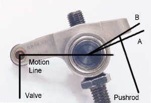
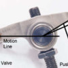
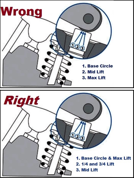
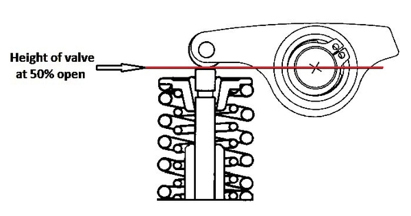
I've always been under the assumption that the imaginary red line joined two points: the center of the rocker arm trunnion, and the center of the roller tip trunnion. Hopefully these images convey my meaning:
I've always used Jim Miller's methods to set up various engines:
http://www.sbintl.com/tech_lib...ker_arm_geometry.pdf
Attachments
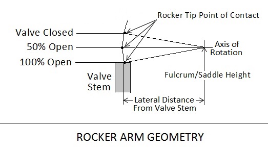
Its my picture.
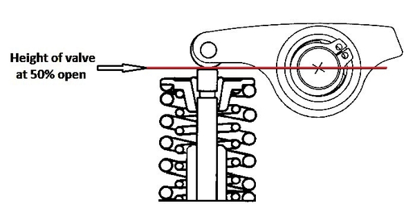
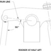
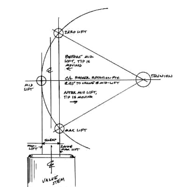
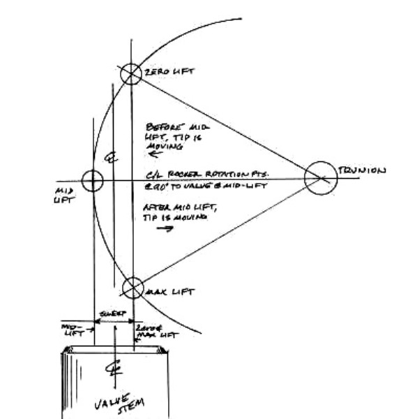
The goal of any valve train, as far as I'm concerned, is to perfectly follow the motion imparted by the cam lobes. The rocker arm geometry as I have drawn it makes no attempt to optimize geometry at the push rod cup; but it optimizes geometry at the valve tip. By optimum geometry I mean: (1) motion at the rocker arm tip shall be most linear, (2) side thrust between the valve stem and valve guide is minimized, (3) valve guide wear is therefore minimized too, (4) the width of the rocker arm tip's wear pattern across the tip of the valve is also minimized, and (5) valve motion imparted by rocker tip motion is maximized. The geometry as I have drawn it may not achieve the most overall valve motion (valve travel), that will depend completely on how well the rocker arm is designed (the angle of the push rod cup in relation to the rocker arm body). However, I feel in a street application the priority should be (1) high mileage durability and (2) maximizing performance … perhaps just the opposite of what the builder of a race engine may prioritize.
There are several "theories" regarding rocker arm geometry. Frankly the rocker arm instructions provided by some of the cam companies is the worst! Jim Miller's is OK. I've seen the "fulcrum line or motion line" explained as per the pictures you posted many times over the years, but with due respect to the author it is geometrically wrong. What I've drawn is correct.
There are two aspects this rocker arm geometry doesn't accomplish: (1) geometry between the rocker arm and push rod is not optimized, it relies on the design of the rocker arm to be reasonably "accurate". (2) Nothing has been done to center the rocker arm's contact patch on the valve tip.
The "ball end" design of push rods makes geometry between the rocker arm's push rod cup and the push rod less critical. Less than perfect geometry at that end will not result in the accelerated wear that poor geometry at the other end does.
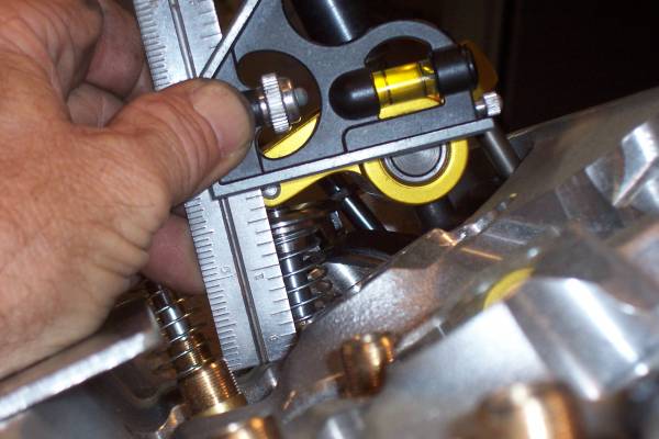
To set the geometry requires adjusting the height of each rocker arm and adjusting the lateral distance between each rocker arm and the associated valve. Adjusting all 16 rocker arms individually is time consuming; but its not too difficult with the head sitting on a work bench. This type of rocker arm makes that possible.
George P posted:"The goal of any valve train, as far as I'm concerned, is to perfectly follow the motion imparted by the cam lobes."
Agreed.
"The rocker arm geometry as I have drawn it makes no attempt to optimize geometry at the push rod cup; but it optimizes geometry at the valve tip."
Yes, let's ignore the pushrod side of the rocker arm for now, and focus on the valve side for the moment...
"By optimum geometry I mean: (1) motion at the rocker arm tip shall be most linear, (2) side thrust between the valve stem and valve guide is minimized, (3) valve guide wear is therefore minimized too, (4) the width of the rocker arm tip's wear pattern across the tip of the valve is also minimized, and (5) valve motion imparted by rocker tip motion is maximized."
So, to simplify just a bit....can we agree that the minimal sweep pattern (and therefore the most 'efficient' linear motion, etc.) at the valve stem tip is an end result of optimum geometry?
"There are several "theories" regarding rocker arm geometry. Frankly the rocker arm instructions provided by some of the cam companies is the worst! Jim Miller's is OK. I've seen the "fulcrum line or motion line" explained as per the pictures you posted many times over the years, but with due respect to the author it is geometrically wrong. What I've drawn is correct."
I will agree that most cam companies are barking up the wrong tree when it comes to proper rocker arm geometry, However, I believe that Jim Miller has got it right. I have been meaning to analyze this relationship in SolidWorks for a while now, this may be the kick in the pants I've needed to get it done...
"There are two aspects this rocker arm geometry doesn't accomplish: (1) geometry between the rocker arm and push rod is not optimized, it relies on the design of the rocker arm to be reasonably "accurate". (2) Nothing has been done to center the rocker arm's contact patch on the valve tip."
Duly noted.
"The "ball end" design of push rods makes geometry between the rocker arm's push rod cup and the push rod less critical. Less than perfect geometry at that end will not result in the accelerated wear that poor geometry at the other end does."
Agreed.
ABSOLUTELY!
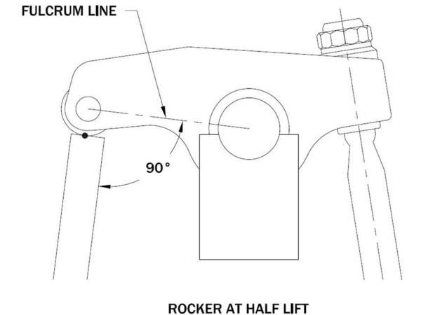
This image seems to depict rocker arm geometry using the centerlines of both the rocker trunion and the roller trunion:
While this earlier image depicts geometry using the rocker trunion and the roller tangent point with the valve stem:
I believe the first image will produce the better outcome...I'll 3D model both scenarios.
Let me get to work on that analysis...
Attachments
I ripped that first picture from the internet. I meant for it to make a basic point regarding "how" the rocker arm TIP sweeps across the end of the valve when the geometry is correct. But of course you're hung up on the point of contact being the axis of the roller tip …. which was not my point.
I should have dug-up this picture instead. This is another picture I created, this one is over a decade old, best I can remember. It was originally done to 1:1 scale.
Attachments
Hi George,
I drew up a quick 3D model of a rocker arm and a valve in SolidWorks:
In this model, the rocker arm is constrained to rotate about the centerline of the trunnion. The valve is constrained to move in a linear fashion along its axis. The valve stem tip and rocker arm tip roller are coupled together with a tangential 'mate'. This mimics the components as they would be installed in practice.
I set about to compare the differences between two distinct valvetrain geometries, I'll call them Method 'A' and Method 'B'.
Method 'A' establishes midlift geometry using the point of contact between the rocker arm tip roller and the valve stem tip.
Method 'B' establishes midlift geometry using the centerline of the rocker arm tip roller. This is the preferred method of Jim Miller.
Method 'B' produces a smaller, symmetrical sweep pattern at the valve stem tip. With any luck, the PDF file I've attached can be downloaded for a more legible drawing.
I hope this quick analysis can help anyone that's bothered to read this far... ;-)
Attachments
just curious,
does solid works do the trig for the contact sweep for you?
and could you provide the roller diameter?
this reminded me, I used to work hydraulic levers and links;
rule 1 was "Perpendicular at mid stroke"
(and in a sense, the same rule applied to the analog computers too)
"does solid works do the trig for the contact sweep for you?"
No, that needs to be done manually.
"and could you provide the roller diameter?"
I used a 0.500" diameter roller in the 3D model.
perryh posted:Can someone give me a quick primer on what these are?
http://store.yellaterra.com.au...s-ratio-1-73-yt6015/
Do these bolt onto factory head pedestals? Is that with or without machining the ridge off of the pedestal?
And are these the same thing, but for applications that use a larger 7/16" bolt instead (or factory heads that have been tapped for a 7/16" thread)?
http://store.yellaterra.com.au...s-ratio-1-73-yt6321/
And the advantage of these over a stud mounted rocker is that is that they are simpler than a stud mounted rocker? Simpler how? Like the factory, but stronger with the ability to adjust and a lack of guide plates?
***************************/vi...ic.php?f=6&t=342
Thanks!
The yt6321 are designed for the flat rocker pedestal with the 7/16" bolt holes. They come with pedestals with a pin hole which is then drilled through into the head with the tool that comes with them. When the pins are installed and rocker bolted to it, the rocker cannot rotate like a regular stud mounted rocker. No pushrod guide plates are required. I am not sure where I purchased mine, maybe Amazon years ago.
Check out this thread . I am not sure why I cannot insert a link to another forum but maybe try copying and pasting this link in a browser...
the351cforum.com/viewtopic.php?f=6&t=342
Someone was also asking about rockers for heads with the 5/16" bolt holes and ridges, it mentions RM Competition which could work out for you though it does not mention the bolt size on their webpage. Not sure if the yt6015 locks the rocker down from rotating like the yt6321, not sure if the RM Competition one does either. http://www.rmcompetition.com/rocker-arms-.html
CNC Motorsports seem to have Yella Terra listed, I bought stuff from them before. Other vendors may carry these also.
With reference to the sweep pattern of the rocker roller discussion, is it not the most important to get the smallest, but central to the valve tip, sweep possible? If possibly the rocker arm is higher or lower on its fulcrum or the valve tip is taller or shorter with maybe incorrect angles on the valve stem or rocker mounts, change slightly how the rocker tip rides on the valve tip. As long as the "sweep" is central on the tip and with the smallest "sweep" possible, this could be achieved using Method A or B depending on how it measures in real life?


