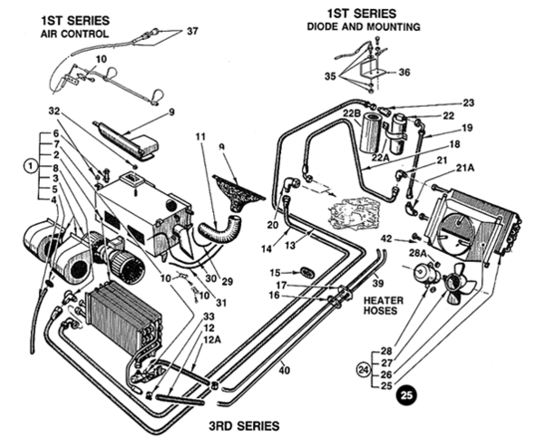
I 1st bought the rebuilt stock a/c heater box that was modified with an extra fan speed from the guy up in LA and that was a good purchase. I bought his pre maid A/C lines and that was a wast of good money. The lines were all clocked wrong an unusable. What I did was made up all of my lines with all the right fittings, marked and clocked them right and went back to my local A/C guy and had him swedge them. It took several trips down to my A/C guy to get it all plumbed. I charged the system with nitrogen and let it sit for 48 hours and re checked the pressure for leaks. This was the biggest pain in the ass I have ever experienced working on a car and if I would charge someone to do this job it would be so much they probably wouldn't have me do it. The only thing I like about the Pantera is the way it looks, My 70 T/A will lay waste to it on a road course, top speed or the 1/4 mile. After owning one I can see why they get crashed when driven aggressively. They do look cool though.
I do have to speak up because the Pantera is not what you say it is! Many people with money buy stuff, but do not know how to handle it… An experienced driver and with experienced, I mean somebody who has the technical knowledge and has the feel for the machine Will get exceptional performance out of the Pantera!
The Pantera is a raw machine… Mid engine with rear bias… You have to know what you’re doing! It’s the driver who keeps the car on the road!
I bought my 1974 911 Carrera When I was 22 years old, (which got me a job at BMW motorsport as test driver ) drove it for 18 years and let me just say I’m a rather spirited driver! Most of the 120.000 km I did in Germany on country roads and the Autobahn, Doing well over 150 miles an hour daily to go to work…
911 is well known as a Tail happy car (being rear engine which makes things even less forgiving) And you have to work for performance with a happy outcome ! The Pantera can blow the doors off the 911s of the period! I also got quite a few miles in Lotus Esprit turbo and Maserati Bora. You have to know what you’re doing! And I never, never ever damaged one of those cars! You have to learn how to drive and how to feel the car… It’s not something you sit in it and treated like a front engine, rear wheel drive car, which has a much larger envelope to catch a screw up! Overconfidence will get you in trouble… especially on a mid engine car ! You always have to respect the machine!
regarding working on the Pantera… There are not many things I haven’t touched yet and aside from the screwup some people did over the last 50 years encroaching on the original wiring, it is an easy car to work on.
and if you look on this forum, how many people have torn her whole car apart down to the last nut and bolt and rebuild it in the garage is a testament to the Pantera!
It’s not a Tractor like the Chevelle or a Mustang of the period - it’s a 70’s performance automobile but still built in a manner That normal, technically inclined person can work on!
here is just a few of the things I did:
https://pantera.infopop.cc/top...core-keeping-it-cozy
https://pantera.infopop.cc/top...uld-the-can-of-worms
https://pantera.infopop.cc/top...ng-why-which-and-how
https://pantera.infopop.cc/top...tock-disc-conversion
https://pantera.infopop.cc/top...ge-it-after-50-years
https://pantera.infopop.cc/top...rnal-fuel-filler-mod
and I did quite a few more….
I think your comments were absolutely unjustified and I’m amazed that nobody else was speaking up!


 The questions are :


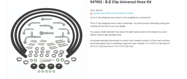 Larry -Is this the type of Kit that could be adapted ?


