
Replies sorted oldest to newest

The first diagram is the one that works very well in my TVR Griffith even though the overflow tank is located lower than the swirl.
The air bubbles present in the circuit accumulate at the top of the swirl and are expelled into the overflow tank when the liquid expands under the effect of heat during the first heating of the engine. It is the expansion of the liquid that creates the delta P between swirl and overflow tank. This air then accumulates in the upper part of the overflow tank and escapes if the pressure becomes higher than that of the cap. If there has been too much water poured into the circuit, the overflow also escapes. When it cools only liquid is pushed back into the swirl by the pressurized air at the top of the overflow tank since it is connected to its lower part, so there is never any air in the swirl .

In the second diagram connecting the overflow tank to the pump suction creates some radiator bypass, even if it is limited by the diameter of the pipes, and therefore slightly decreases the flow through the radiator. In addition, the swirl being connected at the top of the header, the air can be sucked into the swirl when the liquid cools and retracts.

But apparently both work well and it's up to each individual to choose.

Last edited by rene4406

the second diagram, ie continious venting.   besides the initial collection of air being expelled on heatup, it will also gradually deaerate the desolved gasses from the coolant.

to me, a significant enhancement is moving the pressure limiter (radiator cap) from pump discharge to pump suction.    given the flow resistance of the long tubes to the radiator, the original arrangement (and hand drawn) the pump suction could be at flash point

Last edited by jfb05177

Hello dear enthusiasts
Still thinking about optimizing my cooling system, I have many insights to understand:
1/ how to connect the overflow tank hose to the suction of the coolant pump on the water pump body ? We must use a specifical water pump ? Or we must updated the original water pump ? O we should connect it the radiator hose ?
What is the diameter of the "bottom connection..." ?
2/ I don't have a temperature sensor on my car currently, but a hose connected to nothing. Is this normal ?

See the pdf.

thank you for your support
willy

Attachments

DSC00033
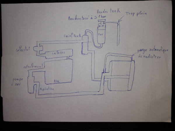
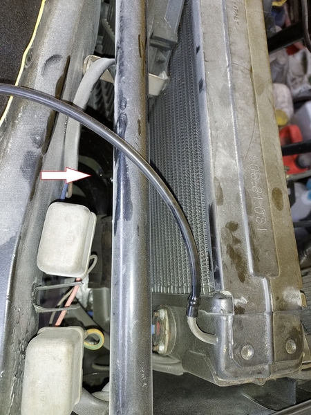
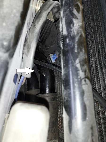
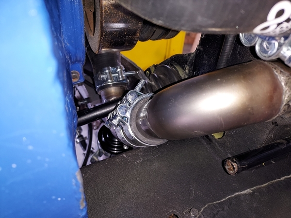
...I never did any of these modifications!! What I DID do was Disconnect and Cap the air bleed hose from the Radiator. I raised the Pressure Tank Much Higher 4" Taller to create a Air-Trap (See Pic). This traps all air in the system and is bled out to the over flow tank...the result is when you open the Cap after a cool-down, and water is re-filled from the over-flow tank...water spills out, because the pressure tank has been Automatically Filled to the Brim, Maximum. This is how the system is suppose to Work! NO Need for all this 'raise the rear of the car' etc.! Air was bled at the Radiator by loosening the capped banjo fitting, Twice. The second time after a Cruise. All air is out, pressure tank 100% Full.

Also, and this always causes controversy here...I changed the Direction of the Flow through the Radiator. As in Thermo Physics, heat rises...I connected the Flow to the Radiator to the TOP inlet and the Return to the Engine, of the Cooled Coolant, comes out from the bottom. Many here on the forum disagree with this??? But if You Look at all other Vehicles, GM's, Fords, Lambos, Ferraris...99 out of 100 cars connect the flow this way! The Pantera is the ONLY car that does it differently! Hot in the Bottom, and Colder out of the TOP, Already Heated by the Rising Heat. I posted this advice 10-12 Years ago and No One listened, but did all this Mumble Jumble, for air bleeding. In My View, Not Necessary!!

...Some of You on this Forum, know I took the Kat to the Mojave Desert in August of 2019:

The Ambient temperature 118F. Sustained cruise speed 80-90 MPH 5th Gear, and I'am talking for 3-4 Hours! 50/50 Prestone Anti-Boil 180F RS Thermostat and the 'MJ' Restrictor Plate installed. 4.9" WP Pulley, Pressure Tank CAP 16 PSI. 3 Sucker fans with Shrouds running at Full Blast. Engine oil cooler running with fan. Air intake box, NOT pulling engine bay heated Air. NO Pinging excepting, When I really Pushed it up a Hill. 91 Octane Fuel, 10.5 CR.

The 351 Cleveland Never got Over 195F. There's Your Proof. GODs' Own Truth! Take it FWIW.

MJ

Attachments

Images (1)
  • DSC00033
Last edited by marlinjack

Thank you for your answer, so by modifying 2 things on the 1974 Lady, raising the tank by 10cm and reversing the flow at the radiator would be better?  Knowing that I have a new high performance aluminum FLUIDYNE radiator do I have to reverse the flow too?  Regarding my question point 2 / probe missing normal or not?  Thank you in advance for your answer.  willy

Attachments

Images (1)
  • 16906203427898897375555201921178

OTIS, thank you Connais tu le diamètre interne de cette petite poulie, un plan dimensionnel de cette polie, car je pourrais la fabriquer ? Si je change par une petite polie donc je change de longueur de courroie ? Cela doit être une courroie spécifique ?     Concernant mon point 2/ tu n'a pas de réponse à me fournir concernant la non présence de sonde sur mon tank, est ce  normal  ?        Merci pour votre support.

Attachments

Images (1)
  • 16906510613377301929482590267780

OTIS, thank you Connais tu le diamètre interne de cette petite poulie, un plan dimensionnel de cette polie, car je pourrais la fabriquer ? Si je change par une petite polie donc je change de longueur de courroie ? Cela doit être une courroie spécifique ?     Concernant mon point 2/ tu n'a pas de réponse à me fournir concernant la non présence de sonde sur mon tank, est ce  normal  ?        Merci pour votre support.

La poulie permet de tourner 10% plus vite, elle a donc un diamètre primitif 10% plus petit que celle d'origine.

Les courroies existent dans à peu près toutes les longueurs, il suffit de regarder sur des sites tels que 123courroies.fr par exemple.


Pour la sonde de température il y a un trou taraudé sans le bloc en dessous du thermostat:

c'est un bien meilleur endroit que dans le swirltank pour installer la sonde  c'est plus précis et ça permet de suivre la phase de montée en température avant que le thermostat s'ouvre.


Pour les histoires de hauteur ne perdez pas de vue qu'on parle de pressions à chaud de l'ordre du bar alors que 10 cm d'eau correspondent à une pression statique de 10 millibar.

Attachments

Images (1)
  • mceclip2
Last edited by rene4406

Voici le piquage sur le tube de retour:


La poulie plus petite sert surtout lorsque le moteur tourne au ralenti ou à très basse vitesse, donc en ville lorsqu'il fait très chaud comme dans le sud de la Californie au Nevada ou en Arizona.

En revanche elle augmente le risque de cavitation à hauts régimes, surtout avec un moteur prévu pour prendre 7000trs. J'ai donc décidé de ne pas changer ma poulie dans un premier temps sous nos climats plus tempérés, je pourrai toujours le faire ultérieurement si ça s'avère nécessaire, cette poulie est facilement accessible par la trappe à l'avant du moteur. En prévision j'ai modifié le circuit de retour en utilisant des tubes de 40 mm et j'ai remplacé le grand coude en caoutchouc de raccordement de l'aspiration de la pompe susceptible de se "pincer" par des coudes eux aussi en 40 mm en inox afin de diminuer les pertes de charges et donc les risques de cavitation:

Les soudures sont affreuses, mais elles sont étanches et résistantes; soudeur c'est un métier et ce n'était pas le mien

Attachments

Images (3)
  • mceclip0
  • mceclip1
  • mceclip2

René

OK c'est clair pour moi, autre interrogation de ma part j'ai 2 tanks que je vais conserver. L'un est petit le "swrilstank" avec un bouchon avec un languette de verrouillage et l'autre tank "otherflow tank" avec un bouchon aussi mais simple.

Sur ton schéma que tu m'a fait parvenir, ton swrilstank n'a plus de bouchon ? Dois-je le modifier ?

Autre chose connecté le Flux vers le Radiateur à l'entrée du HAUT et le Retour vers le Moteur, du Liquide de Refroidissement Refroidi, sort par le bas qu'en penses tu ?

Willy

Attachments

Images (2)
  • 16907180831642141269644143623085
  • 16907181768486548149094932552229

Je préfère mettre un bouchon simple et étanche sur le petit swirltank mais qui laisse l'orifice du raccord supérieur libre, c'est à dire qui porte sur le haut du goulot et un bouchon pressurisé sur le grand vase d'expansion.

Raccordement de l'eau chaude en haut ou en bas, franchement je n'ai pas d'avis, dans un cas l'eau chaude monte par thermosiphon et dans l'autre elle redescend au fur et à mesure qu'elle refroidit. Il faudrait faire des essais. Dans les systèmes sans pompe, tel que les petits moteur deux temps des 50 ou 125 cc l'eau chaude est raccordée en bas du radiateur, mais le circuit est très court.

Hi Willy -

My “le tube de retour” is like Rene’s.

Mine has a short soft line (with clamps) at the radiator and the main part of the tube is a hardline.

It was much easier to route with the engine out.  It goes under the car to the rear bulkhead, and then over to the modified overflow tank.

There may be a few other sections that use soft rubber lines, but not many.

Good luck with your build!

Rocky

Add Reply

Post
×
×
×
×
Link copied to your clipboard.
×