

Step 1: have a friend absolutely mat the clutch pedal from inside the car. Moving the floor mat from under the pedal may be necessary to get ANY clearance from Step 2.
Step 2: insert a flat-shim feeler gauge between the flywheel and clutch disc through the ventilation/inspection hole in the bellhousing.
Step 3- read the max thickness of gauge that can be easily inserted without force.
Note that doing this check will un-compress any marcel. I will be surprised if anyone finds as much as 0.040" of clearance by doing this. That also means that each side of the free-floating clutch disc only gets 1/2 of whatever clearance you find. So- best results of 0.040" actually gives only 0.020" between the flywheel & clutch disc, and another 0.020" between the disc and clutch surface. That much clearance is marginally OK but any less causes drag on one or the other spinning surfaces, which wears the ZF synchronizers and eventually causes grinding when going into gears. Less clearance means more clutch-drag and wear.
Note also that doing the above clearance check means nothing if you do NOT fully mat the clutch pedal with each shift, in your everyday driving. Most people including me do not, and synchro drag is the results of getting in a hurry with your shifts. Synchro replacement costs will eventually cause severe wallet-pain to most owners.
Keep the faith. I got .050" clearance, so it can be done.
Also the flywheel that you use figures in to this also. You can pick up probably .010" by resurfacing it. Even a new one.
The Marcel was reduced for this reason, i.e., minimum required clearances. They picked up maybe, .030" by doing so.
Everyone with a Pantera NEEDS a Pantera SPECIFIC clutch assembly. Modify a Mustang unit at your own risk?
It is specific to a Pantera. It is minimally a generic unit. How much were new syncros? $600 or was that $900 each?
Depends on who actually does the work. If you order the parts after pulling your ZF and do a tear-down to determine what wore out- the synchro assembly, the gear cone which requires full replacement of that gear and maybe the mating gear as well, or all of the above, and your assessment is correct & you reassemble it yourself correctly, is one price.
Or crate the 155-lb gearbox as befits a $6000 assembly and ship it to an overhaul facility, synchro R&R done this way can run several thousands of dollars and several months down-time.
Also realize that all new ZF parts including gaskets only come from RBT Transmissions and everyone pays full retail for them. Overhauls therefore all have the same parts costs so any variation comes from cheaper labor rates or cannibalized used parts recycled into your gearbox. Nothing wrong with that except used parts obviously won't last as long as new ones.... Some gasket dimensions are critical, too.
Last bill I saw (a dozen years ago) including shipping to RBT, tear-down, inspection and reassembly with a few new gaskets and only an inexpensive thrust washer replaced- no synchro required due to a mis-diagnosed noise- then return shipping, was for $1100. Took a month.
quote:Originally posted by Bosswrench:
Depends on who actually does the work. If you order the parts after pulling your ZF and do a tear-down to determine what wore out- the synchro assembly, the gear cone which requires full replacement of that gear and maybe the mating gear as well, or all of the above, and your assessment is correct & you reassemble it yourself correctly, is one price.
Or crate the 155-lb gearbox as befits a $6000 assembly and ship it to an overhaul facility, synchro R&R done this way can run several thousands of dollars and several months down-time.
Also realize that all new ZF parts including gaskets only come from RBT Transmissions and everyone pays full retail for them. Overhauls therefore all have the same parts costs so any variation comes from cheaper labor rates or cannibalized used parts recycled into your gearbox. Nothing wrong with that except used parts obviously won't last as long as new ones.... Some gasket dimensions are critical, too.
Last bill I saw (a dozen years ago) including shipping to RBT, tear-down, inspection and reassembly with a few new gaskets and only an inexpensive thrust washer replaced- no synchro required due to a mis-diagnosed noise- then return shipping, was for $1100. Took a month.
What I was alluding too is simply it is better to put the correct clutch in the car now rather then have to rebuild the ZF soon after putting in the wrong one.
It seems to me to be a simple equation.
This just seems to me to be one of those areas in the car where some go to "Bonzo the Chevy clutch guy because 'obviously' the original engineering was wrong because the Italians wouldn't stop with drinking Bolla and spilling it all over the blue prints?"
That simply isn't true. It is well engineered for 1970 limitations. It needed more development to improve it.
Conspiracy theories have their place, but not here with this car.
This pic of a Turbo shows how the mats should be cut to keep them away from the pedals. There is no possibility of the pedals bottoming out on the floor mat here.
If you did the pedal box modification of moving the mounting plate forward, then the pedals wind up closer to the floor at full travel than stock.
Check your mats.
Attachments
Images (1)

Well
I have received my new clutch spinner plate from The USA (McLeod)
so now have
both New McLeod pressure and spinner plates
new master and slave, quality stuff too from Roland Jaekel
New crank bearing
New release bearing
and not a gear can now be selected with the engine running.
over 3 months of buggering about with a sodding clutch system, unbelievable
adjustment of slave rod to longest possible to 0.5mm free play makes no difference.
bled with vacuum system no play in pedal.
if I stop the engine and select first gear as soon as I begin to release the pedal we are off and running.
I never thought a clutch system could be so problematical
How much stroke does your slave have as you depress the clutch?
If << 16mm, the problem is with the master cylinder and slave.
IF ~~16mm, the problem is with clutch
If << 16mm, the problem is with the master cylinder and slave.
IF ~~16mm, the problem is with clutch
Re the over-center clutch assist linkage: when the L model came out with it, Ford's description of it's advantage was, 'The effort is initially higher than before but quickly drops off to a lower effort than normal. This allows a driver to comfortably hold the clutch pedal in at stoplights....'
Peter, last summer just on the way to join my fellow Pantera drivers in France I had Clutch issues. The Bolt that links the pedal to the master snapped and I had to repair it really fast, na never mind long story. My point is that I had really a lot of trouble bleeding the air out after the reapair and could not figure out why. Until it struck me the cars was pointing nose down in my driveway (maybe 10° slope) and after I put a Jack under the front and lifted it the air got out. I use a vacuum device to bleed btw.
A small air pocket was trapped in the master cylinder causing the trouble.
A small air pocket was trapped in the master cylinder causing the trouble.
I think I have been making some of the problems with my clutch myself without the help of others.
Not knowing a great deal about the Marque, I tackled the clutch just as I would have with a TR2, E type or any other classic car that over the years I have been fortunate to own.
A clutch is simple, or so I thought and an effort reduction kit I also knew nothing about.
in short I have never put the adjustments recommended with the Effort reduction kit, and just tried to set the clutch up like any other bloke would.
I have spent a while today reading up on the ins and outs, found that I have measured the Master cyl rod in the wrong way to start with.
At least I have the quadrant around the right way, so I shall now set it up as per the settings in the books.
Master 2.91"
slave 3.07"
and hope for a decent space between flywheel and disc.
I must thank all those far more knowledgeable than myself for their efforts to help this numbskull, but hopefully we are on the way to getting it working properly.
Best wishes and a happy xmas to you all.
and the days are getting longer again too Pete
I GUESS your quadrant looks like this now.
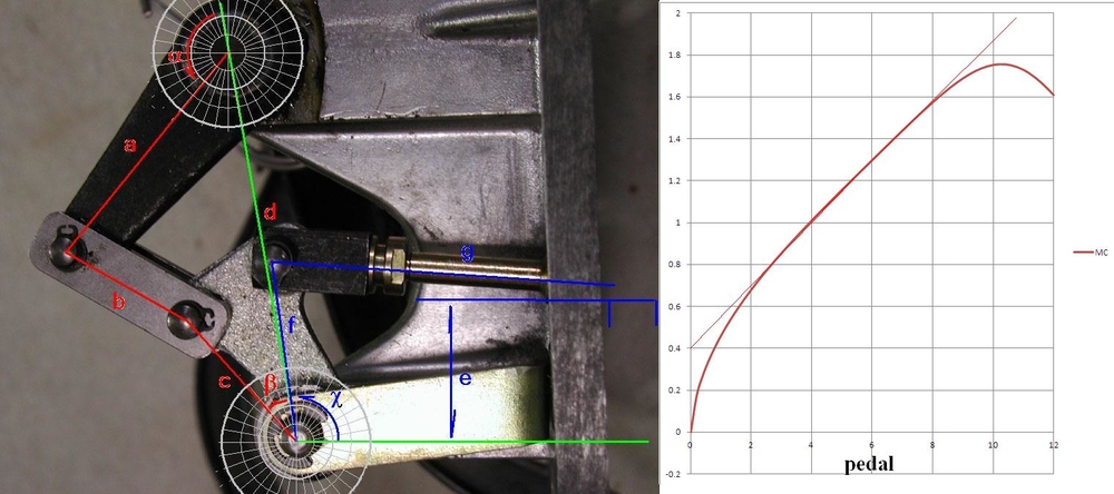
the angle between links b & c would be the critical in the setting of the master cylinder rod. if b & C are near in a line, the pedal will lock up, you want the shallow angle about as shown. More angle and you start loosing MC stroke (and thus slave stroke)
the angle between links b & c would be the critical in the setting of the master cylinder rod. if b & C are near in a line, the pedal will lock up, you want the shallow angle about as shown. More angle and you start loosing MC stroke (and thus slave stroke)
quote:Originally posted by JFB #05177:
I GUESS your quadrant looks like this now.
the angle between links b & c would be the critical in the setting of the master cylinder rod. if b & C are near in a line, the pedal will lock up, you want the shallow angle about as shown. More angle and you start loosing MC stroke (and thus slave stroke)
No it doesn't, it was like this before you told me to turn it around, this is just so confusing see page 1 for your pic showing the incorrect fitment, and your comments.
Please accept my sincerest apology in adding to the confusion.
My experience so far has only been “keyboard and monitor” and I assumed the photo I found and used to determine the motion of this linkage was correct. I was not aware of the Mike Drew article (posted earlier by David Nunn).
After studying the MDrew article, I went to the barn and looked at my linkage that has been rusting for 30+ years. As to which way is correct, I don’t KNOW. My modeling equations of the “possibly wrong” orientation did provide realistic results. Unfortunately the progression of dementia is such I doubt I will be able to model the “possible right” orientation and make a comparison so I would actually know for sure.
Again I apologize
Attachments
Images (1)

There is no need for apologies at all, I am very grateful for help. There isn't a definitive write up for Idiots like me.
Thank you for your latest picture, the slightly rusted one, My bracket is now that way around.
so with this latest info I will begin to put it all back together, fingers crossed, I have to be on the homeward run now!!! best Pete.
PS just noticed the split pins, what a grand idea.
Thank you for your latest picture, the slightly rusted one, My bracket is now that way around.
so with this latest info I will begin to put it all back together, fingers crossed, I have to be on the homeward run now!!! best Pete.
PS just noticed the split pins, what a grand idea.
quote:Originally posted by Peter Fenlon:
There is no need for apologies at all, I am very grateful for help. There isn't a definitive write up for Idiots like me.
Thank you for your latest picture, the slightly rusted one, My bracket is now that way around.
so with this latest info I will begin to put it all back together, fingers crossed, I have to be on the homeward run now!!! best Pete.
PS just noticed the split pins, what a grand idea.
In reply to my own post.
NO luck, with the arm now in the right position
I cannot get more than 12/13mm movement of the slave cyl piston.
I am to try and go back to a direct no effort reduction system and see what transpires.
I have no leaks.
pedal pressure is continual with the new slave and master cyl.
I have an armoured flex line so no bulging.
I see there are different spinner and pressure plates depending on the ZF gearbox fitted,
sadly I didn't know and just asked the vendor for a clutch spinner and disc and the McLeod stuff came through.
I also noted that one poster said the height of the clutch pedal should be 1/2" higher than the brake pedal, I found this impossible to adjust when the effort reduction kit is fitted.
I know this will be more difficult to measure, but your pedal travel should be stroking the master cylinder ~29mm to get the ~16mm at the slave.
your 13mm at the slave implies only ~23mm at the MC.
Is your MC the original ~19mm BORE? with the slave bore of ~25mm? vendors do sell a long stroke slave which has a smaller bore. (smaller bore gives MORE stroke from the same MC)
If the 12mm slave stroke is all you can get, then you might consider changing the length of the lever arm to the ToB?
Peter, please tell me which procedure you use to bleed the air out of the system?
Even a tiny air bubble trapped in the system will hinder travel of the slave.
Even a tiny air bubble trapped in the system will hinder travel of the slave.
quote:Originally posted by goodroc:
Peter, please tell me which procedure you use to bleed the air out of the system?
Even a tiny air bubble trapped in the system will hinder travel of the slave.
I have tried using a vacuum system, using my compressor.
Also the good lady in the car pumping, and myself at the slave cyl nipple/zerk.with tube in half filled bottle.
2 questions for those who have working clutches.
1 how long is the travel on your slave please when pressing the pedal fully down, in mm if possible
2 is there a factory figure for the travel?
Peter I understand your frustration. Partly caused by your own "I just assumed" approach 
There could be more than one reason for your troubles. Please tell me if/how you continued after fellow Pantera owners gave you their feedback? i.e.
1. Did you measure with a feeler gauge how much play between the clutch plate and flywheel when the clutch pedal is fully down?
2. Did you extend the fork bolt on the master to full? (its where the angle between b and c is a few degrees less than 180°) That will raise the pedal towards you (when not pressed) so it sits higher than the brake pedal and give maximum/full stroke on the master.
3. Did you remove the shift gate when troubleshooting to avoid misalignment being a factor.
4. Absolutely all air must be bled out.
5. Seems like you have managed to put the right parts together but also check the direction of the clutch plate. Only one side can be facing the flywheel! (should be marked)
I am sorry if this all sound so basic but I am just trying to brain storm...... I never had any of those problems. I bought a new McLeod Kit and removed the bell housing from the ZF to be able to carefully check/measure and adjust for required play between pressure plate (multi fingers) and throw out bearing. I rebuild the master and bought a new slave. All done on the same occasion.
1, there is no room for a feeler gauge between the plate and flywheel.
2 the geometry of the effort reduction system prevents this, I have yet to go none effort reduction by fitting the correct rod, which I assume (!!) will allow the pedal to be above the brake pedal.
3 alignment is not a problem, gate removal isn't needed
4 again all air is out, pedal is solid
5 plate is in correctly.
What is the travel of your slave piston?
I do appreciate assistance, I think all other posters are absolutely fed up with this problem that they have either solved or not met.
thank you for your continued help.
best Peter.
Peter you should not have to remove the effort reduction kit? What I mean by extending the rod is to install everything but NOT tighten the counter nut on the rod. Then with your fingers or a needle plier turn the rod to its maximum extension just prior to b and c being in a straight line (linkage becomes over-centered).
That should bring your pedal up and increase the possible travel/distance on the master.
I cant check my slave travel tonight but i will try to do it tomorrow and let you know.
That should bring your pedal up and increase the possible travel/distance on the master.
I cant check my slave travel tonight but i will try to do it tomorrow and let you know.
Add Reply
Sign In To Reply