
Tackling the self bleeding-swirl tank set up.  This is what I have come up with after scouring posts and articles.

I am going to use the original system tank as is as a swirl tank. Install NAPA  BK 7031419 4lb pressure cap or cap with no lower gasket (only sealing at the top lip)

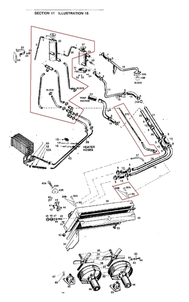
Run a 1/4 hard line with hoses from the port in the upper level of the overflow to a nipple in the left upper corner of the radiator.

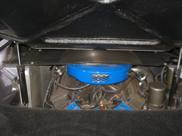
My concerns are; I didn't read anything stating exactly how much higher the overflow should be mounted. Will my mock up height be adequate?

Any suggestions for a replacement spacer for the void between the flat body and curved overflow tank? Upon disassembly what ever it was, crumbled to pieces so I don't have a sample.

If you see any Red flag areas please let me know. PXL_20231109_024213352~2PXL_20231109_025137951~2PXL_20231109_025144441~2

JerrySr

Attachments

Images (3)
  • PXL_20231109_024213352~2
  • PXL_20231109_025137951~2
  • PXL_20231109_025144441~2
Original Post

Replies sorted oldest to newest

In my opinion and if I understood correctly, this is a very bad idea, the line which starts from the top of the swirltank must arrive at the bottom of the expansion tank in order to suck up liquid when the engine cools down and the liquid shrinks. If this line comes to the top of the expansion tank like you plan to do, it will suck in air!!!!!

But perhaps I misunderstood your project.

No, I think he has it correct.

The large (expansion) tank is under suction from the water pump fitting, via the connection at the bottom of the expansion tank.  The air in the swirl tank moves out into the expansion tank - the swirl tank becomes a “de-gas” tank as it was originally designed.

My tanks are at about the same orientation (relative elevations) as you show…. When the system reaches equilibrium, the water lever in all the tanks will be the same (at the level of top of the swirl tank).

Rocky

Interesting idea to use the top overflow on the swirl tank, and mods to the gasket.

Last edited by rocky

I wrote out a detailed (detailed in my mind)  plan on function and layout so I could wrap my head around the concept. What I think is overlooked is that the flow in the tanks and the radiator are reversed in the self bleed/swirl tank mod.

As I understand it, in the original config Rene would be correct but reversing the flow changes everything. Again this IS my first RODEO (Pantera) and these are my Monkeys (mock-up)  lol. Any input is welcomed 😁

Rocky I hoped the tank elevation would be good, filling the system is tough enough I'll bet. " I've only done it a couple times and that was this car, 42 years ago ! "  Keeping the system tank cap will help maintain a stock look and give me better access to mostly fill the system.

Any concerns of leakage with the gasket only cap should be addressable. I know I have seen simple swirl tank caps with no relief spring and lower seal over the years I simply can't recall what vehicles

Just my two cents on this issue, but most of the worlds panteras have functioned just fine for the last 50 years without these radical cooling system modifications.

my car incorporates a top of the radiator airbleed piped into the pressure tank, and I have found that to be an effective approach to eliminating air pockets  

Air in the system is only a problem after the system has been opened, which for many owners seldom, if ever, happens.

One will spend far more time, not to mention money, creating the modified system then they would spend properly bleeding the cooling system when the need arises.

Larry

The only modifications I made to my Pantera are:

- a "simple" cap on the swirl tank, that is to say it leaves the upper outlet free with the small pipe which goes to the bottom of the expansion tank

- the temperature probe directly on the block.

- A Flowkooler water pump

- A 16'' fan added behind the radiator


The expansion tank cap is rated at 18 PSI I think. There was originally a small +/- 1/4" pipe that connects the top of the radiator to the large return tube to the pump, I obviously kept it.

The thermostat is a Robertshaw purchased from Summit.

The small outlet on the top of the block and the small inlet on the pump are connected to the radiator of the cabin heating system


So far I have only tried stopping with the engine idling or fast idling and it works great. I can clearly see the temperature rising then when it reaches 180°F it drops suddenly before rising gradually, at this moment the motor outlet tube becomes hot and a few seconds later the large outlet tube of the swirl tank also heats up, the radiator then begins to heat gradually until the fans come on. I know the system degasses automatically because I have to add a little fluid to the expansion tank when the engine has cooled down after the first warm-up.

Last edited by rene4406

I 100% concur that many/most Panteras need a little to no modifications. 👍

My vehicle had 2 modifications, vent on top of the radiator (diy) and split pass copper brass radiator (per TSB)  I do not know for sure if it suffered overheating issues but from what I see it most certainly suffered from wide fluctuations of the temp gauge from the location of the sensor and trapped air. With no additional temp gauge and no hand held infrared temp sensors  readily available 30 years ago who really knew?

If the car was in good operating condition and a driver I would probably do no other mods than what was done but that's not my case. My tanks were rotted out, hoses toast, coolant tubes toast and crusty OE style WP
So my case is- what the heck I'm already in there. The patient already sedated may as well do it now.

Other than these "helpful" mods to build in a level of margin -("I think that was a loose quote from Boss")  a dual pass radiator,  better fans,  take the load of the fans off of the ignition by adding relays, possibly moving the temperature sender to get better accuracy, putting in a bleed so you can properly/easily fill the system and keep air out of it, Make sure the thermostat's correct with the restrictor, make sure the hoses don't kink and have internal support or solid enough hoses as to not collapse, possibly a water pump with better impeller, under drive pulley- not sure if I missed anything lol)are all helpful 😁👍

David, thanks for the advice. I will drop or raise the tanks to change the level of those two tubes.

I WANTED a similair arrangement as You with two caps.   Unfortunately the neck of my swirl cracked (just as they were loading it to bring back)

the quick fix was to put a dome end on top of the swirl.    I now can greatly see the advantage to have the swirl as a place to fill.

My right side engine cover had a hole cut and the expansion tank raised to where the cap is flush.    My plan was to open expaision and fill at swirl to full,  leaving the space in expansion tank for expansion.

I've had several events in the past week on my returned pantera,  I am now "searching " for the expansion tank level where I just "pee" at full expansion.

Using a wooden "dip stick" i think i now have expansion level cold at top of my domed swirl.    Possible plan is to put a nice screw in plug,  (or just leave as is)

Here is the drawing for the instructions I provided shop

I have attached the entire instruction and MY reasoning for the modifications.   the shop was instructed that verbatom was not need, just the intent.   they did an excellent job and I will get some photos of thrier work soon

Attachments

Images (1)
  • blobid0
Files (1)
Last edited by jfb05177

Before I forget to ask is part  #26  on the the long tank just a thick rubber block?

Looks like my set up will work with some adjustments, thank you for the great information. I think I know where some after install tweeking may be needed.  

Your diagram is a little confusing because I don't have 2 large outlets on both tanks, just the shorter one.  ( No brain power left to mentally decipher how all of the extra hoses and crossovers work in that diagram lol). The long tank has 2 that are approx 5/8  but the principle seems the same. I really don't want to have to cut a hole in my engine screen for clearance so I will be ultra conscious of the heights and test fit the cover. (super helpful incite )

Thanks Jb

JerrySr

I'm the middle of this modification/engine install

what I would do differently: the shorter tank, I would have a threaded cap with oring and bung installed of the largest diameter I could find. Then on top of the cap come out with the 1/4" barb

as it sits you basically fill the system through the 5/8 heater hose that goes to the top of the water pump.

Attachments

Images (1)
  • IMG_3389

Nice setup, clean and uncluttered. Do you find that the crossover line (tank to tank) is enough pitch?  Looks almost level like mine.

The threaded cap is a great idea.  Agree on the 5/8 full, that's another reason why I wanted to maintain a cap in the smaller tank. To "mostly fill through then too off through the larger tank.

Thanks Bell

I don't think the line from tank to tank needs to have a pitch at all, as the fluid in the smaller tank expands it spills to the taller tank and gets sucked through the bottom.

if you left the radiator cap style on the smaller tank, you could just modify the cap  so it seals to the top and use the existing overflow line to the taller tank.

@jerrysr posted:
that's another reason why I wanted to maintain a cap in the smaller tank. To "mostly fill through then too off through the larger tank.

I DID too!   But, using a long thin flex tube funnel, AND two people I know the system (4 Gallons) can be filled going through the gap between open deck.   for the three days I have car back, I have used a 10" dowel to check the lever.  I can't recall exactly but my expansion (big tank) is 6" higher than top of swirl (small tank). 

Jerry, my drawing depikes the tanks after modifications are made, thus my large tank had multiple barbs put on side.   My naritive gave instructions for techs to fabricate

Bell, do you expect a cold volume of air in the big tank, or do you have a third reserve tank for the large tank to suck back coolant as cooling.

its been a while (and I doubt if I can do it now) but my 6" higher is to allow the expanding coolant to compress the captured air AND no spill from large tank (with radiator cap)   I might have an illustraion of the expected pressure rise verses diffent large tank elevations. if intersted (but I wont be able to explain)

It’s funny, but what I use to check the level is a piece of underwear seam with a bullet zip-tied into the end of it.

(I am certain there are alternative approaches)

But what you do is have about a 12 inch piece of flexible fabric with a weight on it. You mark a line on it so you know how far to lower it (you align this line with the TOP of the overflow tank) and then, when you reel it up, the wetness level is the fluid level inside your overflow tank.


PS… You don’t really need a catch tank, because once your system reaches equilibrium, it will stop peeing fluid out. At that point you have set it, and you can forget it….  

Except all of us conscientious Pantera owners make sure that we have a good fluid levels, so we will check it every outing!

Last edited by rocky

The large tank should have a pressure cap on it, it was suggested to me to run an 8psi cap.

so, how the system works in my mind the smaller tank works as usually, except instead of pressurizing and blowing off into the large tank, it simply spills into the large tank as it expands.

the bottom of the large tank has suction going to the water pump.

so the when the fluid goes through the thermostat, it goes to the top of the small tank, then from the bottom of the small tank it goes to the top of the radiator ; any extra air or fluid goes to the large tank either from the small tank or from the bleed line at the top of the radiator.

from the bottom of the radiator it goes to the water pump also to the water pump (suction side) is the hose from the bottom of the larger tank.

the only problem I could see is if you don't have enough fluid, any extra fluid would blow off out of the 8psi pressure cap on the large tank.


this is how I have it set up and my understanding of the set up, I could be wrong.

But why bother to complicate a system that works very well with a very little modification? Replace the pressurized cap of the small tank with a “simple” cap and the system works perfectly and degasses automatically.


A long time ago in France there was a humorous television series called "the Shadocks" it told the adventures of imaginary characters whose motto was "why make it simple when you can make it complicated?".

Without wanting to offend anyone, it seems to me that some of you would have made very good Shadocks.

Last edited by rene4406
@rocky posted:

It’s funny, but what I use to check the level is a piece of underwear seam with a bullet zip-tied into the end of it.

(I am certain there are alternative approaches)

But what you do is have about a 12 inch piece of flexible fabric with a weight on it. You mark a line on it so you know how far to lower it (you align this line with the TOP of the overflow tank) and then, when you reel it up, the wetness level is the fluid level inside your overflow tank.


PS… You don’t really need a catch tank, because once your system reaches equilibrium, it will stop peeing fluid out. At that point you have set it, and you can forget it….  

Except all of us conscientious Pantera owners make sure that we have a good fluid levels, so we will check it every outing!

Not sure about you Rocky but my underwear fall down after the elastic is all wet (especially if my front underwear pocket.is full of bullets ) 🫣🤣😂 or maybe I don't quite comprehend.

I'm hoping for a semi set it and forget it method,  check it before I leave home and not being required to carrying around extra coolant and a stick or strip of underwear 😊

In theory I wouldn't think a catch/overflow tank would be needed after the first "burping". At least I'm hoping not.

It’s a little frustrating, as I can’t turn up my super-duper tool for demonstration, But as you can see, my expansion tank is underneath my side cover. With a flexible “dipstick” as I have described, it’s easy to pop the cap off, and slip it into the tank, to get an accurate water level reading.

The same gauge could be made with a piece of cotton string, and fishing weight.


Anyway, it’s also quite interesting a number of people advising against this modification.  Lots of people do things to their cars because they’ve done some research and decide that’s the way they want to go.  Why not?

Have you heard a lot of people who have made this mod, and then are complaining that it doesn’t work? I certainly have not. I think it’s worthwhile, and it’s giving me extra cooling system margin.  I live in Arizona. It gets pretty hot around here.

Chuck

PS.  I will keep looking for my super-super tool, though, and I will post up a picture when I can!

DC3FB4CC-6DC4-4C06-9229-FBB04D93A7A4

Attachments

Images (1)
  • DC3FB4CC-6DC4-4C06-9229-FBB04D93A7A4
Last edited by rocky

Bell, The 8lb cap would limit the whole system to 8lb max pressure irregardless if small tank cap was 16lb.  If it is a closed system (as described) suction or discharge doesn't matter it will equalize pressure and find the weakest point to exit . The purpose of the pressure is to raise the boiling point of the coolant, coolant has a higher boiling point than water and for every 1lb pressure raises the boiling point by 3degrees.(antifreeze raises it a little)  Internal hot spots (flow dead ends) in the block/heads may boil without proper pressure, that's why most cars run 16lb for a margin of safety)  modern cars fans don't kick in until well over the boiling point.

Panteras use relatively low temp sensors in the radiator to regulate fans which is not the hottest point of the system. The coolant around the cylinder walls/heads is usually much hotter, especially during hot soak.

(From your description I would think your system regularly discharges small amounts of fluids due to the 8lb cap pressure , block hot spots and heat soak. I would think it would eventually seek some consistent level but change pretty drastically according to heat load.

Just my opinion, your mileage may vary.

Let me wade in where angels fear to tread.

I cant put my hand on the source but my understanding was the pressure drop from the top of the radiator down the small diameter steel bleed line to the tank locations is about 2-3PSI. If the small tank is running a 15psi cap and the bleed line from the radiator is feed into the large tank you can have a 12-13 PSI cap on the large tank and the system will be pretty much in balance. I did this and included an inline valve in the radiator top bleed line such that once the system is pressurised , you can open the valve and you can hear any bleed into the large tank with no associated loss of fluid out of the large tank. There is almost no loss of fluid with this arrangement and the system sees the full small tank cap pressure.

Initially I did get caught by the depth of the necks on the vendor supplied replacement tanks. By recollection they were 26mm not 19mm like the old tanks  which was a bit of a trap for a trusting young bloke from the bush. Just something to watch out for as 0 PSI doesn't work.   

Having trouble with  the patented fluid level measurement device- may have to buy some undies to get the elastic .....!

The advantage that I see in this diagram is perhaps to facilitate the filling of the system....... when there is no cabin heating system which creates a path between the exit of the block, thermostat closed, and pump suction.
But at the risk of appearing pretentious towards a Caroll Shelby chief engineer, the simple old engineer that I am persists in saying that the simpler scheme with only two tanks works very well.

Hi, I will get some photos and a drawing with dimensions together and post them
on the forum.


On Saturday, 11 November 2023 at 19:21:25 GMT, The De Tomaso Forums <alerts@crowdstack.com> wrote:

[New Reply Mention] Input needed, Swirl system mock up
| == To reply by email, write above this line. == |
|
You Were Mentioned
|
|
You were mentioned in the following post:
|
| Input needed, Swirl system mock upJReply by jfb05177
@Mike Barnby posted:
Hi , I made this system ....


I LIKE that!    if it was on the market I would hhave bought one>

Love to see a pic installed

[ View Reply ]
|
| The De Tomaso Forums
You received this based on your notification settings. You can adjust your settings or unsubscribe anytime.
|

Ref. my coolant system drawing.

The top portion of the dual tank is 9" tall and the rad cap is extended out from the top because it would hit the deck lid. In the photos the smaller red pipes (1/4" bore) are the overflow from the rad cap housing and the bleed to the radiator. All the other dimensions are the same as the original tank and all the pipes go to the original positions. The bleed to the radiator, which is a Chevy Corvette allloy racing rad, is via a stainless steel tube running parallel to the main coolant tubes.The 5/8" bore tube from the bottom of the top part of the new tank joins to the top of the bottom hose just before the water pump. You can buy a kit from the silicon hose suppliers that allows you to punch a hole in the tube and bolt in an adaptor for the 5/8" bore tube. I have a cover on the top of the tank that I 3d printed to hide the welds.  Just fit and fill the system it self bleeds, only half fill the header tank because of expansion. I had mine made in aluminium alloy but you  could use the original steel tank sutibly altered.

Attachments

Images (4)
  • Header tank swirl pot 1
  • WP_20231112_16_26_04_Pro
  • WP_20231112_16_29_04_Pro
  • WP_20231112_16_29_47_Pro

Add Reply

Post
×
×
×
×
Link copied to your clipboard.
×