

Looks good. But wear a proper mask when painting. Being able to pick ones nose after a paint job and get coloured nose pickings is not a good thing...
The wheels look great!
Rick -
They came out super! Thanks for the those babies!
Can't wait to see your car on the road!
Chuck
They came out super! Thanks for the those babies!
Can't wait to see your car on the road!
Chuck
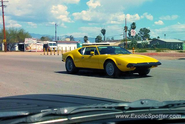
Just got these pictures -
What do you think?
I'm seconding Garth's sentiments on yellow cars, espoused here (See Page 2):
1971 Pantera Pre-L #1579 Yellow
What do you think?
I'm seconding Garth's sentiments on yellow cars, espoused here (See Page 2):
1971 Pantera Pre-L #1579 Yellow
Attachments
Images (1)
")
")
")
Nice!
I like the wheel
quote:I like the wheel
That's how I tell my car apart from all the other Yellow Panteras in the neighborhood!
Rocky
_(Medium)")
quote:Originally posted by Mark Charlton:
Thats a very nice website you have Mark, I think you are happy that's on your place still cold outside ,you can spend a lot of time on your webside.(LoL)
Simon
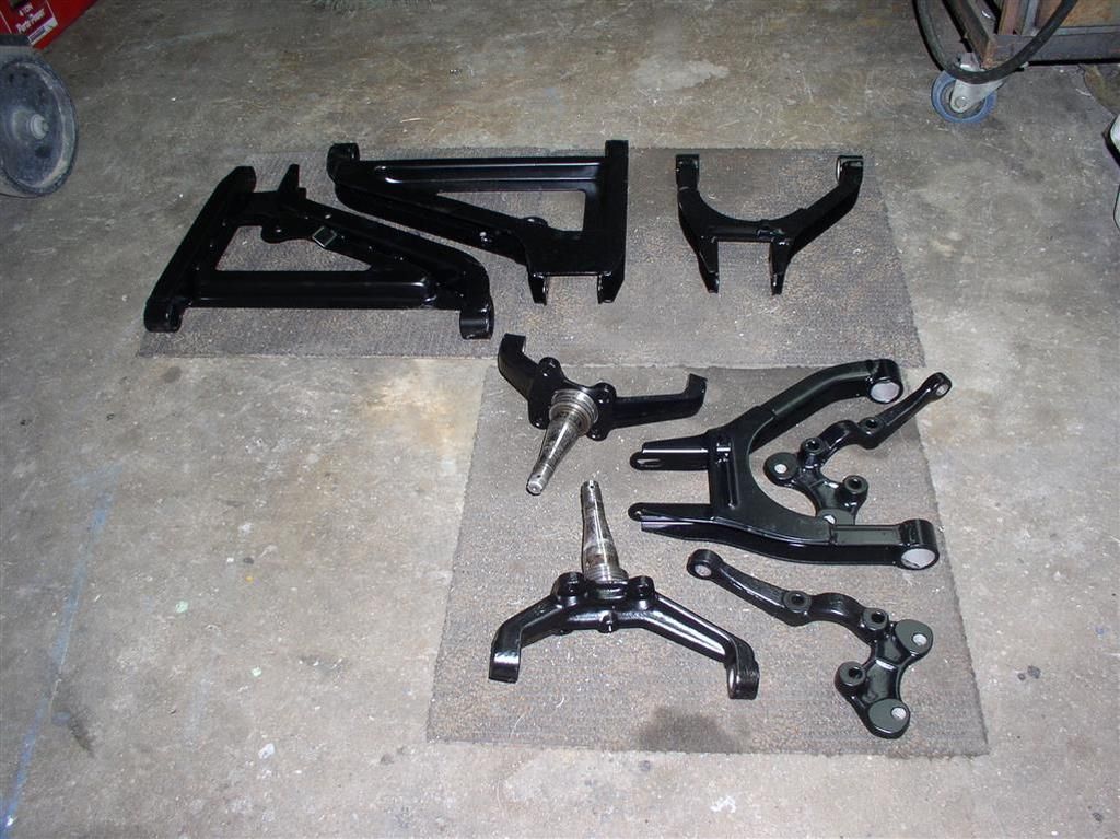
The Next Project - Front Suspension Upgrade
We are working on the next project - an upgrade of my front suspension components. The goal is to replace the old parts, and add a couple additional performance and reliability features along the way.
Main Items:
New Ball Joints and TREs
New Wheel Bearings and Seals
Adjustment of Brake Hose Routing
General Cleanup
Performance / Reliability Features:
Upper Ball Joints Milled for 2* More Caster
W-Wadeco Camber Lock System
Powder Cost Suspension Parts
Zerks on All Ball Joints & TREs
Painting of all Exposed Steel
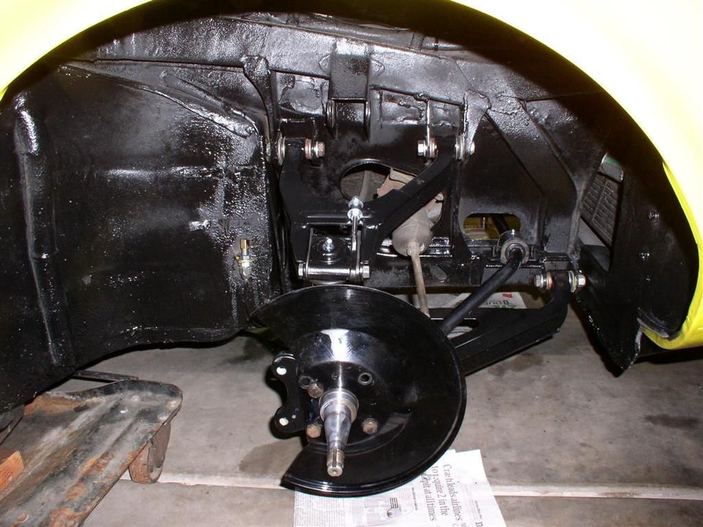
Here's a picture to get you interested.
Here is a slide show of the work to date. I will add more as the reassembly progresses.
Suspension Upgrade - Slide Show
Rocky
We are working on the next project - an upgrade of my front suspension components. The goal is to replace the old parts, and add a couple additional performance and reliability features along the way.
Main Items:
Performance / Reliability Features:
Here's a picture to get you interested.

Here is a slide show of the work to date. I will add more as the reassembly progresses.
Suspension Upgrade - Slide Show
Rocky
to push out the arm bushings, did you have to saw off the "big end"? A detail photo of your tools would be appreaciated
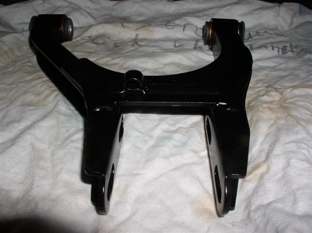
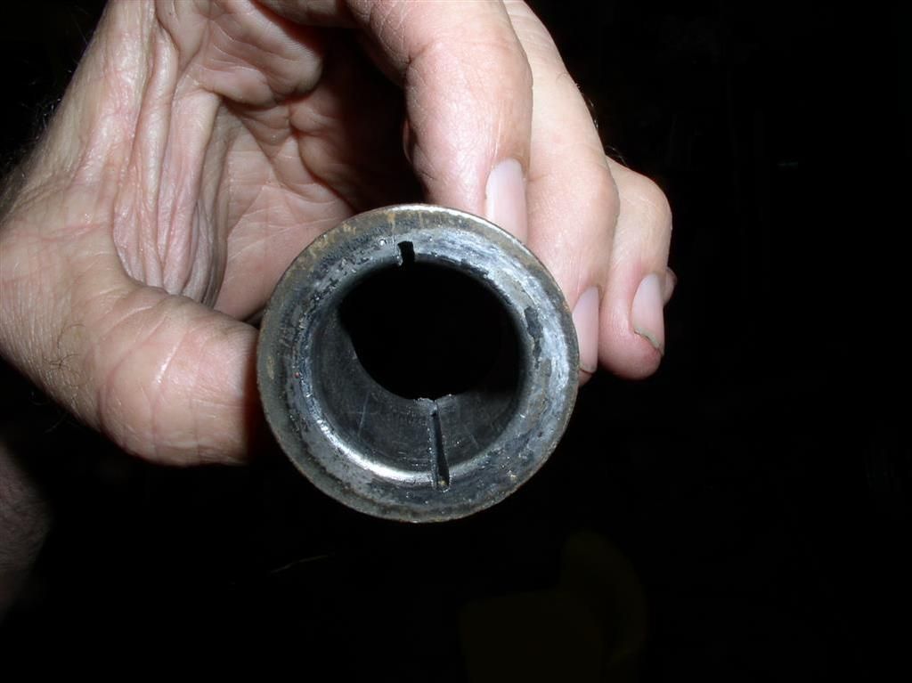
Well - to give you the honest truth, Wade (MarkIV/4280) handled that part*, but what he did was get a short height Sawz-All Blade, and cut the metal bushing housing top and bottom.
Careful cutting (not all the way through) relieved the pressure, and the bushings were then pressed out. The cut was longitudinal along the bushing housing.
I'll throw in a picture of one of the cut housings.
I believe that I left out a lot of the swearing, re-fixturing, pounding, and hammering that was still required. I saw the rubber pieces, and they did not look like they came out willingly.
Maybe Wade will post up a description of his technique.
Rocky
* as he handles 75-85% of my projects... Nevertheless - I am moving up in my skills qualification. I am now approved to sandblast on my own, and to do minor filing and scraping work. Oh, yes... Painting. I am authorized to do painting (rattle can only) without supervision.

PS> (Seriously....) Thanks, Wade for your help on my project!!
Careful cutting (not all the way through) relieved the pressure, and the bushings were then pressed out. The cut was longitudinal along the bushing housing.
I'll throw in a picture of one of the cut housings.
I believe that I left out a lot of the swearing, re-fixturing, pounding, and hammering that was still required. I saw the rubber pieces, and they did not look like they came out willingly.
Maybe Wade will post up a description of his technique.
Rocky
* as he handles 75-85% of my projects... Nevertheless - I am moving up in my skills qualification. I am now approved to sandblast on my own, and to do minor filing and scraping work. Oh, yes... Painting. I am authorized to do painting (rattle can only) without supervision.
PS> (Seriously....) Thanks, Wade for your help on my project!!
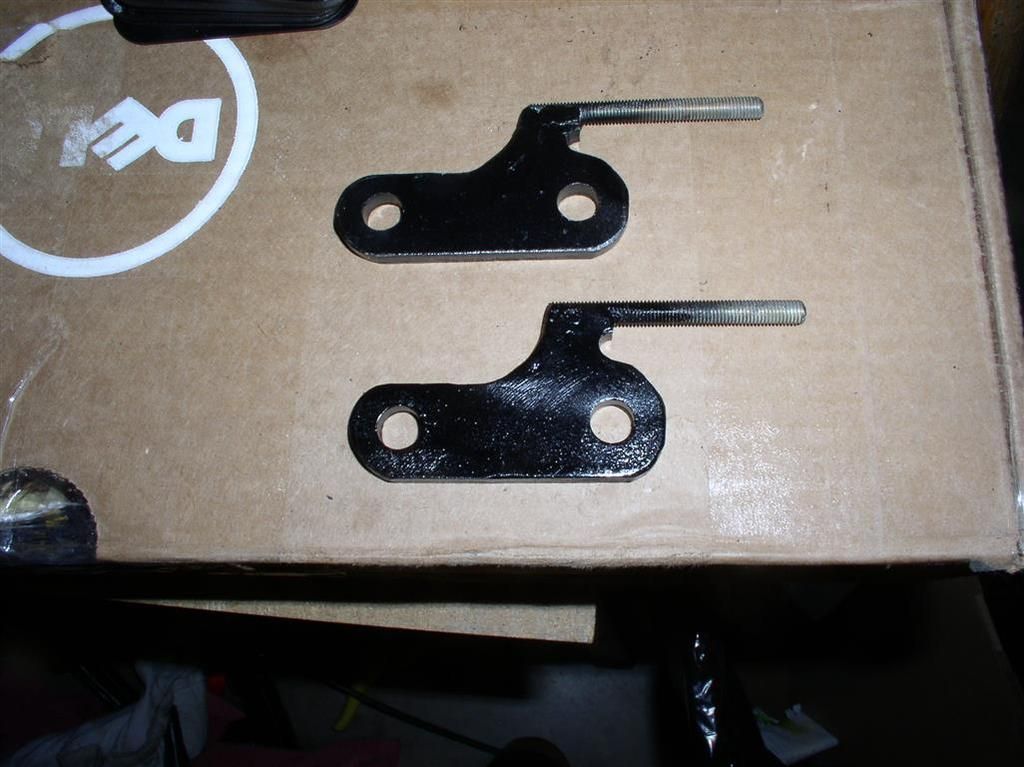
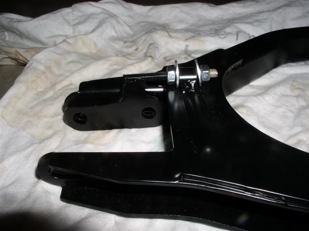
I wanted to show off my cool W-WadeCo Camber Lock System.
Other systems had been evaluated, and are very nicely made, but the main drawback is they require drilling into the Upper A-Arm to mount the "Stop Plate". This could potentially weaken it.
The engineering dept. at W-WadeCo came up with a simple design that uses a welded retaining ring on the upper A-Arm. The special Camber adjustment shim can then be used to lock the camber, as well as perform fine adjustment with the threaded shaft & nuts. As shown in the picture, the system is not tightened, that's why the washer is at an angle.
Lock Brackets
Adjustment Stop (Welded to A-Arm)
Camber Lock Assembly
Bushing
Finally, JFB had a question on getting the bushings out. Here's how Wade did it..... You gotta be careful, though!
Rocky
Other systems had been evaluated, and are very nicely made, but the main drawback is they require drilling into the Upper A-Arm to mount the "Stop Plate". This could potentially weaken it.
The engineering dept. at W-WadeCo came up with a simple design that uses a welded retaining ring on the upper A-Arm. The special Camber adjustment shim can then be used to lock the camber, as well as perform fine adjustment with the threaded shaft & nuts. As shown in the picture, the system is not tightened, that's why the washer is at an angle.
Lock Brackets

Adjustment Stop (Welded to A-Arm)

Camber Lock Assembly

Bushing
Finally, JFB had a question on getting the bushings out. Here's how Wade did it..... You gotta be careful, though!

Rocky
More reassembly... Getting closer to a reality!
See pictures in the Slideshow (above).
See pictures in the Slideshow (above).

More suspension progress.
Click on the link a couple of posts up. Pictures added to the Slideshow.
Rocky
Click on the link a couple of posts up. Pictures added to the Slideshow.
Rocky
Add Reply
Sign In To Reply