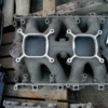
Ron this one is of special interest to you, because it's a Boss 302 manifold, a Ford experimental manifold, with an XE number cast in. It is a low rise DUAL DOMINATOR intake. Pretty bitchen. Man would that look trick in the engine bay of a Cobra, or a rat rod, with 2 big dominator carbs sittin' on top.

It looks like each venturi of the carbs feeds one cylinder each with a short direct shot. There is a plenum between the two carb mounting pads, but its hard to see how its incorporated into the design.

The picture is off ebay, apparently this manifold at one time belonged to Dyno Don.

Enjoy!

Attachments

Images (1)
  • Boss_302_XE_intake
Original Post

Replies sorted oldest to newest

YOOOOWWWW !!!! Thats a experimental piece eh ??? Thanks George !

I have this soft spot for BOSS 302's and two dominators must have been something seriuos below it.

My Cobra is an 1988 Autocraft with a 88 5.0 EFI I just havent had the balls to alter it one bit. Its all original 8k miles. I want to use the R302 in it but one project ata time jut in case I dont get the PANTERA done I got a back up for the summer. You guys are lucky in Southern CALI!

Attachments

Images (1)
  • 427_TP_2x4
Someone from the BOSS302 Forum will be on that like a big dog! Looks like someone installed the AN fitting in the center plenum to adapt it for street use (power brakes). Thanks for posting George.

ACCOBRA, looks like someone have a few mods to the top of that Tunnelport intake!
quote:
Originally posted by accobra:
...I sold it about a month ago ...


I am so jealous of the new owner. I wish I had the bucks to have made you an honest offer Ron, I'd give my eye teeth & a pair of precious other things to acquire a cammer. It's a "reliving my youth" type thing for me. I maintained one of them babies, the valves weren't so bad, the chains needed adjusted more often than the valves. Hey but no points to adjust, it had transistorized ignition!
The B302 dual dommy intake was actually an independent runner induction system that isolated each of the four barrels of modified dominator carbs as the rules allowed. In regard to that AN fitting, there is no plenum, at least in regard to the induction system. If you have a look at the auction you can see that it is crankcase ventilation. These intakes also required an offset tach.

Kelly
Panterror,

That sounds right but 2 Dominators is a LOT of gas and air. They are about 1100cfm each ! LOL An independant runners. Nice.


I know this is off the subject and a stupid question for a 3rd generation Pipefitter but can some one tell me what the sizes mean with AN fittings they come in a 4AN is that in Millimeter??

Ron
Ron, once you read this, it will not be confusing any longer, it is actually quite simple.

The AN fittings adhere to a military standard, AN meaning Army Navy.

The dash numbers refer to the OD of the steel tubing, expressed as a fraction, in which the denominator is 16:

i.e. a dash 4 is 4/16 or 1/4" OD tubing

or a dash 6 is 6/16 or 3/8" OD tubing

or a dash 8 is 8/16 or 1/2" OD tubing

Simple huh?

Your friend on the DTBB
Yes very simple thanks.... never seent tat before ... just finished a job at West Point and nothing there was as simple as that ! LOL

Kool thanks George. Hey one more question if I may ? I have to create vacumn ports on the webers, what do you think, SS tube with flare fiitings, compression fittings, AN fittings w/ SS braded line ? Also was looking for a 9 port block ? I may have to see if I can get it made in the Ind Park near my shop.

Again Thanks,

Ron
I'm not able to access ebay during the day from work, my employers internet filtering software won't allow it. So I can't see this stuff on ebay until the evening. The first pic I posted had been posted by Blizz on the Cleveland Forum, so I ripped it from there. Below are two other pictures of the manifold from ebay, one shows the bottom & the runner configuration, the other shows Don Nicholson Racing scribed on the intake near the casting number. enjoy...

Attachments

Images (1)
  • ab_3
George is going to tell you the same thing I am DT. The ports on the Boss 351 are the same as the Boss 302, and all Cleveland 4v heads.
I think what you are thinking of are the 302 Tunnelport heads. Those are round.
This manifold that we are looking at is the 69 Boss 302 Trans-Am intake. The Dominators mount sideways and you need to use an offset distributor for it.
The size of the carbs added to the problems of lack of velocity through the ports. Valley Head service (I think they later became Falconer and Dunn) solved the problem by closing down the intake ports on the heads to a little larger then the 2v 351C heads with plastic epoxy.
The result was about 425hp at about 8000rpms.
The Full ports produced maximum hp somewhere over 9000, which is around 500 rpms past the engine blow up point.
This appears to be an unported manifold, from what I see.
Last edited by panteradoug
quote:
The Full ports produced maximum hp somewhere over 9000, which

Oh man, when you said that I got all excited. Then you went on to say it would blow up. 9000 rpm motor would be so cool. It would finaly let the heads live up to their potential. You ever notice how they are saying not to bother porting 4v heads?? It is because it can already carry way more than what the engine needs. So what you need is either more cubes to feed or way more rpms. I would love the rpms but the blocks can't handle it. I think if I can just eliminate the cam, and plug the holes were the cam used to be, maybe then the block could handle the high rpms.
What you think??
Well Mr. doug, I can't keep doing this cause George will get mad at me cause by being a dummy I keep hijacking threads, but I thought of a turbine, since it is the most volumetric efficient engine out there. The problem then is coming up with a tranny that will handle the torque reduction. In other words, You can use a little tiny turbine that weighs less than 100 pounds, it would spin like 70,000 rpm. But then instead of 4:22 to one final drive ratio, you would need to do a 17:00 to one or so. You trade a little tiny motor for a huge heavy tranny. No net gain. SO I have to stay in the ball park. Sort of. Now wankles, or rotaries are appealing, but they still don't have that seal issue worked out very well. Not for an everyday car. For a full blown racer, it would be ok. But the idea of big smoke clouds following around after you, really turns me off.
quote:
Originally posted by comp2:
The engines (2) on my airplane internally spin 38,100 rpm max, produce 750hp and 2080ftlbs of tq propelling a 11,000lb airplane 300mph.

Gary

Yep, that is all true Gary, but they are too much for the car. If you reved it up and dumped the clutch on your car, just the way it sits now, with a ZF, what do you think would happen?? Yep, clutch would explode and the car wouldn't move an inch. Even if you put a big beefy clutch in, your tranny would be the next thing to explode cause the gears are trying to accelerate too fast. So you have to gear everything down so it isn't trying to go from zero to light speed in zero seconds. That is why you need bigger gears.
Frank Klepz showed us his turbine car before J Leno helped him get the workings to get it going. It is supose to be a good driving car with lot's of grunt!
http://groups.msn.com/_Secure/0dQAAAMsifyE6qBeB4lkOTHq7...=4675508135909226044

There have been a number of race car turbines which typically had transmission problems. They were usually outlawed before they ever got the bugs out:
http://128.83.80.200/mcoupe/sindy03_10.jpg

Gary
Gary, DeTom, close your eyes & imagine this:

You pull up to a stop ligh next to a Ferrari, you're in your Pantera with a turbine in the back! The Ferrari driver looks over at you in bewilderment, as you sit in your Pantera, which is sounding like a fighter jet preparing to launch down the run way. The light turns green, you open up the vanes and instantaneously whine away and vanish in the distance, before he's finished slipping the clutch in first gear.

The Ferrari pulls over to the curb, the paint on the front is blackened and scorched from your turbine's exhaust. It sits there smoldering at the curb. The owner gets out of his Ferrari, his face also blackened, his eyebrows are missing, his hair singed; he kicks the front fender in disgust, throws the keys on the ground, and starts walking.....
he, he, he ......
Actualy George, Gary Hall told me a somewhat simular story. He said he was headed down a highway out there in California. There were two F40s dicing it up with each other. Now this is a super rare car, so for two of them to be playing each other, had to be two friends who hooked up to play. Well Gary said he hammered it and caught them and left them both far behind. He said he pulled over for lunch later and here come two Ferrari f40s into the parking lot. He listened in on these two guys bench racing for awhile, then he walks over to their table and asks what kinda cars they are, and of course, they tell him they are the fastest cars in the world and all, so Gary asks them what that purple car was he saw passing them, and they said "Oh taht?" That was nothing, that was somekind of an AMerican hot rod. You could never buy cars like taht.
I love Gary Hall. He is so cool. When I grow up, I want to be like him. Big Grin
[quote]How about the shiniest 3/16" stainless tubing, which I think is 306L, plus Swagelock male connector fittings with 1/16" NPT threads?

Have your multi-port block chrome plated, or polish it on the buffer wheel.

George,

I ordered 1/8 MIPS x 1/4 tube SS adapters in SWADGLOCK I have the tube in 316SS it says .25 on it, funny the stuff we use is polished on the indside ? my luck. they were 7.10

Any ideas on a 9 port block. I have piece of 1x1 aluminum bar stock.
Ron,

I drew up a little sketch of a distribution block with some dimensions for 1/8" NPT ports.

My scanner at work is on the fritz, I'll edit this post & attach the sketch later this evening when I get home.

Minimum dimensions figure out 1.5" wide x .625" thick x 3.25" length, due to the use of 1/8" NPT & 1/4" tube. Dimensions could be reduced with 1/16" NPT & smaller tubing.

Your friend on the DTBB
George I was thinking the same but the 1/8 tappings are already in the manifold so it was easier. But I was thinking if it was possible to use tees on each side with one 3/8 line on each side to a 3/8 tee then SS hose connector and hose to the steel line to the front. Maybe I'm thinking too hard ?? LOL They make a tee with a MIPS on the bull of the tee then SL joints ?? I thought of the even distribution with seperate lines to a block.

I bought 16 of them today so we are on our way.

I found this on one of the weber sites. But I question it only becuase ... just becuase they get like 300.00 for this tube set up. Cost me 112.00

Next is the linkage, this pic shows it but not sure of how the PANTERA cable linkage mounts.

Thanks
Ron

Attachments

Images (1)
  • weber_linkage_and_vacumn_lines__1
Ron,

where do yo want the distribution block located?

at the rear of the manifold, with 8 long lines bending all around joining with it, looking like a nitrous system? Or would you prefer something less noticable, stealthy, , nestled in the middle like in your picture. I like the stealthy installation, because it keeps the tubing runs shorter.

There are several ways to go about this, you know as well as I. Some look better than others, some are easier to install, or easier to work on.

One comment about the manifold in your pic, the fittings are grouped so tightly that to get a wrench on one of the fittings in the middle of the distribution block, would require removal of the outer fitting next to it. Bad engineering in my opinion. Especially for the poor guy trying to tighten a loose middle fitting.

What are you hooking to this? Power brake? Vacuum advance? PCV?

your tubular friend on the DTBB
George ,

I was going with the theory based on the pic but have not yet layed out the block. I wanted to get the fittings to do exactly what you are tlaking about and make sure a line wrench fits between the two but wanted to keep this as discrete as possible.

Its for the Power brakes.

The PCV well have not thought of that yet, but was wondering if it could be put into the exhaust like we used to do with the race car with the flueted tapping into the collector ? Or is there a tapping in the head for an emission port ? Or maybe add another port to this snake set up? Whats your feelings ?

The vacumn advance maybe take another port off of this set up since I will not be applying the brakes and hard into the gas for power brakes and vacumn advance at the same time ? LOL

Need some technical help to bail me out here? I have plenty of tubing all sizes and fittings.

Thanks,

Ron
Vacuum from one port is enough for the PB.
If you are already drilled string the ports together with tee fittings like one would do with a fuel line, on the outside of the manifold.
The picture you show of the block is for nitrous more then anything else.
You don't want the plumbing in the center. It will be in the way of everything and will have no accessabilaty once installed on the car.
The cleveland throttle pivot will be further forward then this manifold is and will pull on the center pivot arm on the drives side.
Keep the throttle arms to the carbs to the passenger side of the pivot arm and anchor both at the same point. Keep those arms as horizontal as you can at throttle rest.
I used a tower to do that to the drivers side. Everyones linkage will be a little different.
Why don't you just buy a Pantera linkage set from a vendor as a starting point?
Last edited by panteradoug
Panteradoug,

The picture I was told by Inglese is there vacumn kit. my intake was previuosly drilled exactly like the pic. What we use it for is another thing. I wondered if I could use it for PVC, power brakes, and vacumn advance as George and I were disucssing. I prefer in the middle down low as possible.

I guess I could use this for pcv and vacumn advance and attach power brakes to one port or can I use this for all 3. Its a common vacumn manifold like on a stock intake block with 3 connections. this will enable it to be drawn evenly ?

The pic cant be nitrous there are no injectors and there would be double line sets for fuel and gas ? NO ?

The post that rises from the manifold on mine I can thread the lines any route to avoid the linkage and down low exactly like the pic.

I asked first starting with Hall because it was their intake, they blew me off. Then inglese but they want my underware size on some big long application .. LOL .. Great idea I'll see if PI sells it. I'm a little slow on this stuff. Its a learning curve.

Ron
Ron,

Considering the small size of the tubing, I would advise you to run 2 separate blocks, one up front for those 4 cylinders, one at the rear for those 4 cylinders. run the power bakes & vacuum advance from the forward block, run the pcv system from the rearward block. Don't mix the PCV with the vacuum accessories.

I advise this because I would suspect that the PCV system would decrease the vacuum in the block, which would screw up the brake booster & vacuum advance functions.

Plumbing it this way, if you drill & position each block in the middle of the 4 runners, you could plumb it with short straight runs of tubing, no tube bending necessary. Makes it easy!

Am I clear, or do I need to draw it up?

wadda ya think?
No need to draw it, I'm crystal clear on what your saying the theory on what goes where is my only question. I can bend and plumb anything with instrumentation .. but still on the fence. I thought the method was to keep the draw even. the power brakes and vacumn advance could go off the 8 port block and the spagetti system. Or I can opt to eliminate the vacumn advance and away goes that problem. But the PCV still puzzles me.

In the race car we used to use flueted tubes in the collector headers ? Is there any other option for the PCV. Or put the PCV thru the spagetti and take the brakes off one runner ? I think it needs to be even draw ?

Sorry just a little slow on this subject maybe its too much spec work and working with engineers that bogs me down.

Ron
Post
×
×
×
×
Link copied to your clipboard.
×