

I'm starting this post for guys and gals whose goal is to build an ultra high horsepower engine ... 500 BHP or more ... for the street. The focus is upon custom engines using blocks from the smaller Ford push-rod V8s as their foundation, i.e. the 289/302/351W/351C. The small block Ford is the second most popular engine in the aftermarket industry, parts abound, prices are good, obsolescence is not an issue as it is with certain 351C specific parts.
Custom engines can be defined as those using aftermarket reciprocating assemblies and/or aftermarket cylinder heads.
I'll start by sharing "basic" information about two general topics, i.e. making horsepower and making an engine durable. I'll propose an engine project at the end. If you want to discuss 750 horsepower street engines or 460 cubic inch strokers, it is welcome ... that's the point of this topic. There are lots of members with very powerful engines whom I hope are willing to share with you what they've learned regarding this topic. If this subject is important to YOU, if you feel you have information to add to this topic, or if you have questions, please contribute to the thread.
Making Horsepower - The Big Picture
There are three aspects to making horsepower, listed as outline headings below. Use them to develop a plan for a high output engine; then acquire the parts complementary to your performance goal and complementary to each other. Outline entries regarding the choice of parts have been emboldened to show how those choices fit into the "Big Picture". Those are the first steps. However, if all we do after acquiring the parts is bolt them together we'll leave a lot of horsepower on the table. To achieve the full potential from an engine requires attention to detail, precision machine work, and many hours of test assembly, measurement, disassembly, revision, and reassembly ... sometimes over and over.
Item 1: Maximize Thermal Efficiency - Top Importance
- Choose modern "thin" piston rings with the guidance of a ring manufacturer’s representative. Maximize piston ring sealing. All of the time and budget lavished upon getting the rings to seal as well as possible shall maximize the benefit of everything else you do to make more horsepower. Bore the cylinders with "head plates" torqued in place, and with the main bearing caps torqued in place. Your machinist should follow the honing procedure recommended by the ring manufacturer and finish the cylinders walls to the surface roughness and cross-hatch angle recommended by the ring manufacturer. Hand fit the rings to each cylinder.
- Choose cylinder heads with shallow, high swirl (Weslake) combustion chambers.
- Static compression ratio should be set as high as possible while allowing full ignition advance with the fuel octane the engine shall be operated on. This is limited by the cylinder head design and camshaft timing (dynamic compression is impacted by the timing of when the intake valve closes).
- Set deck clearance in the range of 0.005" to 0.0035" (that is 1cc through 7cc based on a 4" bore).
- Equalize the compression ratio in all 8 cylinders, this requires 3 steps. Deck the block, equalize the deck height of each piston and rod combination in their associated bore, and equalize the combustion chamber volumes.
- The ignition must be in perfect working order. The ignition must produce a properly strong spark across a wide plug gap at all rpm within its power band, this is accomplished by properly charging the coil at all rpm (known as dynamic dwell). The ignition must be timed properly, the timing should operate with as much precision as possible, the timing should operate consistently from cylinder to cylinder, and the centrifugal advance must work smoothly.
- The fuel metering system (carburetion or fuel injection) must be properly calibrated for all loads and rpm.
Item 2: Minimize Frictional Power Losses
- Modern thin rings mentioned above not only seal better, they reduce frictional horsepower losses as well, by virtue of narrower width and lower tension.
- Index the boring machine to the crankshaft centerline during the boring process. This minimizes thrust forces on the cylinder walls resulting from bores which are canted left or right, or canted fore or aft.
- Rod/stroke ratios between 1.6:1 and 1.7:1 also minimize thrust forces on the cylinder walls without impacting acceleration.
- Minimizing compression height (placing the wrist pin bore as high as possible in the piston) lightens the piston and minimizes piston rocking in the bore.
- Choose a crankshaft having a stroke (crank arm leverage) matched to the weight of your vehicle and the traction of its tires, and/or to the piston speed you want the motor to operate at. Strokes which are longer than necessary increase friction unnecessarily. They drag the rings up and down the bore more, the counter-weights get larger, windage increases, and rod angularity increases.
- Minimize oil drag on the crankshaft and pistons by using a windage tray and scraper, and by using bearing clearances which are no greater than necessary.
- The crankshaft, laying in a lightly oiled set of new main bearings and with the caps torqued in place, should turn by hand with minimal effort. If not this indicates either the crank needs straightening or the main bearing saddles need line boring.
- Utilize a fully counter-weighted crankshaft ($$$) if its within the budget.
- Dynamically balance the reciprocating assembly.
Item 3: Maximize Volumetric Efficiency
- Piston Speed Makes Power! The engine’s power band should operate within a range of mean piston speed which is as high as you find acceptable; within the limits imposed by concerns for short block wear, crank arm leverage and budget. Peak horsepower should occur at the highest piston speed possible within that same range of mean piston speeds. The engine’s rev limit should occur at the top end of the same range of mean piston speed.
- Choose a camshaft with parameters (duration, overlap, EVO, IVC) which shall operate the engine over the power band dictated by the range of mean piston speed you've selected. The cam should open the valves as fast and as high as possible within the valve train wear rate limits and budget you find acceptable.
- Choose valve train components which complement the camshaft and which complement your engine speed and durability goals.
- Optimize the rocker arm geometry.
- Choose cylinder heads having ports complementary to the displacement and power band of the engine, and complementary to your power goals. Maximize intake and exhaust port performance via porting and valve seat profiling.
- Choose an induction system having design and performance complementing the cylinder heads and the application.
- Supply cold air to the induction system.
- Choose an exhaust system having design and performance complementing the cylinder heads and the application.
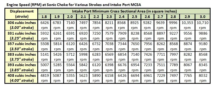
Mean Piston Speed
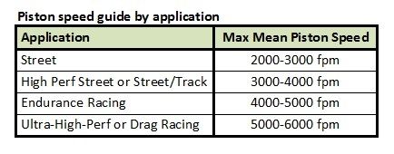
Piston speed makes power! Piston speed is the impetus of intake and exhaust gas velocity. BUT higher piston speed increases the destructive forces the reciprocating assembly and the cylinder walls are subjected to. Of course a piston does not move at a constant speed, so engine designers usually refer to the data in the simplest terms which is "mean (or average) piston speed" as opposed to "peak piston speed". There are some fairly well accepted guidelines for mean piston speed (expressed in feet per minute) based on application, I've listed them in the chart below.
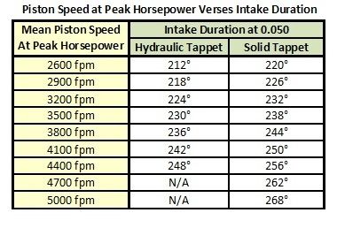
There's a lot to learn from the charts I've included below. They reveal that piston speed is raised or lowered with changes in either power band (engine speed) or stroke, and an engine with a 4.00" stroke operating at 6000 rpm is subjecting its parts to the same wear as an engine with a 3.50" stroke at 6857 rpm. 4000 fpm is at the high end of the recommended range for a high performance street engine and the low end of the recommended range for a road race engine. It seems to "safely" push the limit for durability without spending large amounts of additional money.

Crank Arm Leverage
Crank Arm Leverage is a concern for street cars, especially if they aren't equipped with traction control, due to the traction limits of street tires. It’s valuable to consider how controllable traction shall be, how easy it shall be to accelerate WFO while keeping the tires "hooked-up". The opposite side of that coin is how easy it shall be to spin the tires. If the car is to be driven in less than perfect weather, on wet or icy pavement, that consideration is even more important. Lighter cars will hook-up better with shorter strokes; heavier cars will hook-up with longer strokes that would overwhelm the traction limits of a lighter car.
Some will argue traction is controlled by the right foot, i.e. its up to the driver to feather the accelerator pedal "just right" in every situation. People who say that are belittling the subject. Too much "crank arm leverage" can be defined as a situation wherein the accelerator pedal shall be too sensitive for even a good driver to feather in every situation, too easy to jab a little too much and loose traction at the rear of the car. This is not so much a problem in a straight line (drag racing) on dry pavement, but it has proven to be a problem on wet pavement, it has proven to be a problem at car shows in which the cars are parked on grass, and it is a possibly deadly situation in corners. This is more of a concern for people who shall race their cars on street tires and people who drive their cars regularly in all sorts of traffic or all sorts of weather; and less of a concern for people who cruise their cars on sunny afternoons.
The crank arm leverage of a long stroke crankshaft achieves two things:
- It achieves higher piston speed at relatively lower pm. This makes higher engine output achievable at lower rpm.
- It endows the engine with an abundance of low rpm “pep” by virtue of crank arm leverage (low rpm torque).
But a huge amount of “crank arm leverage” (low rpm torque) breaks street tires loose more easily than cranks with shorter strokes; this problem worsens as the weight of the vehicle decreases. Sports cars and performance street cars (like Mustangs) tend to be fairly light weight. It’s appropriate to question then if a sledge hammer abundance of crank arm leverage and low rpm torque is the goal, or is the goal in truth “low rpm pep” similar to a modern fuel injected engine? "Low rpm pep" can be achieved without installing a long stroke crankshaft.
Alternative Methods for Achieving Low RPM Pep
Everybody loved the “low rpm pep” of Ford’s 5.0 HO V8 (introduced in 1986), yet the engine only made 215 net horsepower and only had a 3.00” stroke crankshaft! People thought of the engine as a “torque monster”. Obviously the engine’s short stroke WAS NOT the source of its “low rpm pep”. The pep was derived from a combination of low-rpm tuned cylinder heads, a long runner intake manifold, and individual port fuel injection. It was the type of pep older people hadn’t experienced since 1970/1971, when Detroit and Dearborn lowered the compression ratio of their engines and recalibrated their engines for improved emissions performance. It was also more pep than younger drivers had previously experienced, they were accustomed to cars equipped with small displacement engines, many still fueled by carburetors, tuned for emissions compliance and fuel economy.
The first point to make then, the “pep” of any older engine can be improved by raising the static compression ratio and installing a carburetor tuned for “street performance”. Lower axle gearing (numerically higher) also improves the feeling of “pep” in the way the engine performs at low rpm. However, people who are used to the power delivery of modern fuel injected engines may still be disappointed by the “pep” of any carbureted engine. It is difficult for a carbureted engine to compete with a fuel injected engine in terms of “low-rpm pep”. It is typical for throttle body fuel injected engines to make about 15% more torque at low rpm compared to similar engines equipped with carburetors by virtue of improved fuel atomization. Long runner port-fuel injection improves that pep even more by virtue of the acoustic tuning of the long intake manifold runners.
Thus people may find the power delivery (i.e. “low rpm pep”) of any carbureted engine more satisfying by switching to a carburetor equipped with “annular booster venturis” which atomize fuel better. Throttle body fuel injection will improve that pep further yet, beyond what can be accomplished with any carburetor. Long runner port-fuel injection shall improve “pep” further still. All of these improvements in the engine’s low rpm “pep” can be accomplished without resorting to a long stroke crankshaft.
The Alternative Method for Achieving Higher Piston Speed
There is also another means for obtaining higher piston speed (and the potential for higher output) without increasing crank arm leverage. That is to extend the upper rpm range of an engine’s power band by raising the rpm over which the engine operates or (preferable for a street car) by widening the rpm over which the engine operates. Keep in mind, regardless of engine rpm, when the piston speeds are the same the wear upon the reciprocating assembly and the cylinder walls is no different. Raising the power band may require replacement of certain valve train components to enable the valve train to remain stable at higher rpm. Whether or not this is necessary shall depend upon the acceleration rate of the camshaft lobes and which valve train components are already in use. Hydraulic tappets may still be OK in some applications, but solid tappets become a better idea above 6500 rpm. However, stress upon the block’s main bearing structure may potentially increase at higher rpm (it depends upon the crankshaft). So a dynamically balanced crankshaft and a highly effective crankshaft damper become more of a financial necessity. Lower final drive gearing is usually the final touch necessary to prepare a drive train for operating at higher engine speeds (a Pantera’s factory gearing is adequate).
Some enthusiasts prefer lower gearing and a shorter crankshaft stroke over higher gearing and a longer crankshaft stroke. It is not my intention to argue in favor of one choice or the other. It is my hope to provoke thought on the subject, and that after careful consideration each person makes their own choices.
Short Block Durability
The engine of a "show car" does not require having the same amount of durability built-into it as the engine of a car that will be "driven hard" by the owner. The longevity of the engine is going to depend upon how often the car is driven, how many miles per year are put on the car, and how hard the car is driven. Road racing, circuit racing, or endurance racing are tougher on an engine than cruising, and even tougher than drag racing. If the car shall be raced, even just once a year, that's the application the engine must be capable of enduring.
There are three concerns regarding engine durability, listed as outline headings below. Engine stress can be dealt with in two ways:
- By making parts stronger thus avoiding failure because the parts are better able to withstand the stresses they are subjected to.
- By minimizing the stress and destructive forces in the first place.
The decision to be made by the assembler of a custom engine is which is the best course of action, or if any action is needed at all. Develop a plan for your high output engine's durability; use your plan as a guide as you acquire parts for the engine.
Item 1: Main Bearing Support Structure Stress

No matter how piston speed is achieved, via increasing the stroke of the crankshaft or via revving an engine at high rpm, all other things being equal, equal piston speed stresses the components in the next two topics equally.
Item 2: Reciprocating Assembly Stress
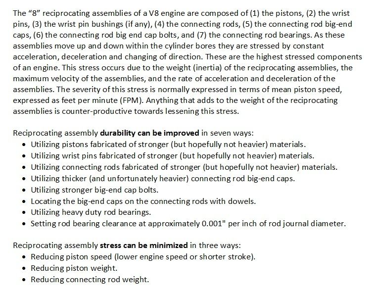
Item 3: Cylinder Wall & Piston Skirt Stress

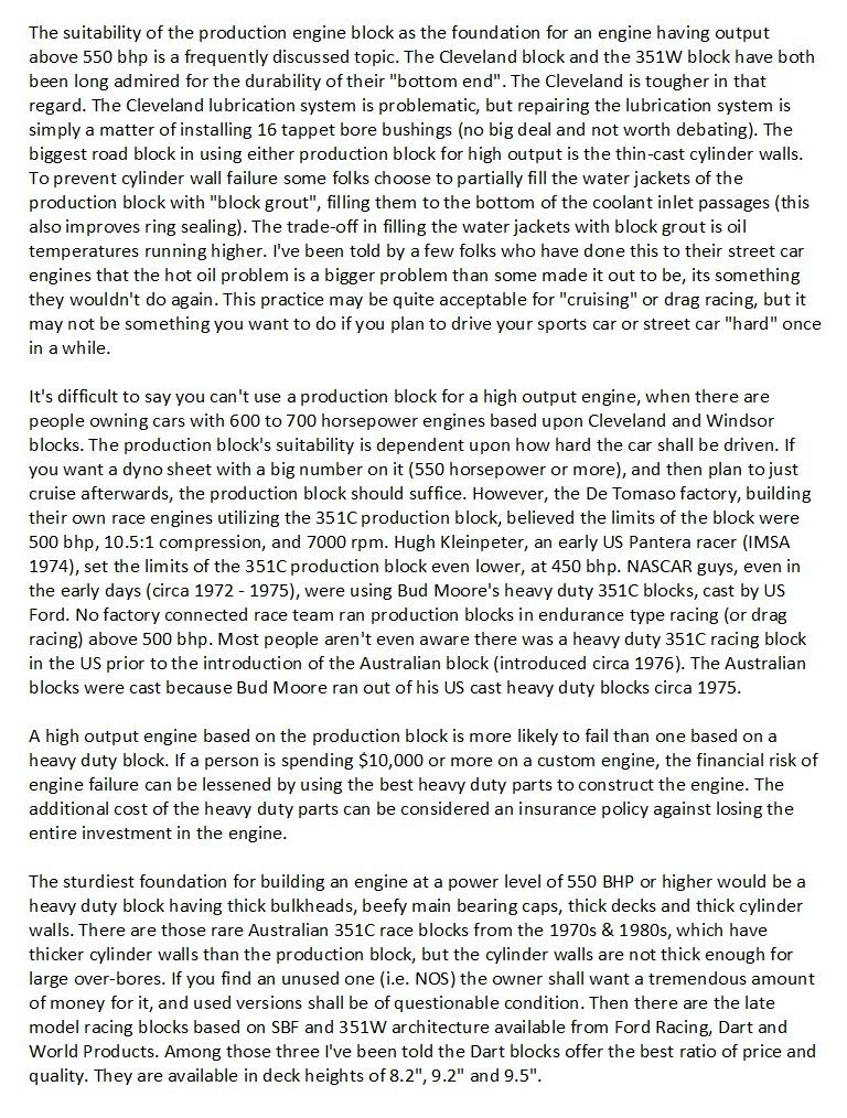
Block
8.2" Deck Height Blocks
The little 8.2" deck height Ford V8 equipped with "hybrid" cylinder heads (i.e. a Boss 302) is light, compact, and powerful. I think those are important considerations for a sports car or a lightweight car like a Mustang. One possible "custom" short block combination that is compact and light could be based on the 8.2 deck height block and a 3.25" stroke crankshaft. A SBF with a 3.25" stroke shall usually displace 327 to 331 cubic inches (4.000" to 4.030" bore). But with a 4.100" bore the little 8.2 deck Ford would displace 343 cubic inches.
3.25" stroke would be my limit for the 8.2" deck height block due to 2 considerations:
- because that's all the stroke you can get and keep the wrist pin out of the oil ring groove
- because it is the longest stroke with a decent rod/stroke ratio (5.3" rod & 3.25" stroke = 1.63:1 rod/stroke ratio)
Other considerations, piston speed and crank arm leverage, are both very good at that stroke too. A small block Ford (8.2" deck height) can achieve the same output as its bigger cousins, its a matter of piston speed. As you shall soon learn an engine with 3.25" stroke puts no more stress on the reciprocating assembly or cylinder walls at 7300 rpm than a 408 stroker operating at 6000 rpm. The challenge is to rethink crankshaft stroke. Think of it not in terms of cubic inches, rather in terms of piston speed and crank arm leverage.
9.2" and 9.5" Deck Height Blocks
If I were building an engine displacing more than 343 cubic inches, I'd opt for a heavy duty Dart racing block having 9.2 deck height or 9.5 deck height, whichever size had the most readily available headers and other parts for the application (Pantera or which ever chassis the engine was going into). The 9.2" Dart block, or a similar block from Ford Racing, makes the most sense for owners of Cleveland powered cars at least until the Buttermore 351C block becomes readily available. In general the 9.2" deck height favors 351C applications and the 9.5" deck height favors 351W applications. Although you may discover that "Clevor" intake manifolds, designed for 2V Cleveland heads on a Windsor block, are designed for 9.5" deck heights and must be milled to fit a 9.2" block.
With a 9.2 or 9.5 block the best crank choices shall be 3.400" (fully counter weighted NASCAR parts), 3.500" (factory stroke) or 3.75". If you must have more than 357 cubic inches the 3.75" stroke crankshaft is the best choice (377 - 383 cubic inches). My opinion is based upon these 3 considerations:
- any more stroke than that has too much piston speed.
- any more stroke than that has too much crank arm leverage for street tires.
- any more stroke than that has too little rod/stroke ratio.
If you plan to drive your Pantera "hard" from time to time then engine durability is directly tied to piston speed. But if all you're going to do is cruise your car in good weather then you'll never stress the engine and concerns for crank arm leverage most likely won't concern you either.
If your plans include an engine displacing more than 383 cubic inches a Dart or Ford Racing block has advantages for you. They can be bored much larger than the production blocks or the Australian 351C race block, some are rated for bores of 4.165" and even 4.185". The 9.5" deck height versions can be stroked a bit more than a 9.2" Cleveland block too. The thick cylinder walls of a heavy duty Dart (or Ford Racing) block make more sense for use with rod/stroke ratios less than 1.6:1 as well! Whereas the acceptable limit of a 351C production block is 408 cubic inches, versions of the Dart and Ford Racing blocks are bored and stroked to 427 cubic inches, 434 cubic inches, some folks have bored and stroked them all the way to 460 cubic inches.
Crankshaft
The factory 351C crankshaft was cast from high nodularity iron alloy. The factory crankshaft was a very strong crankshaft, very high quality. They have been used for 8,500 rpm NASCAR racing and 10,000 rpm Pro-Stock and Super-Stock drag racing. But its manufacture was constrained by the limitations of high volume mass production, including:
- It was partially counter-weighted (6 counter weights instead of 8 counter weights). This heavily loads the second and fourth main bearings at high rpm.
- It was externally balanced. Internally balancing an iron crankshaft is difficult because iron is less dense than steel. External balance heavily loads the first and fifth main bearings however.
- It was designed for maximum bob-weight instead of being designed for minimum bearing load. This also heavily loads the second and fourth main bearings, but it reduces the "out-of-balance" loading on the first and fifth main bearings.
Aftermarket Choices
- those cast from iron, partially counter-weighted
- those cast from steel, partially counter-weighted
- those forged from steel, partially counter-weighted
- those forged from steel, fully counter-weighted
- those machined from a billet of steel, fully counter-weighted
Counter Weights
- Production crankshafts, and aftermarket crankshafts manufactured in China, are partially counter-weighted (6 counter weights)
- Partially counter-weighted crankshafts increase the loading of the 2nd and 4th main bearings, bearing journals, and bulkheads at high rpm
- a fully counter-weighted crankshaft (8 counter-weights) is very expensive to manufacture, and always manufactured domestically.
- fully counter-weighted crankshafts reduce the "loading" of the second and fourth main bearings and bulkheads during ultra-high rpm operation.
- The bending deflection across the center main at high loadings and high engine speeds causes measurable power losses in engines equipped with partially counter-weighted crankshafts. Therefore the benefits of a fully counter-weighted crankshaft are less stress on the engine block and the reduction of power losses, i.e. an increase in power output!
- fully counter weighted crankshafts are the only type of crankshaft that should be utilized in an engine that shall be operated at 8000 rpm or above.
Internal Balance verses External Balance
- It is difficult for a manufacturer to internally balance a cast iron crankshaft because iron is less dense (less heavy) than steel. There is not enough mass to internally balance a cast iron crankshaft.
- External balance increases the loading on bearings #1 and #5
- Internally balancing an iron crankshaft requires using "ingots" of "Mallory Metal" which are very expensive
- Only engines operated at constant high rpm (usually race engines) "need" to be internally balanced, because at high rpm the external balance is trying to break-off those parts of the crankshaft which hang-out in front of the first main bearing and behind the fifth main bearing.
- If you are ordering a new steel crankshaft, a new crankshaft damper, and a new flywheel (or flex plate) all at the same time, it makes sense to order all of them designed for internal balance. This is a smoother operating way to go, and definitely less loading on the first and fifth main bearings.
Quality of Construction
- All of the inexpensive crankshafts found in stroker kits are sourced from China, but they are machined in the US
- The machinists and mechanics who assemble engines for a living consider the stroker crankshafts sold by Scat to be the only crankshafts with machine work of reliable precision; i.e. the journal roundness, taper and balance of each crankshaft is machined within acceptable limits.
- The stroker crankshafts sold by Eagle are considered the second best, but Eagle's precision is not as reliable as that of Scat's.
- The machine work of stroker crankshafts (journal dimensions, taper, roundness, etc.) should be checked before assembly no matter whose kit you purchase.
- A step-up in quality above the stroker crankshafts are the mid-price "sportsman" style forged steel racing crankshafts. Sportsman cranks are designed from their inception for racing, but they are partially counter weighted to reduce costs. They are machined in the US by reputable companies such as Callies and Bryant. A sportsman crankshaft alone costs as much as an entire stroker kit.
- Since a sportsman crank is forged from steel and designed for racing, it should come from the manufacturer internally balanced. However like the production crankshaft a sportsman crank is only partially counter-weighted. So before you purchase one shop around, talk to the engineers who designed them, and make sure you purchase one that has been designed to minimize bearing loads. Since it is made of steel there is no reason for it to have been designed to maximize bob-weight. If it were thus designed, it would load the second and fourth main bearings and bulkheads during ultra-high rpm operation more than necessary.
- Some sportsman crankshafts also offer improved rod bearing lubrication passages, which is another topic to discuss with the crankshaft's engineers before you make your choice.
- A sportsman crankshaft is my minimum recommendation.
Stroker Kit Info
- All other things being equal, when installing a "stroker" crank in an engine the increased stroke (crank arm leverage) increases the engine's torque but the horsepower remains the same, the torque curve and peak horsepower simply occur at lower rpm (but the same piston speed as before the change). To increase horsepower the engine will also need a "bigger" camshaft (more intake duration) to "bump" peak horsepower to higher rpm.
- Stroker kits usually decrease the rod/stroke ratio thereby increasing the piston thrust forces bearing against cylinder walls. Full round skirt pistons (endurance racing pistons) help distribute those forces over a wider area of the cylinder wall and are effective at preventing the failure of thin-cast cylinder walls. Yet none of the stroker kits offer full round skirt pistons, they offer pistons having the less expensive slipper style skirts.
- Most (not all) 351C stroker kit crankshafts are actually 351W crankshafts with 351C sized main bearing journals. To use one in a 351C block requires a special camshaft timing set designed for that application and a spacer for the crankshaft mounted timing gear.
- One issue you may run into with longer strokes is the connecting rod big-ends hitting the bottoms of the cylinders, requiring the cylinder bottoms to be notched for clearance
- Another issue you may run into with longer strokes is the pistons being pulled too far out of the bores at BDC. This is normally the limiting factor to how much stroke is possible with these SBF/Cleveland engines.
Wrist Pin Height
It is beneficial to place the wrist pin bore as high in the piston as possible. Doing so results in a lighter piston and it reduces piston rocking within the cylinder bore. But intersecting the oil ring groove with the wrist pin bore is placing it TOO HIGH. That is a condition avoided by the engineers who design engines. The oil ring groove has a function, controlling the oil wiped on or off the cylinder wall. The wrist pin bore has a separate function, transmitting the force of the piston and the motion of the crankshaft. Those functions interfere when the oil ring groove and wrist pin bore intersect. This condition only occurs when aftermarket stroker kits push the limits of an engine's dimensions. In the past this condition has resulted in excessive oil burning. Today there are solutions for the resultant oil burning, it can be lessened by second ring designs or by adding a special dimpled rail support below the three-piece oil ring. However, the existence of a solution for oil burning does not make the intersection of the wrist pin bore and oil ring groove "good engineering".
Rod Length to Stroke Ratio
A rod length to stroke ratio within the range of 1.6:1 to 1.7:1 is the best compromise for street engines AND 7000 to 8000 rpm race engines. Less than 1.6:1 increases the thrust forces bearing against the cylinder walls exponentially; this is not a wise choice for thin-wall production blocks, and in general it increases operating frictional power losses. The production 351C had 1.65:1 rod/stroke ratio. The production 351W had 1.7:1 rod/stroke ratio. In the 1960s Ford testing indicated that 1.7:1 rod/stroke ratio provided the least cylinder wall thrust force without impacting an engine's acceleration. Ratios greater than 1.7:1 resulted in slower acceleration. At ratios of 1.8:1 or more intake system "lag" becomes a problem, requiring intake ports that are smaller than ideal.
Cleveland Piston
The Cleveland's big intake valve is located very close to the cylinder wall, canted in such a way that it's outer edge is almost flush with the deck. The fly-cut in the piston dome for intake valve clearance results in a big notch in the piston's side, extending downward about 1/4" from the top. Due to this notch the ring package must be located about 1/4" further below the piston dome than it is in other engines ... and the piston's skirt is about 1/4" longer too. This impacts 351C stroker kits in two ways:
- The wrist pin bore intersects the oil ring groove with shorter stroke and connecting rod combinations than it would if the ring package were higher.
- The piston skirt is pulled out of the bore at BDC sooner or further than it would if the piston skirt were shorter.
In-line valve style SBF cylinder heads, and certain Ford Racing cylinder heads (Yates C3, C3H and SC1) do not have canted valves. A piston designed for those heads does not have a notch in the side, thus allowing the ring package to be located higher, nearer the top of the piston. Utilizing those heads gives a person putting together a stroker engine some leeway:
- The wrist pin bore can be moved up to 1/4" higher before intersecting the oil ring groove. This may alleviate the intersection of a wrist pin bore and oil ring groove
- Moving the wrist pin bore 1/4" higher would allow a longer connecting rod and a better rod/stroke ratio
- Moving the ring package AND the wrist pin bore higher would allow a shorter and lighter piston
- A higher wrist pin bore would reduce piston rocking in the cylinder bore
- A shorter piston (about 1/4" shorter) would allow a longer crankshaft stroke before the piston skirt is pulled out of the bore at BDC.
Camshaft and Valve Train
If you're seeking very high output, a solid roller tappet camshaft shall offer the greatest contribution to your project. Street roller lobes are a compromise between performance and longevity, Comp Cam's street roller lobes have 0.0586" to 0.643" "net" valve lift (1.73:1 rocker ratio and 0.020" lash). Of course if valve train longevity isn't a concern, lobes with even higher lift and faster ramps may suit your needs.
The longevity of a street roller valve train has been made possible mostly due to the availability of solid roller tappets rolling on bushings instead of needle bearings and featuring forced lubrication instead of splash lubrication. At this point the Isky solid roller tappets #3972-RHEZ seem like a good choice.
If you're using the 351C production block or the Australian 351C racing block install tappet bore bushings having 0.062” orifices. The tappet bore bushings shall make the block and lubrication system compatible with any roller tappet you stuff into it. A do-it-yourself installation kit is available from Wydendorf Machine.
Manley Nextek #221432 dual valve springs plus damper (1.53” diameter, 1.90” installed height, 150 lbs. seated force, 435 pounds per inch spring rate, 0.630” max. lift, 0.730” coil bind) appear to be a good choice for street roller cams up to 0.630" net lift. These springs are compatible with the highest lift Comp Cams street roller lobes "IF" 1.7:1 ratio rocker arms are utilized.
A steel distributor drive gear for steel roller cam cores is a necessity (never utilize a bronze gear). They are available from Crane Cams and Ford Racing.
A lobe design like that of a solid street roller is "hotter" than racing cams were at one time. The best possible rocker arms for such a "demanding" valve train are T&D Machine individual shaft mount rocker arms (#7200 for Cleveland heads). The rocker arms are available made from steel for the ultimate in longevity, i.e. for guys who drive their cars a lot. If you don't plan to put many miles on the engine the same T&D rockers made from aluminum shall suffice. They are available in many rocker ratios, and you can mix and match intake ratios and exhaust ratios to tailor valve lift. Yella Terra Platinum rockers are an even less expensive substitute (YT6321 for Cleveland heads). The engine shall also need 3/8" push rods manufactured from 0.080" wall thickness seamless chromoly tubing.
Induction and Exhaust
The effort and financial investment put into the induction and exhaust systems impacts an engine’s potential output. The engine cannot make as much “peak” horsepower with a single four barrel carburetor as it can with long runner fuel injection induction, individual runner induction, forced induction, etc. Of equal importance to the show-car enthusiasts, "wild" induction systems look better too.
To make 550 BHP or more with a single 4 barrel carburetor is going to require a carburetor rated at 850 to 1050 cfm, depending upon the intake manifold design. This is at the high end of the range of Holley 4150 carburetors, and also within the range of Holley Dominator carburetors.
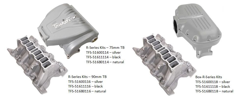
One of the Trick Flow fuel injection manifolds below are my recommendation for a naturally aspirated induction system. The Box-R induction system has the highest power potential of the two, it is an individual runner type induction. The 8 individual runners draw air from a common plenum box, engine speed is controlled by 1 throttle body on the inlet of the plenum box instead of 8 individual throttle bodies. There are advantages to doing it this way ... once the air enters an individual runner there is no butterfly or booster in the air path to restrict air flow or to cause turbulence. This is how they have done it in Formula 1 for decades, this is also the concept behind modern performance street car induction systems. The Box-R manifold is obviously not going to fit under a Pantera engine screen, but neither does a NASCAR style high rise manifold with a Holley carburetor on top, or 48IDA Weber carburetors.
The headers should have primaries with tube ID that is 110% the size of the exhaust valve, normally 1-3/4" for most of the heads you'll consider using. Collectors should be in the 3-1/2" range. The exhaust system behind the headers should be as short as possible, it should be composed of 3" tubing if possible, but I acknowledge its hard to fit tubing greater than 2-1/2" diameter in a Pantera. Front engine cars should have an "x-type" cross-over between the intermediate pipes if possible. Mufflers should obviously be low back pressure designs, 3" inlet and outlet if they're mated to 3" intermediate pipes. Panteras will usually make do with 2-1/2" inlet and dual outlet style mufflers.
Cylinder Head
A cylinder head's air flow throughout the entire range of valve opening is important, not just the peak number. A piston descending on the intake stroke reaches maximum velocity at about 70° ATDC, yet the intake valve is not fully open until about 105° ATDC. In fact the piston begins decelerating at about 110° ATDC, just 5° beyond maximum valve opening! The more air flow the cylinder head can provide at 70° ATDC (before the intake valve is fully open) the better. A similar condition exists in the exhaust system too.
A "naturally aspirated" street engine's horsepower output is quite often equivalent to twice the intake port's "average air flow" in CFM; i.e. 250 CFM average air flow would indicate 500 BHP potential. Of course "average air flow" is impacted by the distance the camshaft lifts the valves off their seats. For street cams lifting the valves 0.600" off their seats at max-lift, air flow at 0.400" shall be in the ball park of the port's average air flow. When you're judging cylinder heads based on air flow data pay closer attention to those 0.400" air flow numbers.
The cam's you are likely to be using shall lift the valves 0.600" to 0.650" off their seats, so the amount of air flow at 0.700" is of no consequence unless the same port which flows well at 0.700" also flows well at 0.400". High ports always flow better than lower ports at high valve lift, but the best high ports flow better at ALL valve lifts. The intake ports which perform best at low valve lift are usually those which have the least shrouding and the best blending on either side of the valve seat. Recessed valves kill low lift flow. For any given amount of valve lift a larger diameter valve exposes more "curtain area" than a smaller diameter valve ... however if a valve is too big shrouding may spoil those advantages, especially at low lift. Also remember the combustion chamber is at least half of the power equation.
There are lots of cylinder head choices for making high output. Modern cylinder heads having small valve angles similar to the 351C usually offer excellent high swirl combustion chamber designs, and in some cases higher ports. Although the Cleveland's shallow combustion chamber performs very well, high swirl combustion chambers improve upon the Cleveland design and manage to perform even better (improved thermal efficiency); air flow performance (volumetric efficiency) is also improved by unshrouding the valves and blending the valve seats into the combustion chamber better.
A little historic information (trivia?), it was popular decades back to refer to high swirl combustion chambers as "Yates" chambers, but that combustion chamber architecture was actually designed in the 1950s by a chap from the UK named Harry Weslake. Robert Yates simply applied that architecture to his Ford racing heads in the late 1980s.
The iron 351C 4V heads are no dogs in terms of performance, they can support up to 750 BHP. But heads known to be worth more "bolt-on" power equate to making that power without the need of a more radical camshaft and valve train. As an example, if my 351C 4V engine makes 430 BHP with un-ported iron 4V heads, bolting on a set of Scott Cook's heads (which are CNC ported out-of-the-box) and his intake manifold immediately raises the power of the engine to 500 BHP with no other changes. Of course porting the iron 4V heads would increase the engine's output too, but not to the same extent as bolting-on Scott's cylinder heads.
Among "canted-valve" cylinder head choices are "2V Cleveland heads" available from Edelbrock, Trick Flow, and the Australian manufacturers CHI and AFD. The 2V heads have the lowest intake port height of the canted valve heads, the ports are about the same height as the ports of the SBF style heads. CHI, AFD and Scott Cook Motorsports (the Australian trio) also offer "stuffed port 4V heads" that have 4V height intake ports (or higher) in which the ports floors are filled (no ramp in the floor) giving the ports a more constant cross-section and shape, and the appearance of a smaller port. The ports of 4V heads were originally 1/2" higher than 2V head ports, but the ports of the CHI heads are even higher than that. CHI also offers a version of their cylinder head with ports flared open at their inlet in order to mate with manifolds designed for production iron 4V heads.
The early Ford SVO racing heads (A3, B351, C302) were also canted valve heads, fully compatible with Cleveland valve train parts. Those heads have the same quench combustion chambers as the factory iron heads. The intake port height was raised in small steps with each version of the head. After the C302 head Ford Racing went through a phase wherein the valves were not side canted (Yates C3, C3H, SC1). These heads are usually referred to as "Yates heads". The Yates C3 heads featured increased intake port height, the combustion chambers were the first to feature high swirl architecture, and power potential increased as well. Intake port height (and power potential) increased further with the C3H and SC1 heads. Ford restored the side cant to the intake valve in their last SBF racing head, the D3 head, which has a minimum bore requirement of 4.090". The Brodix BF300 cylinder head is fashioned after the SVO C302 head. Blue Thunder manufactures two heads (the 3.6 head and the 4.3 head) which combine Yates port locations and dimensions with canted valve geometry. Its important to be aware that intake manifold availability for all of these racing heads is limited, some require custom made manifolds.
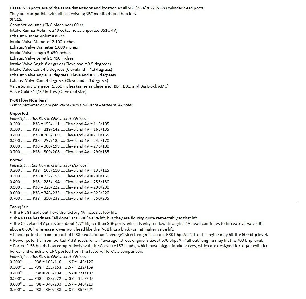
Since we're considering Dart blocks with SBF architecture, there are many in-line valve cylinder head choices too (SBF port dimensions); such as Edelbrock, Trick Flow, Air Flow Research (AFR), Roush, and Ford Racing's bitchen N351 sportsman heads. Another unique choice in cylinder heads is the Kaase P-38 heads. These heads have SBF architecture, they are direct bolt-on heads for a SBF/Windsor block, they use SBF/Windsor manifolds and headers, yet they have canted valves! Jon Kaase was a protégé of Dyno Don Nicholson, and he is a devotee of the Cleveland cylinder heads. Kaase's P-38 heads are hybrid SBF/canted valve heads, they have well designed modern combustion chambers, and they flow better than Cleveland heads especially at low lift.
Sonic Choke (Limiting Port Velocity)
Gas flow in an intake port is hampered by sonic pulse reversion when the gas velocity reaches approximately 55% the speed of sound; this gas velocity is known as the “Limiting Port Velocity”, and the property is referred to as sonic choke. “Limiting port velocity” is not based on the port’s average velocity, rather the port’s peak velocity at the induction system’s point of “minimum cross sectional area” which I abbreviate as MCSA. The speed of sound is dependent upon the density of the air which varies from one induction system to another due to pressure and temperature. Sonic choke is anticipated to occur at approximately 660 FPS gas velocity within an “average” high performance induction system (based on 1200 FPS speed of sound).
This information is used to determine the MCSA needed to avoid sonic choke based upon an engine’s bore and stroke and its maximum rpm (red-line). Induction system designers “size” an induction system to complement the intended power band and displacement of an engine. Ensuring the induction system is large enough to avoid sonic choke within the power band is one of their concerns. For instance, based on the chart below a 383 cubic inch engine with a 6500 rpm red-line must have a MCSA of 2.3 square inches (or more) to avoid sonic choke from occurring within its power band. AND since 2.3 square inches is the MINIMUM cross sectional area, the AVERAGE cross sectional area of the induction system must be greater than 2.3 square inches.
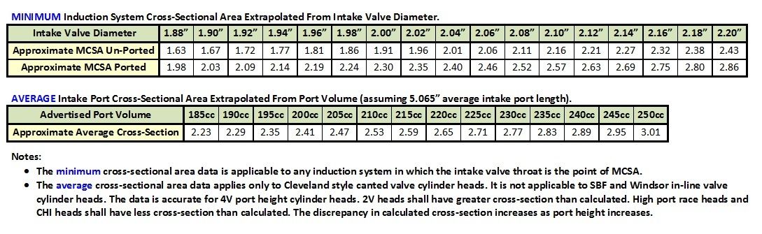
An induction system’s point of MCSA can typically be found where the intake port passes between the push rods of most overhead valve (push rod) engines. This is not true of Cleveland style canted-valve cylinder heads however. The canted-valve geometry spreads the push-rods apart where the intake port passes between them. With canted-valve cylinder heads the point of MCSA is normally the valve throat, located within the valve pocket just above the valve seat, which by the way is the proper place for the MCSA to be located .
Points to learn are (1) too much port velocity actually inhibits horsepower, (2) ports can be too small just as well as they can be too large, and (3) ports which are sized too small, with the intention of increasing gas velocity, end-up behaving as high rpm restrictions.
The numbers in the chart are approximations, using an abbreviated calculation method. But they are quite satisfactory for predicting induction system performance.
Now that you’ve determined the MCSA for your application based on “limiting port velocity” you can use the charts below to determine if a particular cylinder head meets the requirement of your application. Unfortunately cylinder head manufacturers never publish the intake port’s average cross sectional area or minimum cross sectional area. The information below is not “measured” data, it is extrapolated from intake valve diameter and port volume to provide “approximate” data for average and minimum cross sectional area.
Proposed Custom Engine Project - 550 Horsepower
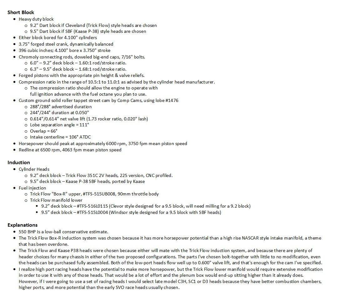
Kaase P-38 Heads & Trick Flow 351C Heads - here's additional information:
Kaase P-38 Video
Trick Flow 351C 2V Video
My post has run-up against the software limits for post length. I can't add anything more.
If anything needs clarification or elaboration .... lets discuss it!