Next I'll get on with cleaning up the engine bay. The gas tank has to come out. Mine was easy, as it was not being held in (!!!!):

There has been an odd creaking noise coming from behind me, ever since I've had the car. Whenever going over sharp bumps such as a railroad track. Now I think I see why:

I'm not going to be a real stickler for originality, so I want the clean bay look. I used an air chisel to remove the metal straps for the A/C lines and electrical bundle. This proved to not be so wise. It tore away the base metal, and left me with holes to fix:

Here the hole has been rounded and I am preparing to weld in a small plug. Using magnets to hold it in place. Magnets really mess with the welder's arc, so use another method if possible. That super sticky aluminum tape used on A/C ducts works pretty well.

I've used an air powered scraper tool, and in some places ordinary paint scrapers, to get most of the "tar" off. Heating it helps to soften it, using a heat gun or propane torch. Use care; the stuff will burn if you get it hot enough.


Following that with rags or paper towels soaked with mineral spirits yields a clean (?) metal surface.


If you have high humidity like I do, wipe the bare metal down with ospho (a phosphoric acid solution) to slow down surface rust.
Here I am going to remove this grounding stud, which I don't use. Shortly after I bought the car, I moved the battery to just in front of the right rear tire, and ground directly to the engine block. Of course, if you are staying all original, you would not do this.

This tear is on the left side, at the emergency brake cable opening. Possibly damage from a stub axle failure, as the axle opening was a little beat up too. Pics that follow show the repair process, which was pretty easy in this case:


Here is a little tip I learned; if you can reach both sides of a repair, and one is more visible than the other, weld on the less visible side. It will save you time on post weld grinding and finishing.
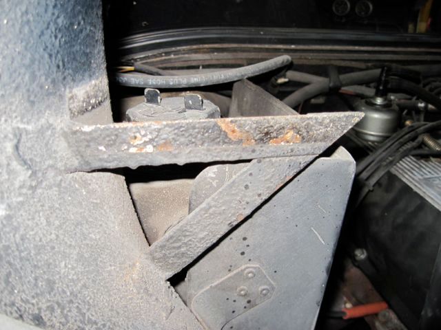
OK, another departure from originality. I have stabbed myself for the last &%^*$*! time on these things:

I actually cut off a couple of chunks of rubber hose and shoved them on to these brackets to keep from really hurting myself. If you intend to keep them, I suggest you do the same while you work in the engine bay.
Going for the clean bay look, I decided to make new brackets not only for my safety, but because they were ugly. The factory welder had blown a hole through the sheet metal at one of the welds; never fixed it. Been there 44 years as far as I can tell.


Here is my design for the new bracket, with the cardboard template I used to shape it:

Removing the original brackets left patches of rusty metal and some holes, which had to be fixed:


Before removing the old brackets, I measured their positions, and made a simple wood brace to reach from left to right. Here I am using it to hold the new brackets in place with clamps. This way, the new brackets support the engine cover panels in the same positions as before.

A test fit of the covers:

Next I'll scuff up the metal, and grind off any burrs and other obvious defects.


Give it a good cleaning, and apply the first coat of epoxy primer with a brush. It doesn't look so great, but most of it gets sanded off anyway.


Here was a factory boo - boo. The inner and outer panels did not completely overlay, and there was a funny looking gap here. Cosmetic mostly, but easy to fix with a small piece of metal welded in:

Finally about to wrap this part up. The inside of the engine bay is really wavy; it will take a lot of work to smooth it out. Right now I am just going to address the gross issues. This is not the end of my work here, just reached a point where I can leave it and move on.


This coat was sprayed: