ZF RefurbishmentGiven that I had some "downtime" on the car due to an engine build, I decided to address a second gear "crunch" that I had in my ZF. If you check out this thread, it describes a previous project to safety wire the ring gear bolts...
Thread: "Am I the Luckiest Guy in the World? My 2nd gear synchro situation had been basically the same since I purchased the car, and the previous owner had lived with it. It was manageable by performing a very slow and deliberate shift from first to second.
It seemed to be getting a little worse, so it made sense to try and address the problem, since my transaxle was just sitting on the garage floor during the engine rebuild.
Finally, late in the ZF reassembly, I had the opportunity to obtain a "taller" (.642 ratio) 5th gear to replace my stock .704 ratio gear. The benefit of this is to drop engine RPM by about 4-500 RPM at 80mph, and give me bragging rights for a ~165 mph capability at "stock" redline. I am not sure I will try to achieve 165+ anytime soon, but it's nice to know it's there in case I need it.
So without further ado - I wanted to discuss what's inside a ZF case, and what specifically I did to my box. This discussion leaves A LOT of the specific steps out. Ensure that you have your ZF manual, and follow steps EXACTLY, or you may break something! This transmission is like a Jigsaw Puzzle, and it only goes back together one way.
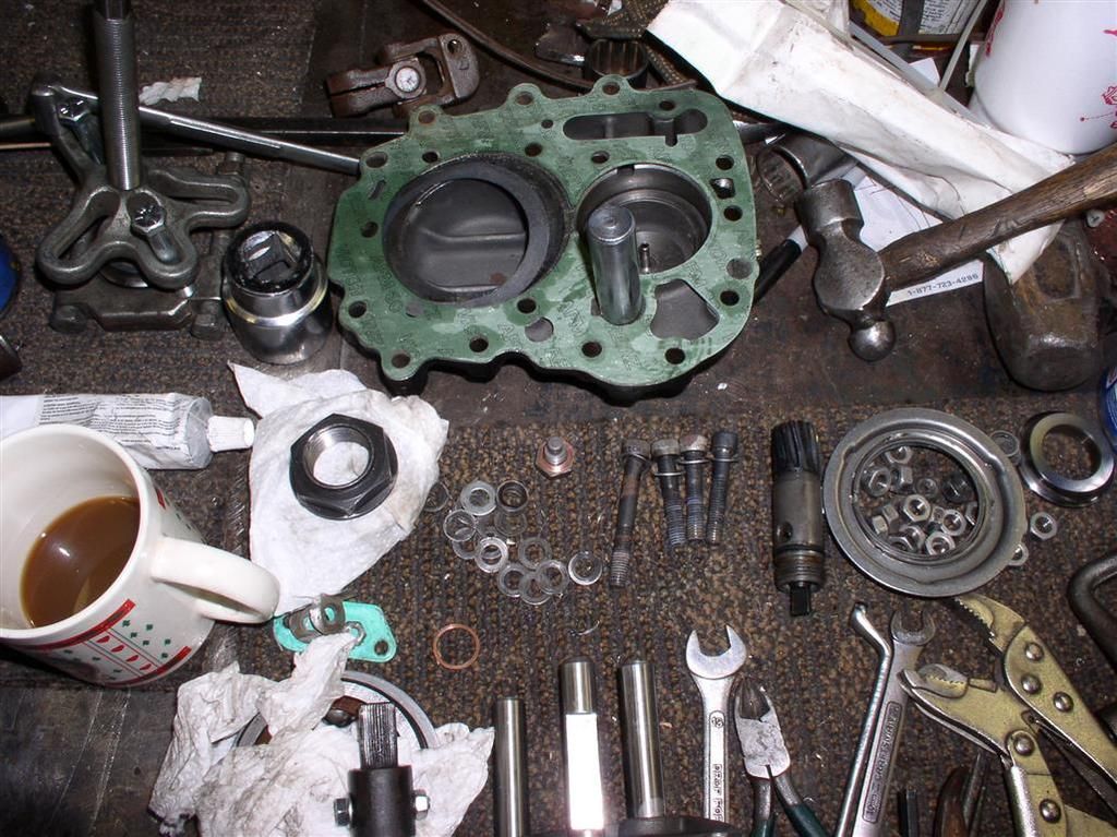
I won't go into much detail here on the "basics" - draining the fluid, removal of all the "accoutrements" (Speedo Drive, speedo gear, etc.). Make sure the box is in neutral when you start. Remember - it's a lot more pleasant to work on a ZF if the case is clean.
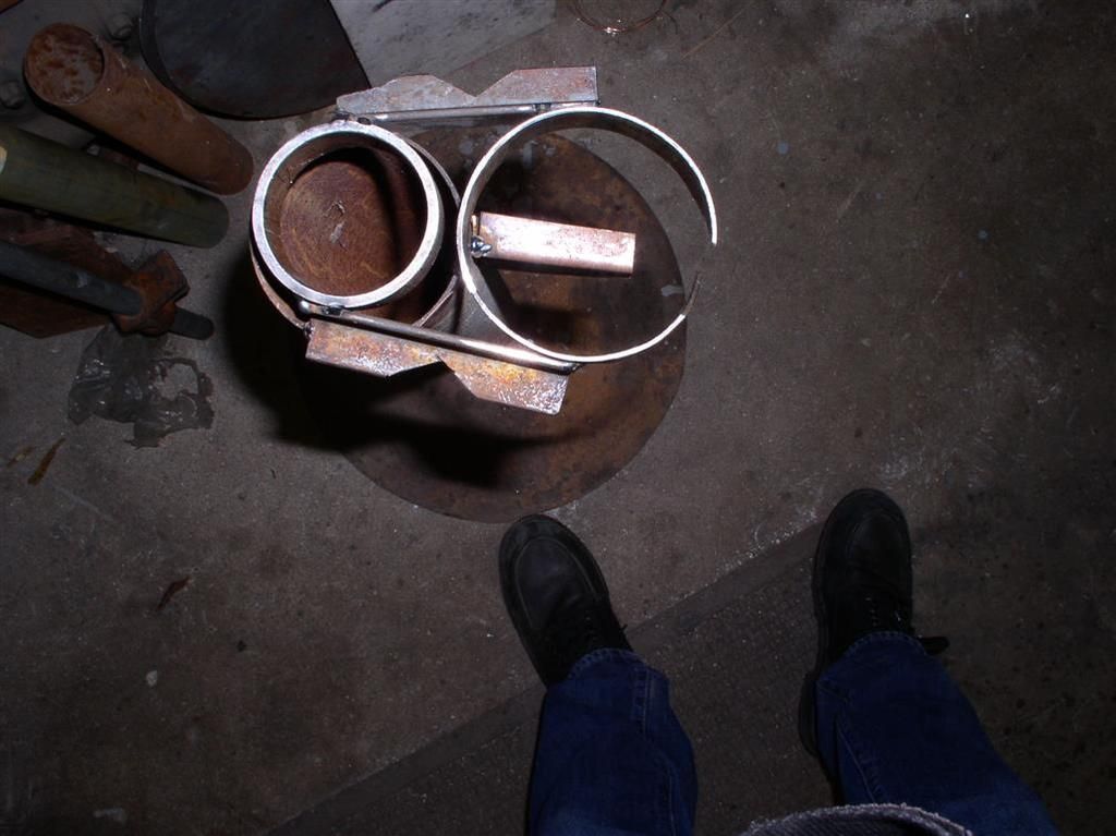
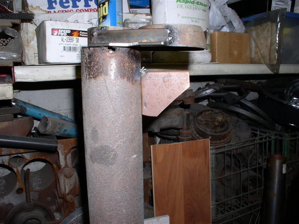
So the first thing is to build a fixture: The dimensions are 52mm and 79 mm (with an 80 mm center to center distance). On the fixture, you need to have reliefs for the shifter shafts, and the fixture needs to be able to handle the roughly two foot long input shaft that is always poking around in your way. On the W-Wade-Co fixture, we ended up putting a positive stop on the large hole to keep the roller bearing from slipping through.
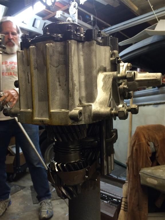
 Given that the case can be split without removal of the ring gear, I don't plan to cover this in detail.... Although we did it on mine. But here is pictures of what it looks like inside the housing....
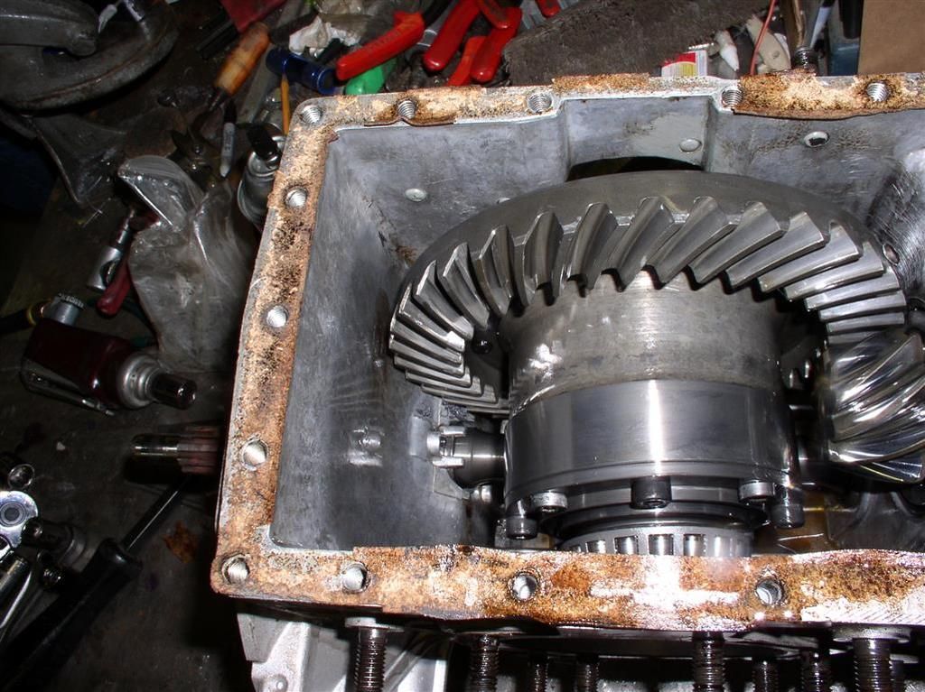
I might augment this section later, if there is demand.
Just watch those shims on the long lover cover bolts and put the bolts, shims, washers and cover back in the EXACT SAME orientation as you removed it!
Open the Shifter Box Cover Remove the shifter cover, and look inside. Remove the two "grub screws" holding the shift rod onto the shift actuation ring. We took this apart so we could clean it up, and put fresh grease in it.
You really don't have to remove the cross shaft from the case - we didn't. There's some kind of wacky mechanism under the little pointy cover on the passenger side. It's easiest to leave it be.
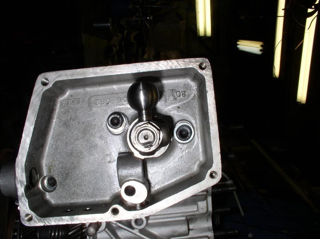 Remove Cast Iron Cover
 There are two bolt holes in the cover that you can thread 8 mm x 1.25 pitch bolts through. These bolts push on the aluminum case to back the cover off. Here's what the cover looks like when it's off the back of the case.
The big steel shaft holds the reverse idler gear on the inside of the aluminum case.
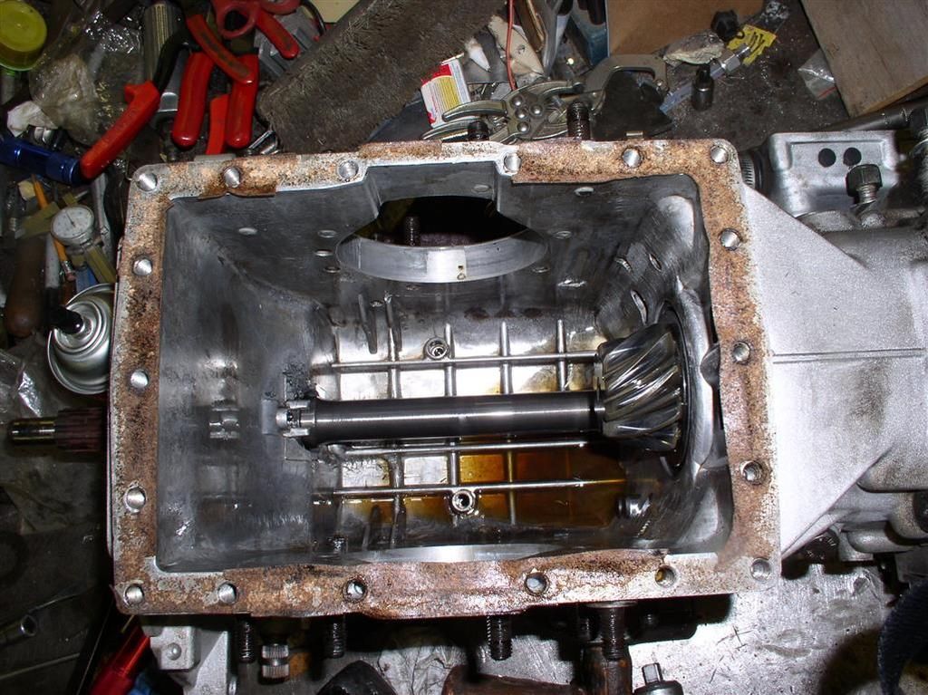
Here's what the back of the aluminum case looks like with the nuts still installed.
Note that there are a bunch of shims between the rear bearing races and the cast iron cover / case. In the case of the output shaft (the big one), they set the pinion depth.
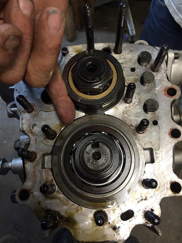
Unstake the nuts on the input & output shafts and remove the nuts and bearing races.
Remove Reverse Detent and Spring.
Split the Gear Case Carefully split the case, and slowly back the two gear sets out of the forward portion of the ZF case. You may need to turn the two side output flanges a little to get the pinion off of the ring gear.
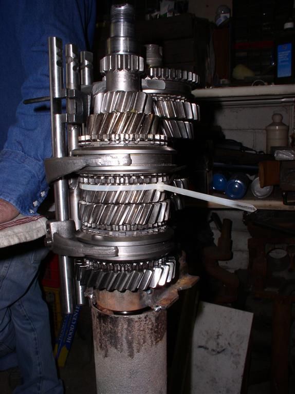
Move the whole gear stack, which will still be installed in the rear half of the case, and mount it in your cool ZF holding fixture.
Remove the "grub screws"" on two of the three shifter shafts. One pair of screws is accessible with the case split, the other pair is under the little access panel on the passenger side of the box.
Slide the shift rods out of the case (down).
Work the two gear stacks, and the single shift rod and collar down (actually, raise the rear case up off the gear stacks). Once the case is off, the gear stacks are free. Remove the shift collar and the shaft.
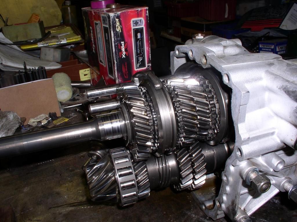
Here's what the gear stacks look like our of the case. The top is the input shaft, the bottom is the output shaft. The little gear is your reverse idler.
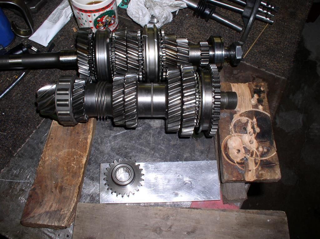 Output Shaft - The one with the Pinion
 The output shaft has Reverse / First on it, it's at the end opposite the pinion.
If you are not changing a gear, then you may be able to leave this alone. When I took mine apart, I found a whole lot of "spooge" under the gears. You can also clean up the 1st/reverse shift collar on this shaft if you are in there, but.....
I am not going to write a lot about this, unless by popular demand.
Note that if you are going to a "taller" 5th gear, you have to disassemble this shaft, and also mill one of the shifter rods to clearance the gear.
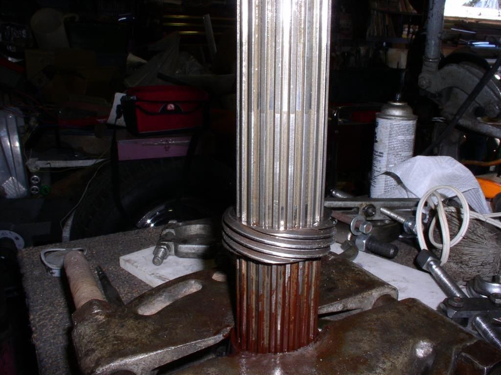
Input Shaft - The one with the Long Snout This one comes apart if you are working on synchros. You need a press. You need to follow the book. You need to be careful. You need to know some tricks. But it's not black magic.
But after you split your case, and before you do anything that I have described to this point, measure your Synchro Clearances. I measured:
1st .050" Great! First Gear synchro never wears
2nd .000" Terrible! This was a worn cone, not the syncro ring!
3rd .036" Good - Pretty Nominal for a 100K Mile ZF!
4th .033" Good - Pretty Nominal for a 100K Mile ZF!
5th .033" Good - Pretty Nominal for a 100K Mile ZF!
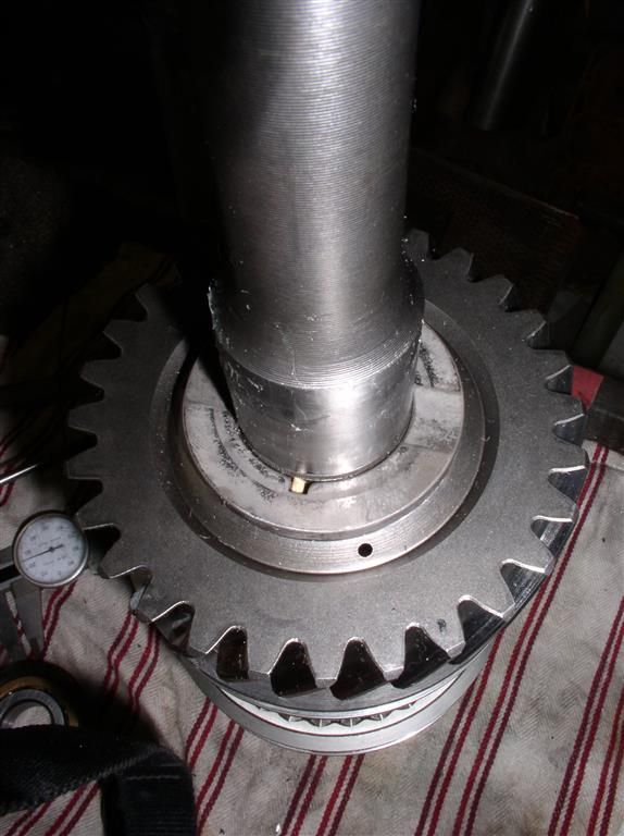
Here's more pictures of the input shaft. Especially note that little pin. It's wise to remove it before you press any gears off the input shaft (in this picture it's a little wooden dowel used as a length guage).
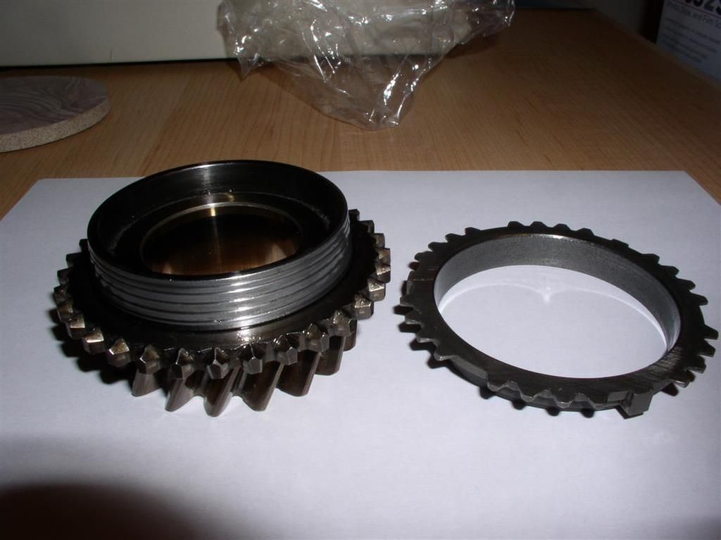
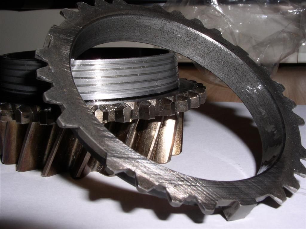
 Second Gear Synchro Repair
 The precise measurement data I collected on the indicated to me that the wear was primarily on the cone, and not the syncro ring. This was confirmed when I used the 1st gear synchro ring on the second gear cone. I got the same clearance (0.000"), but the first gear synchro ring is never worn, because it doesn't have to do any synchronization like second gear does. Therefore... this confirms issue is with the cone.
Insert CRM Write-Up after successful test.
Anyway - here's my repaired 2nd gear and synchro.
 5th Gear Upgrade
I also hooked up with one of our members, and got a "taller" 5th gear (was .704, is .642). This is a pretty simple install on the output shaft, but it also requires the milling of one of the shifter rods (due to the expanded diameter of the 5th gear).
Here is the milled rod. I got precise dimensions by calling Lloyd at RBT.
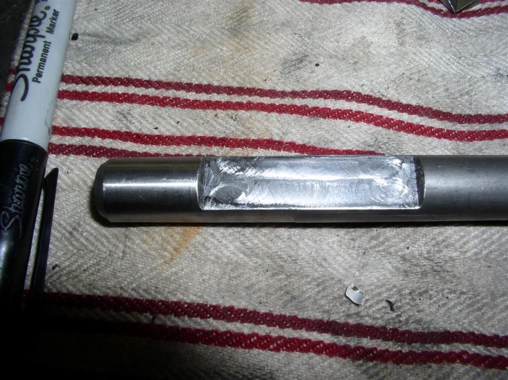
Here is the milled rod, installed before the cases were assembled. You can see the 4th/5th shift collar on the right, and the milled slot to clearance the larger 5th gear.
Reassembly - Just Do Everything Backwards! You need or know some tricks. You need to be careful. You need to put everything back in the right order. You need gaskets, and sealer (I used the equivalent of Yamabond FPIG sealer). You need to torque everything carefully.
The very first primary testing of the gears should occur before you insert them into the front of the case. Verify they all spin freely, and that you can use the shifter to move all the shift collars around. Don't do it like I did, and test the function AFTER you reassemble the two case halves.
The issue that I had was the gear actuator tab on the cross shaft didn't get aligned properly (and seemed to lock the first gear up). So when the shifter was in neutral, the gear stack was in first, and when shifting to any other gear, the ZF was locked up.
Correction of this minor issue took another 3-4 hours to resplit the case, clean up the mess, install a new gasket, and re-reassemble things.


_(Medium)")

")
_(Medium)")