Hi Rocky,
Just getting caught up on some of the updates... First...I think 45min drivetrain removal may be a record. Wink Very impressive. I think the Alt/AC bracket is slick.
- Sorry to hear about the rod bearing. I share your concern...why did it happen. I never like just moving forward w/o fully understanding the failure. Seems every time it do, I ended up with the failure again...
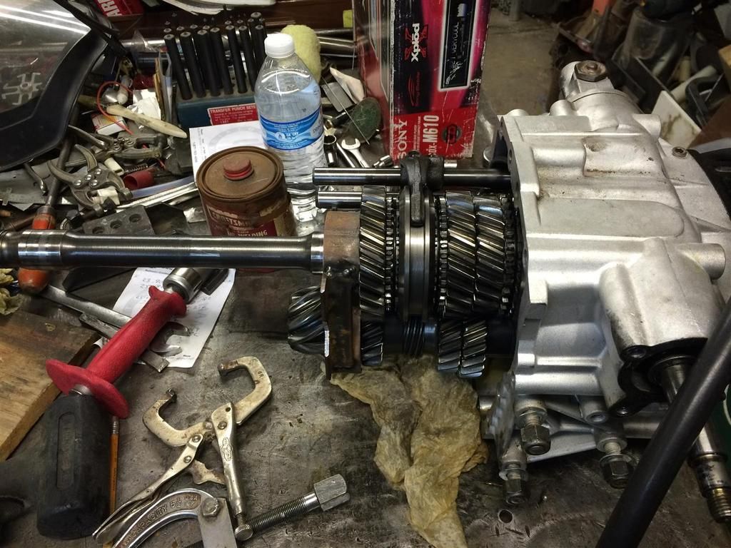
- Would love to see some detailed pics of the trans fixture when you get a chance.
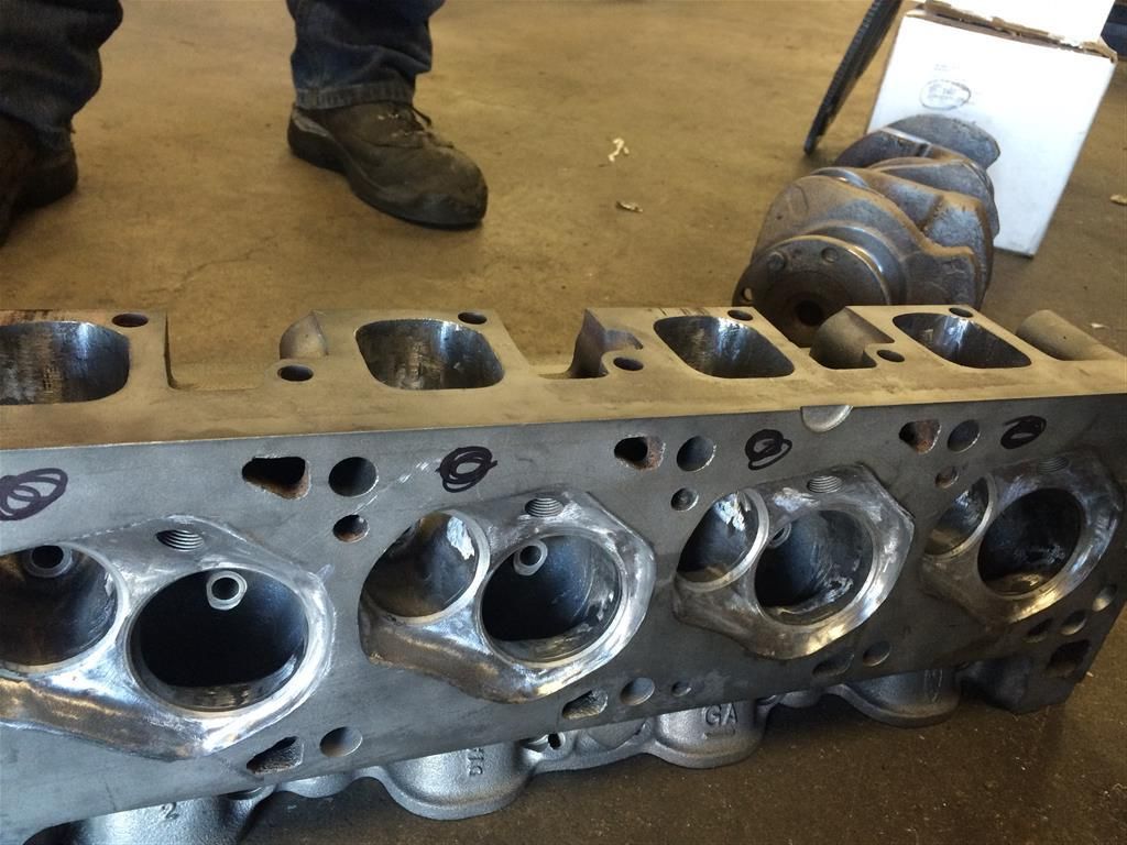
- On the heads, what did you mean by "minor hole drilling for water flow"? I have never done this on the 351C heads, and would like to understand it more.

Keep us posted. Thumbs Up!
Thanks for the compliments!

My 45 minute removal didn't include all the work leading up to it - I'm not really THAT fast!


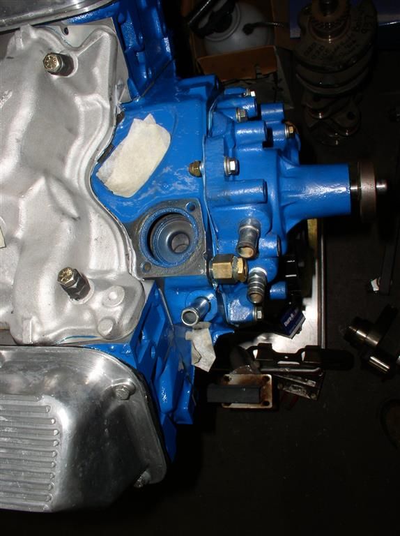
With regard to "Block and head drillage" - my block has an additional set of holes that match a set of holes in the head gaskets. The holes planned to be added to the heads are "loosely" located where the sharpie circles are.

The machining will certainly be more precise than the circles shown.

Benefits are more cooling of the exhaust port area.


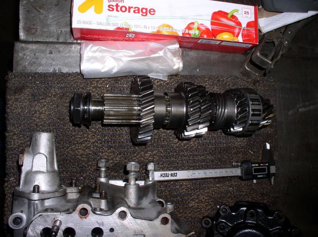
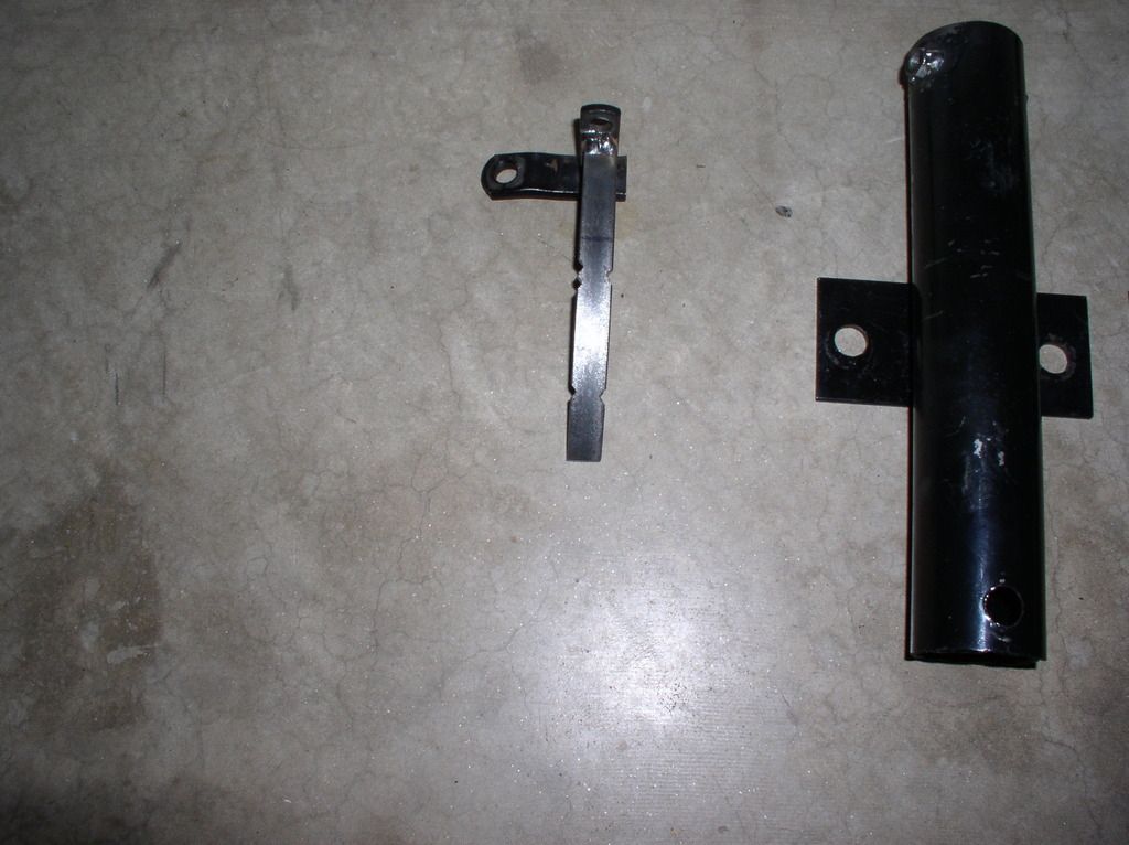
Here is the ZF Fixture mentioned in a previous post, and some shots of the assembly on the stand....

This fixture was welded to a vertical tube (you can see the base of the stand to the far left of the picture - to the left of my shoe). It gives very good access to get the "stack" out of the case...


Fit Check:


Viola!

I figured it was time to put some more information up....

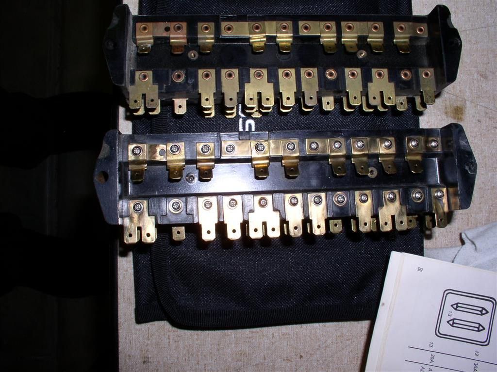
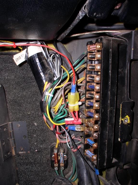
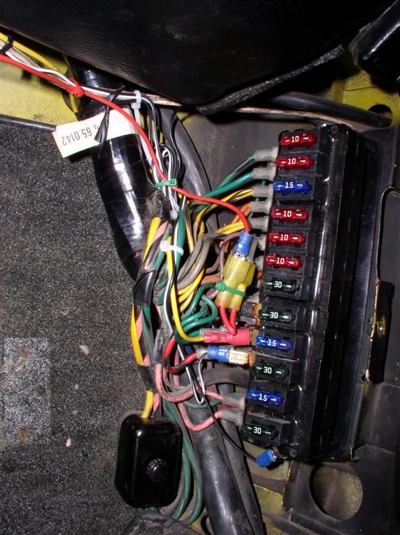
Latest project: Pantera Parts Connection ATO Fuse Box install.

Went in pretty easy - just a little pain-staking.

I always wanted to go to this type fuse although I never had any fuse problems... (knock on wood).

Took me about 1 1/2 hour for the install.

The old and the new - note how the PPC fuse box (lower) is interconnected with screws, vs. the old box, which uses a copper rivet technique.


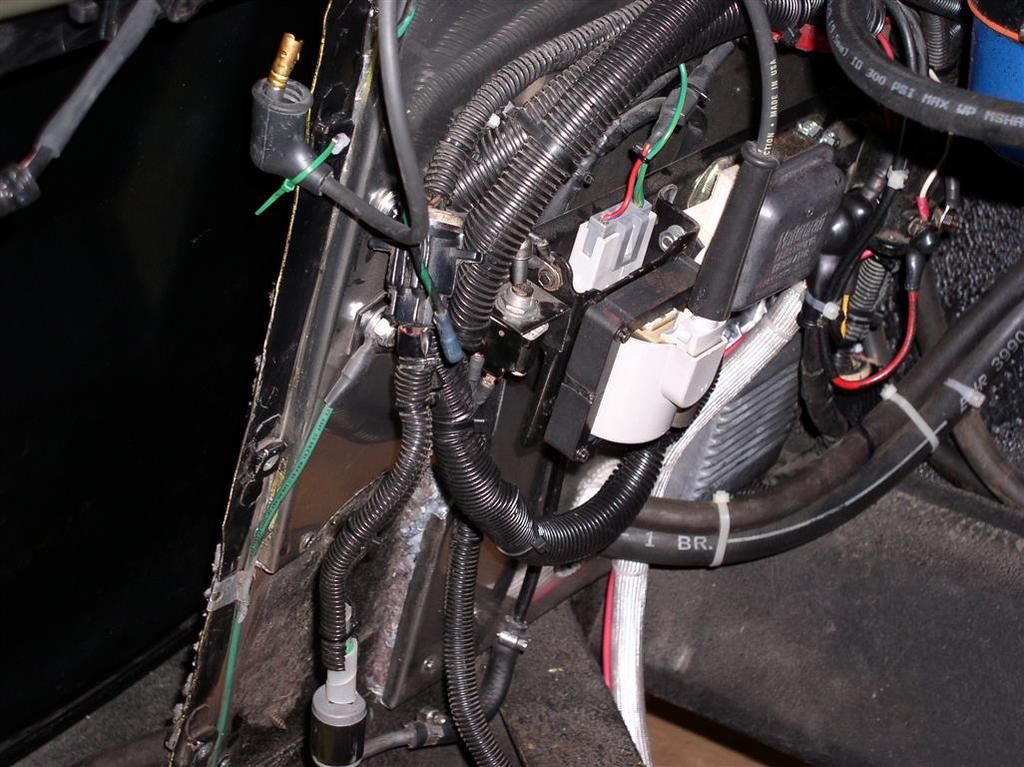
My old wiring - here's what it looked like in there....


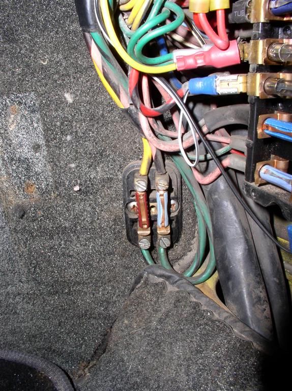
Window Fuses - Don't have an ATO box for this, but I do have a cover!....


Viola! - Finished result. Still need to swap out the fuzes to the representative values, but since my ZF & engine are still a little ways out, I have a little time.

So if you are watching this thread, you might assume that I am not doing much on my car....

Well, you might be right, but I have not been COMPLETELY idle....

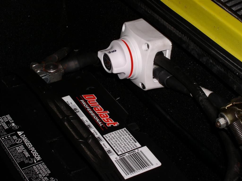
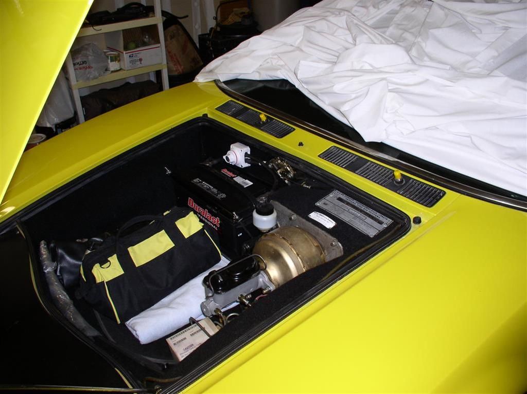
Here is the new battery disconnect switch, based on a realtime observation of a Pantera that had a starter that locked in the ON position...


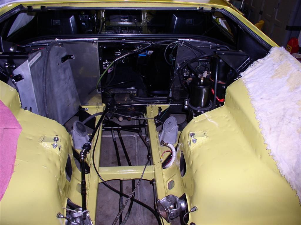
Here's the "cleaned" engine bay...

(unfortunately, it doesn't look that much different than last time....)


Better organized than last time.....


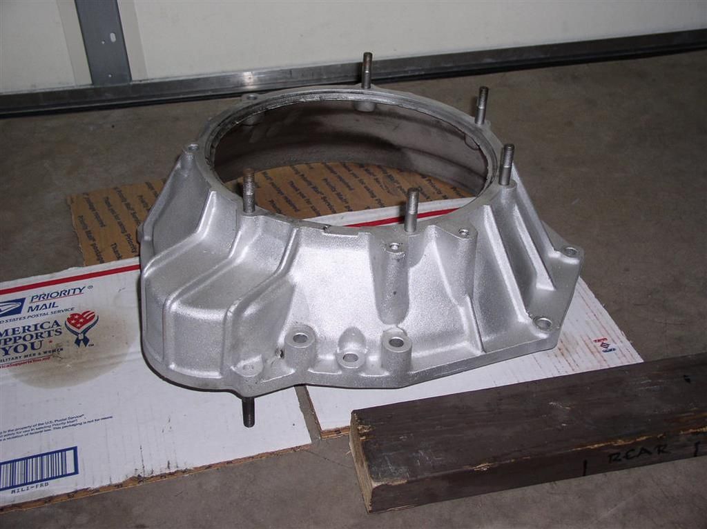
Nice looking bell housing, I would say...


My motor is closer to reality... (2-3 weeks out). Working on rounding up the parts for the ZF - that's the big one now....

Rocky
Last edited by rocky
Completed my Taurus Motor install. Thanks to Dale Gumm (longtime POCA member & DeTomaso owner) for the parts, and the instructions.

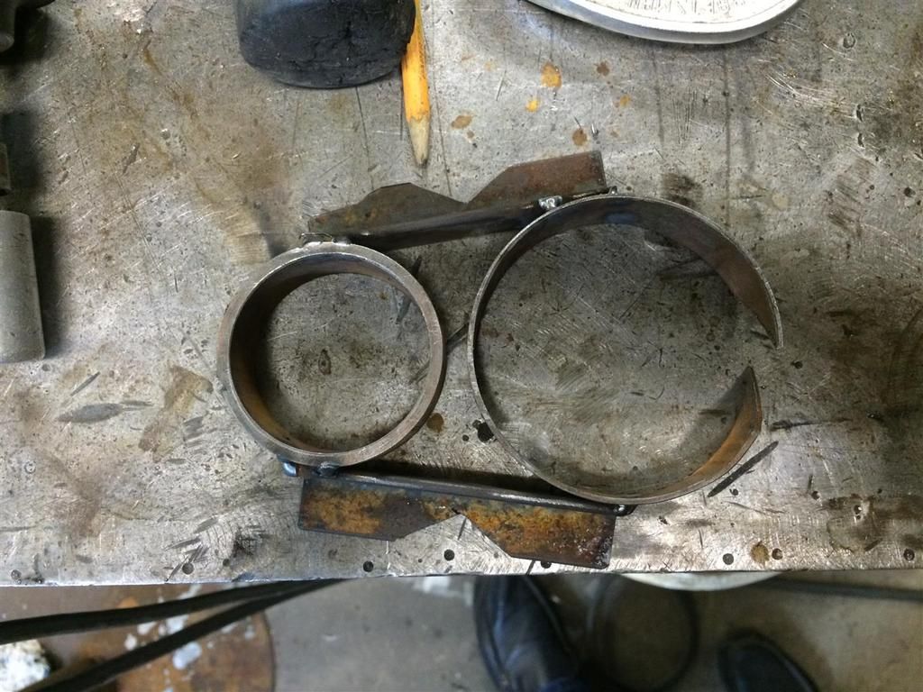
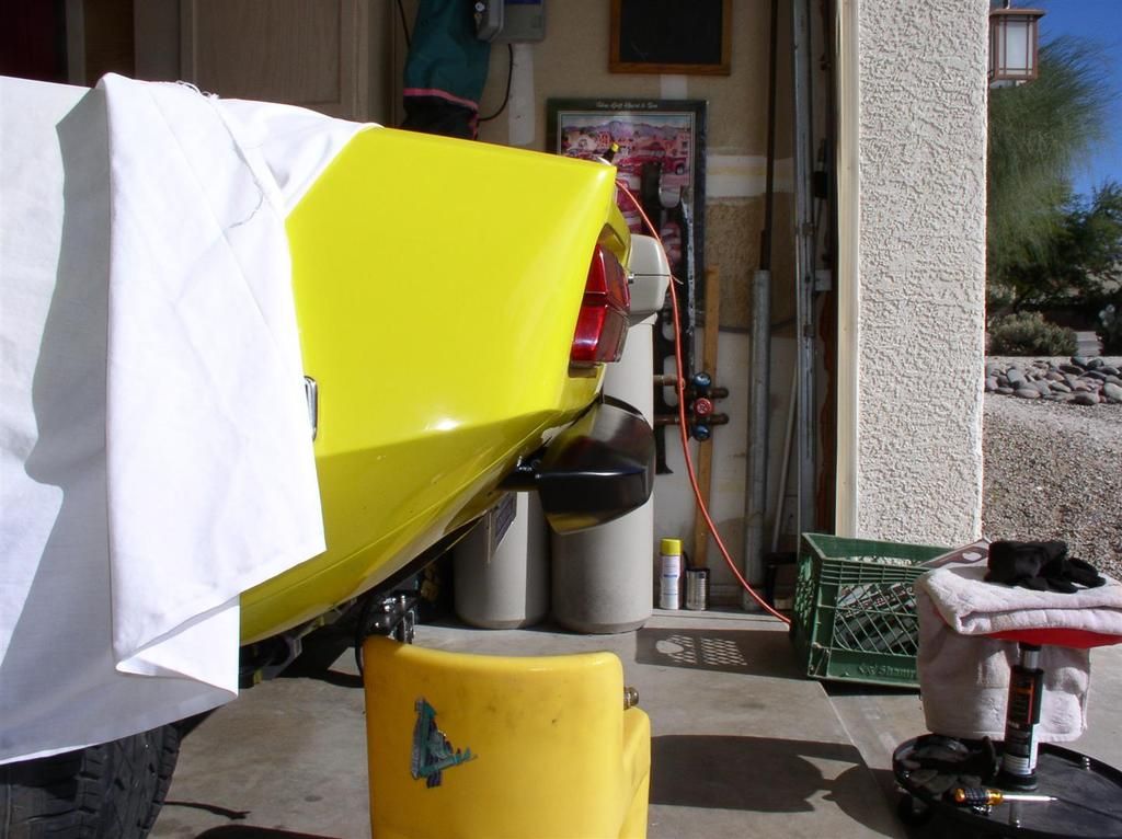
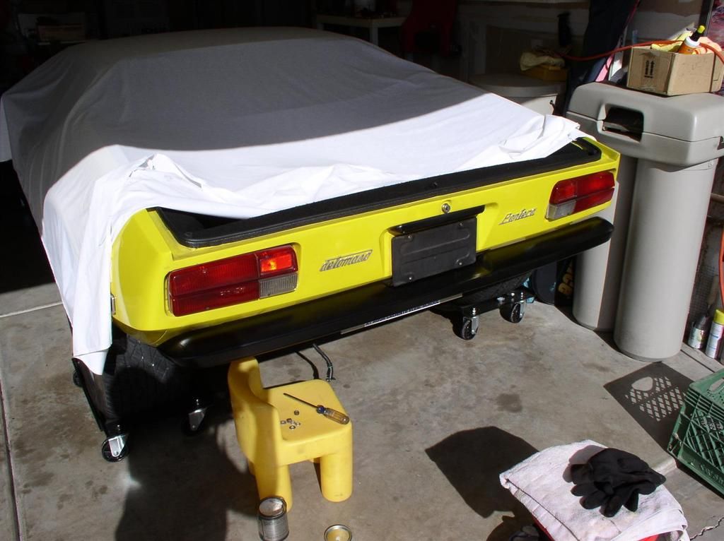
Also have my "reduced clearance rear bumper mounts" welded up. These will bring my L-model rear bumper back much closer to the car body - I think it looks better that way.

It also reduced the vehicle weight by about 2-3 lbs.

I think that no one will hit me in the back end.....

The end tubes are only temporarily installed. I need to drill the smallest diameter pipe to mount the bumper bracket, slide them to the correct depth and orientation, and then weld them up and paint them....

Bumpers and engine screens are going to be powder coated.

Rocky

Attachments

Images (1)
  • P1010011_(Medium)
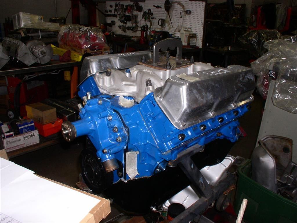
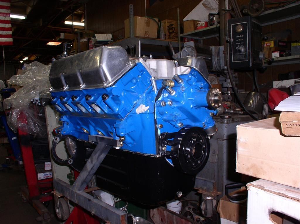
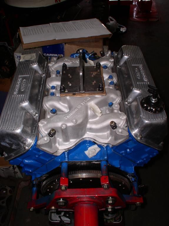
Big News - Motor is Done! Whoo-Hoo!

So my motor has been through the wringer (actually, the washer), and it's now complete and ready.

Now I have to finish my transaxle.

Basically the engine is the same as it was except....

Reduced Compression from 10.5:1 to 10:1 via:
  • D1AE GA Closed Chamber Heads
  • L2379F .030 Flat Top Pistons
  • Judicious Milling of Deck and Heads

    Slight "Align Bore" (.005") to ensure Block and Crank Alignment
  • Main Bearing Clearances Set (.0025")

    "New to Me" Crank (351C Cast - Nodular Iron)
  • Checked for Straightness
  • Micro Polished
  • Rod Bearing Clearances Set (.0025")

    Intake Manifold Heat Riser Block Off Plate

    Flow Measurements Collected with:
  • Intake - Heads Alone
  • Intake - Heads and Intake manifold
  • Intake - Heads, Port Plates and Intake manifold
  • Exhaust - Heads Alone
  • Exhaust - Heads and Headers


  • Last edited by rocky
    Engine is beginning reassembly.

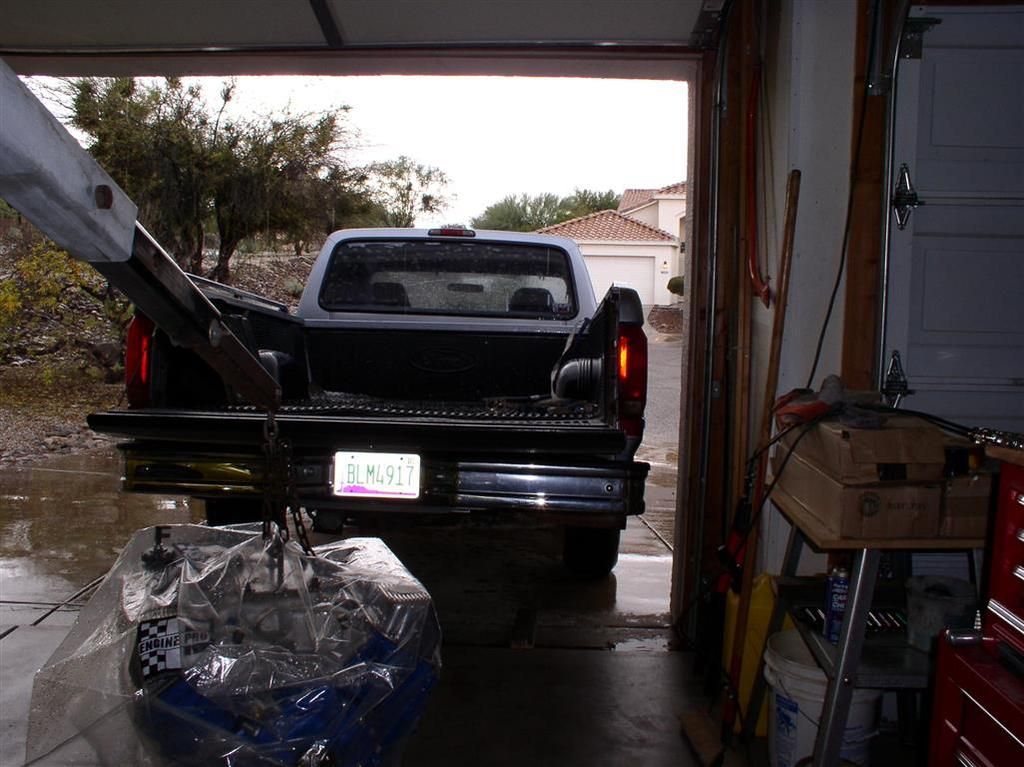
    WHENEVER I take this engine out from undercover - it rains. It is unbelievable. Saturday morning we got hail.... In Tucson AZ!


    So I first did some of the real basic stuff - got the flywheel on, intake manifold bolts, oil pressure sender, PCV plumbing, etc.

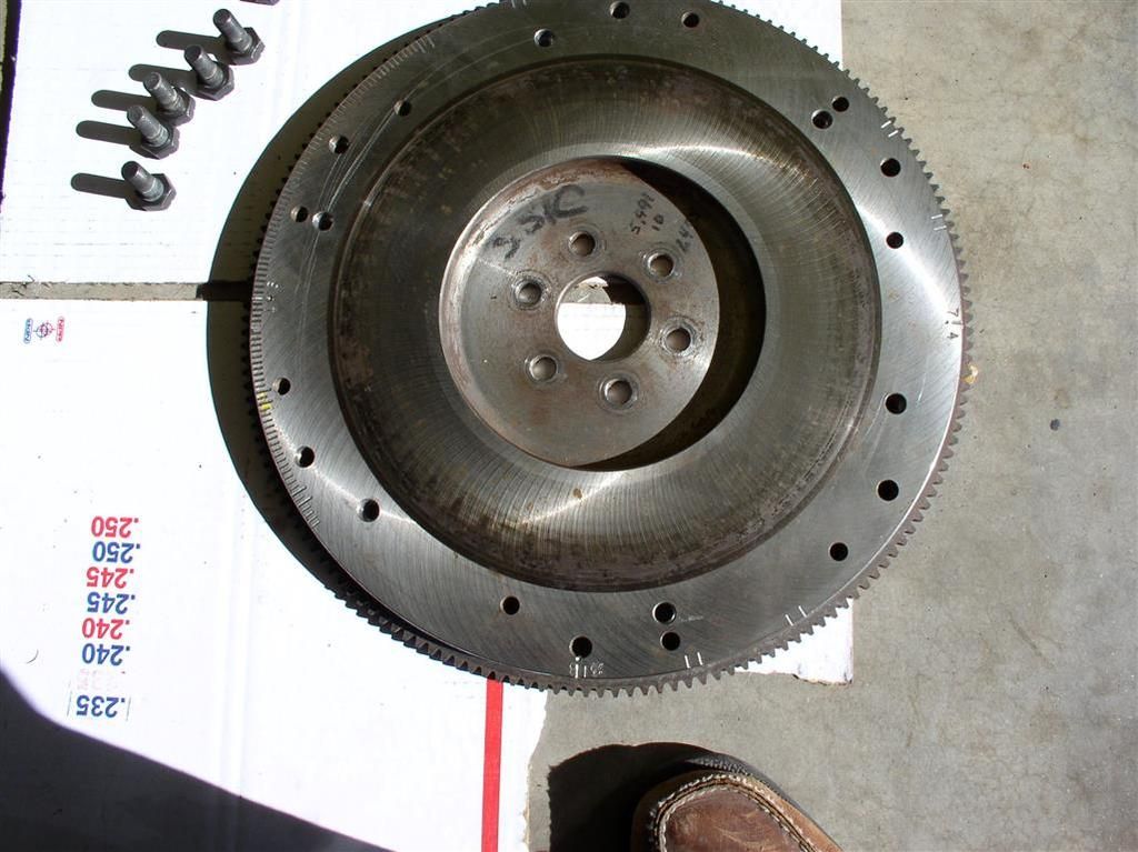
    Did you see this cool flywheel? Now it's degreed on every cylinder pair at 0 Deg, 16 Deg and 36 Deg.


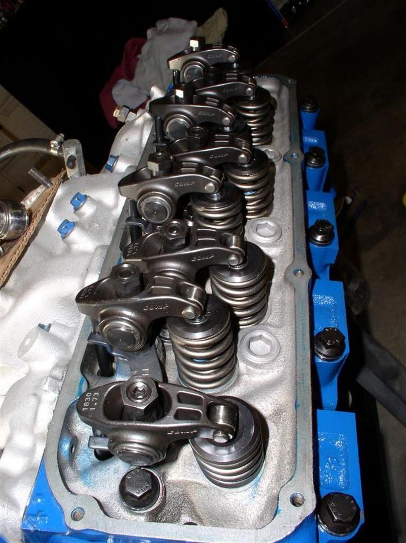
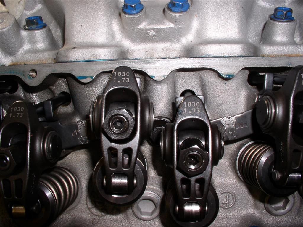
    Couldn't help pulling off the valve covers to see that beautiful rocker assembly...


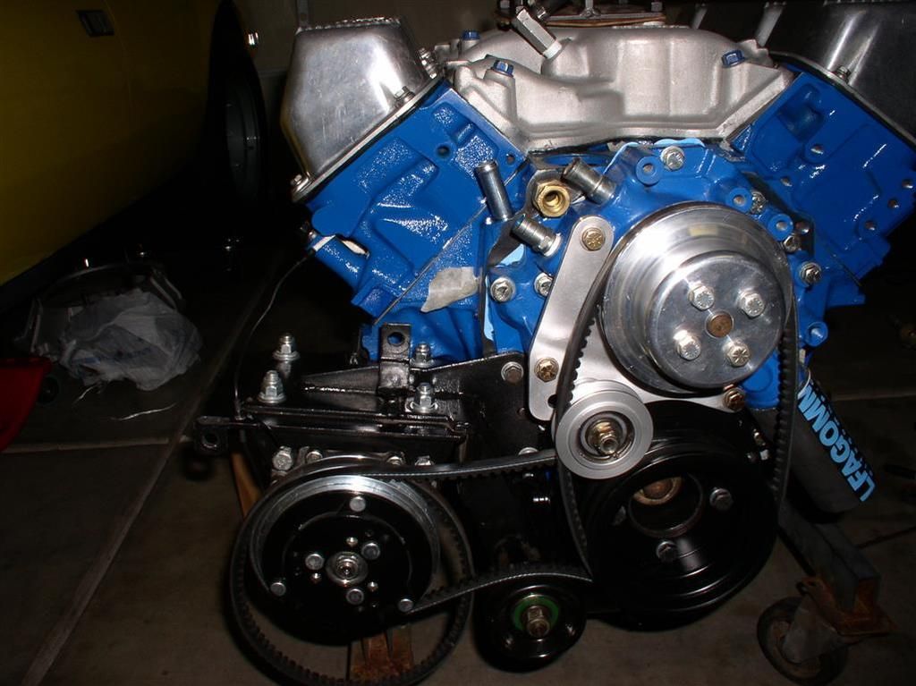
    Today I got my AC Compressor and outboard alternator, and all the belts/pulleys attached.


    Also received the remaining ZF parts from RBT. Assembly begins soon.

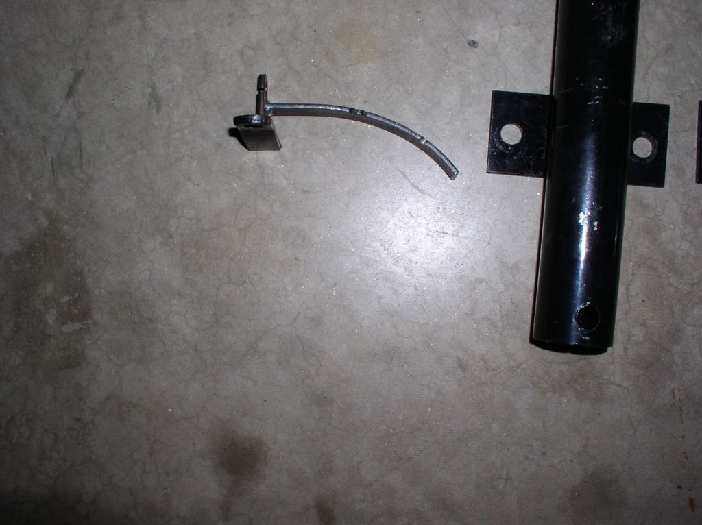
    Finally - I am excited about my new Throttle Cable support bracket (John Taphorn design). I am sure this will ALWAYS give me a "full pull" on that throttle cable....


    Finally - coming back together!
    Chuck,


    Looking great! Two words of advise... If you are using Kirk's engine cover , make sure that your water pump tentioner pulley clears . It sometimes takes some massaging to clear.
    Second, you might want to enlarge the three compressor mounting holes in the block. The front two bolts go from 5/16" to 3/8 " and the rear one goes from 3/8" to 5/8" . That is a LOT of weight hanging off of those small bolts!
    I once had a block crack along the boss that the rear bolt attaches to and leak coolant.
    Ron
    Still making (slow) progress. Standing by for a couple of parts of the ZF. In the mean time.....

    Got my engine screens back from the powdercoater.... They look super in a wrinkle finish black.


    Also got the bumper powdercoated in a satin black.

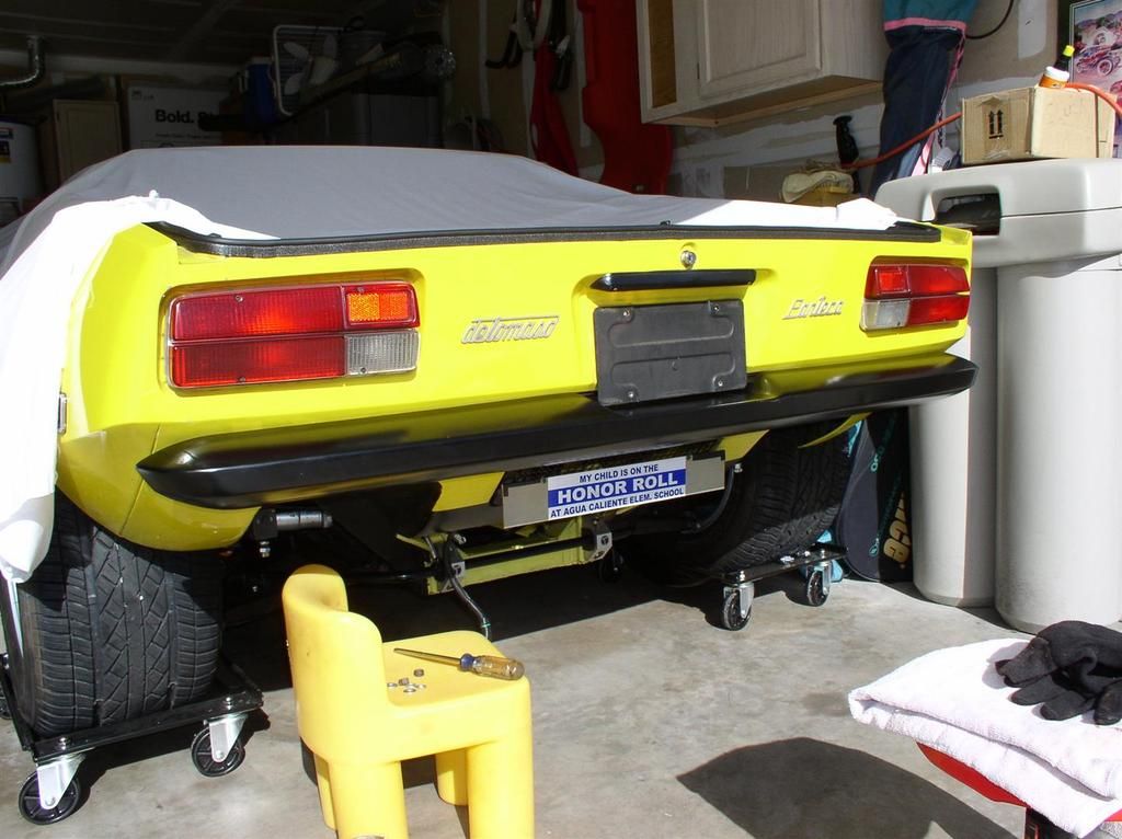
    Completed my "flush mount" rear bumper project. The intent was to move the bumper in about 3 inches closer to the body. It looks good, but honestly, for all the time I spent on this, I am not sure if the results are as noticeable as I thought they would be.

    Nevertheless, another project completed!


    Anyway - progress continues!

    Rocky
    quote:
    Originally posted by Rocky:....
    Completed my "flush mount" rear bumper project. The intent was to move the bumper in about 3 inches closer to the body. It looks good, but honestly, for all the time I spent on this, I am not sure if the results are as noticeable as I thought they would be...Rocky


    To me, it makes the CAR look finished, where the stand off looks like it needs to be pushed on some more.

    Something I just thought about and hope you addressed; with the standing off bumper, I remember the plates were slightly covered by the bumper. So does your plate now fit?

    Did the wire mesh for the engine cover get the wrinkle finish?
    quote:
    the plates were slightly covered by the bumper. So does your plate now fit?

    Did the wire mesh for the engine cover get the wrinkle finish?


    Moving the license plate up was just a matter of a little filing on the plate and frame to move it up about 1/4". The license plate frame sits on my bumper in the recess. I am going to have to go back in and put a little pad so I don't scratch up my new powder coating with the license plate frame.

    The wire mesh cover was done with the wrinkle finish. It came out great.

    Rocky
    Hey Larry -

    My buddy Wade (Mark IV/4280) has a mill with a rotary table on it.

    He basically uses the orientation of the bolt pattern on the flywheel to find the TDC point for the 1/6 cylinder pair on the flywheel.

    I am sure he has this reference orientation preset from working on many Ford motors.

    Update: He is less tricky than I thought. He just set the motor to TDC via the front balancer, and then marked out the window on the flywheel using the bellhousing. Once the limits of the window were defined, he just marked the degree marks so they would be inside the window.

    Once he sets his cylinder 1/6 TDC reference - everything else is based on this. It then becomes basically an engraving job.

    His rotary table is adjustable, and in my case, he just just marked off the 1 deg increments for the 1/6 cylinder pair. The 3/5, 7/4 and 2/8 didn't get the same level of detail, but just the key points.

    Update: The other cylinder pairs are marked at 0*, 14* & 16* and 34* & 36*.

    The intent is to allow a convenient reference for "quick checks" using any cylinder wire.

    The reference is set on the bellhousing by initially setting the timing at the front harmonic balancer & timing pointer (e.g. Cylinder 1 - 16 Deg. static advance at idle). The flywheel has a corresponding 16* reference mark milled into it.

    Once the static timing is dialed in (and verified) on the harmonic balancer in front, we just went to the little window in the back of the bell housing, and then use the 16* mark to set the reference into the bell housing. Basically we took a sharp file, and cut a line in the aluminum housing as our timing pointer.

    Having a mill with a rotary table is the key to this.

    Hope this explains the process.

    Rocky (a.k.a. Chuck)
    Last edited by rocky
    quote:
    Did you see this cool flywheel? Now it's degreed on every cylinder pair at 0 Deg, 16 Deg and 36 Deg.


    I like it Rocky and was thinking of doing something similar. I've frequently seen Panteras with flywheels marked at TDC or certain number of degrees advance for quick timing checks but that takes it a step further in convenience for running valve lash. In my case, I have a McLeod Street Twin and the pressure plate carrier covers the entire flywheel so markings would need to be on the PP carrier instead of the flywheel. I have a 14" Jomar degree wheel and was going to cut the center out it and mount it under the PP bolts but got a little squeamish about it at 7k rpm(one side is marked 180-180, otherwise the degree markings would be in the wrong direction for rear install). I think I'm just going to mark the PP with an etching pen instead. -Might be an alternative for anyone doing something similar on already assembled engines but you might need a degree wheel instead of harmonic balancer for desired accuracy. Accuracy is one very nice feature of the method Rocky shows in his post.....it's like having a built in 14" degree wheel permanently installed.

    quote:
    Basically we took a sharp file, and cut a line in the aluminum housing as our timing pointer.

    Another alternative is to drill and tap a small hole, and make a sheet metal pointer. It's adjustable to a degree and a new pointer with offset can be made if desired. This can also be done with the BH installed in the car.

    Keep the build pics coming Rocky.

    Best,
    Kelly

    Attachments

    Images (1)
    • Inspection_Window_Pointer
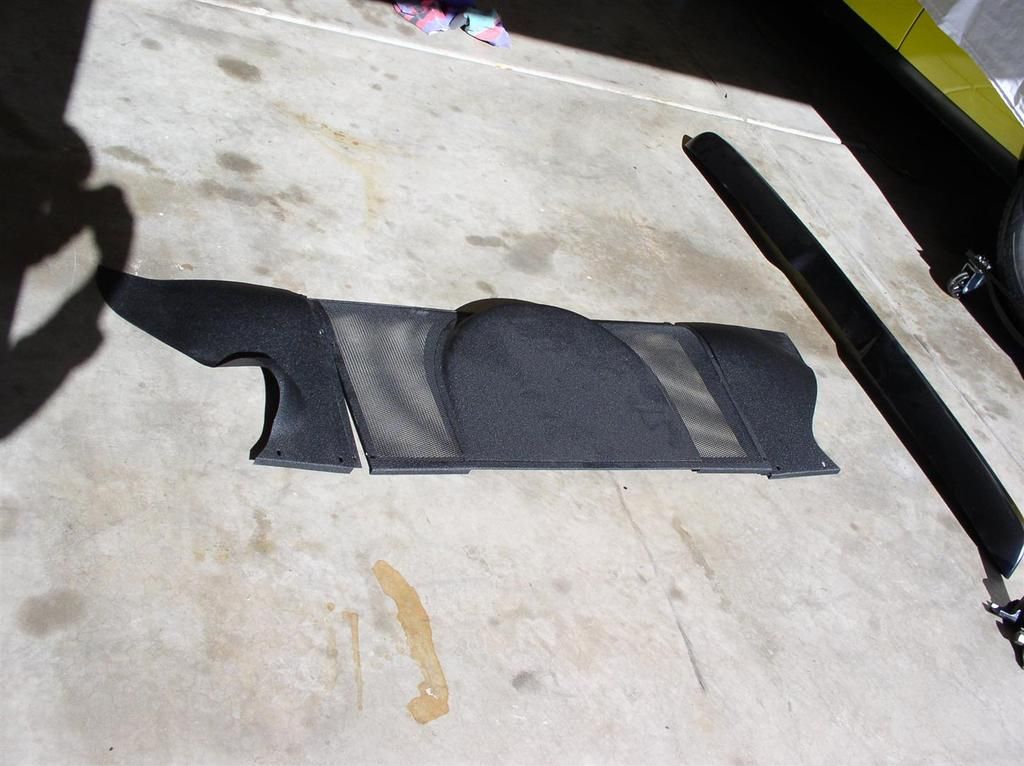
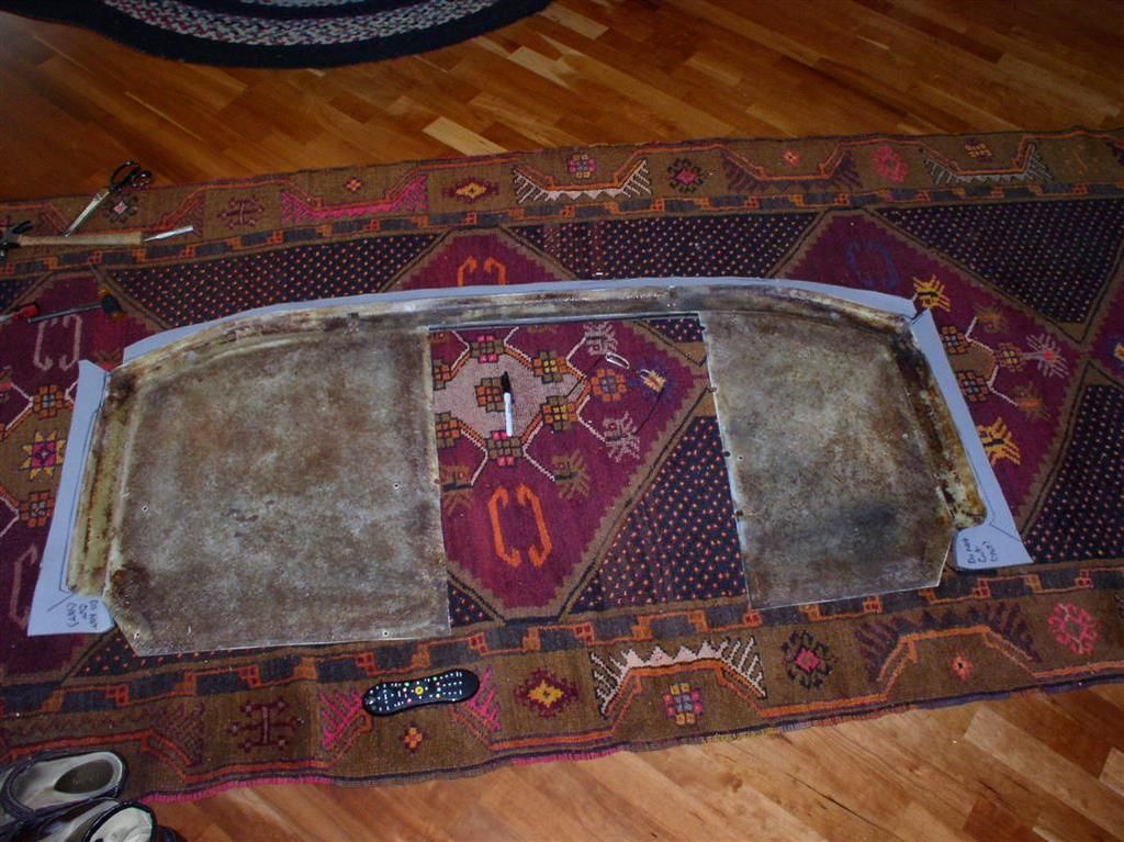
    Finally decided to get started on my "Reduced Hump Bulkhead Cover" construction. My plan is to have the center cover attached via Velcro, so I can just pull it off, and access the metal engine cover from inside, without pulling the whole big piece off.

    This project will be ongoing until I get a couple more parts for my ZF (on the way), and then will likely go into a holding pattern until I get the motor & transaxle installed.

    Anyway - I already had the reduced metal engine access cover, and all of the accessories (Sanden Compressor, and 1G alternator outboarded) - this was fabricated on my last build. You can see pictures on about page 4 of this thread.

    Now I am starting with a reasonably OK rear bulkhead cover. It had some rips in it, so it would have needed reupholstering anyway.
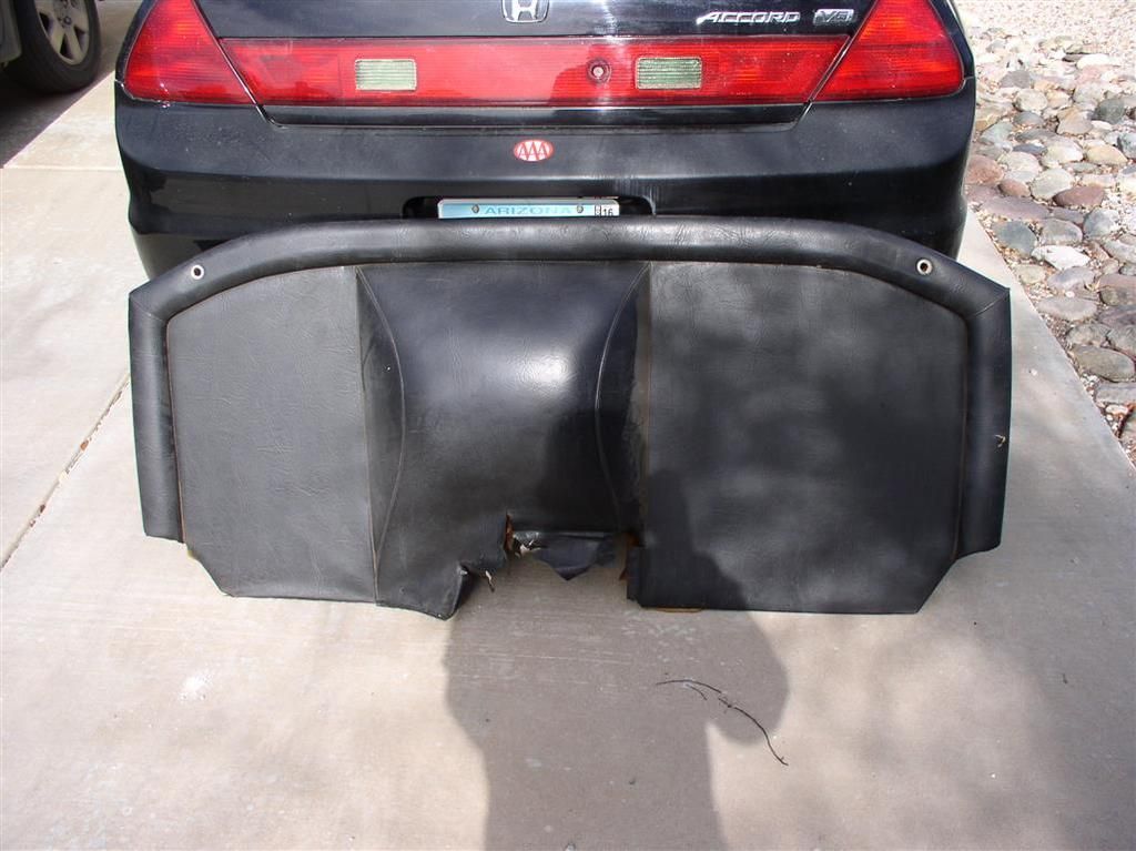


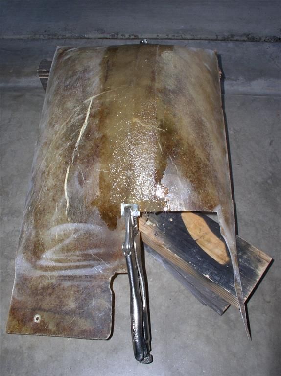
    I stripped off the upholstery and foam, to reveal a fiberglass cover in good shape. I kept the vinyl to match the fabric, and to help me with the sizing when I go to reupholster it.
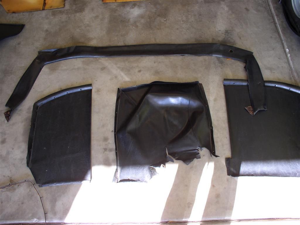


    I plan to do the upholstery on the big pieces (the outside) myself. I will probably take the "hump" part to a professional - maybe. It seems like the hardest part will be sewing the seams accurately.

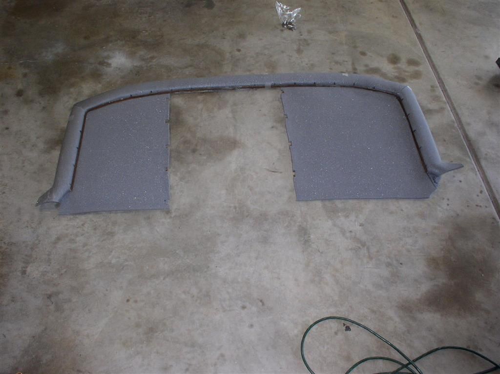
    I stripped off all the foam on the inside and outside, and hit it with a wire brush on my angle grinder. It cleaned up nicely.

    Then I cut the center section out with my angle grinder.

    I was worried about the thing breaking at the top, so attached a temporary support piece.
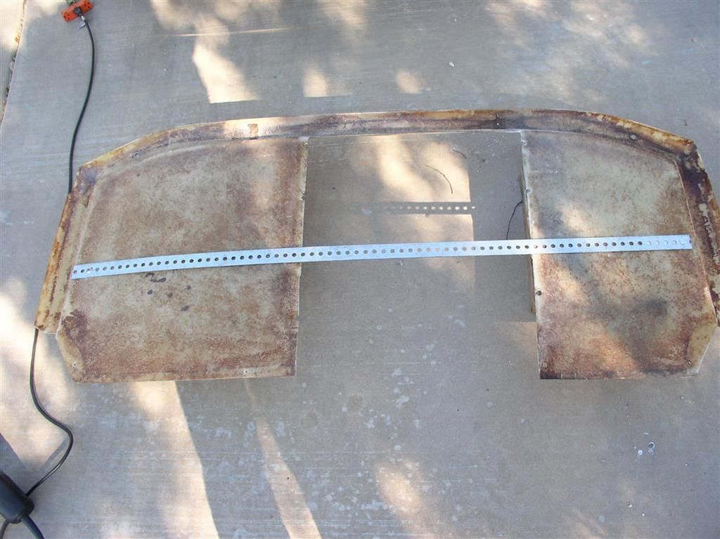


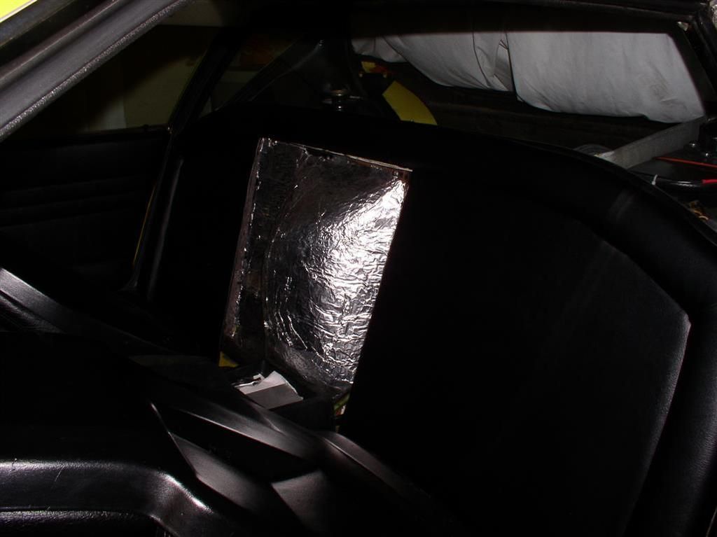
    This part fits nicely in the car. Now to start on the hump tomorrow (when I can get out and buy some sheet metal and fiberglass resin. Maybe I will look for foam and vinyl at the same time.
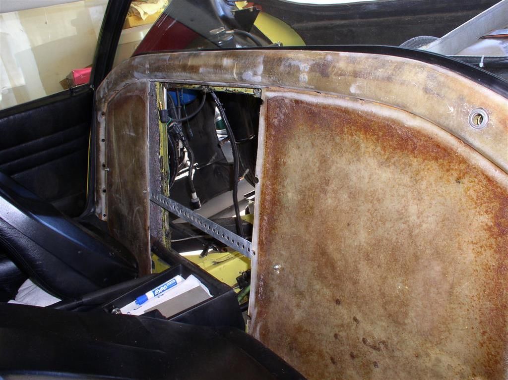


    Here's couple more pictures in a slideshow.... Watch this space for more pictures.

    Slideshow of Reduced Bulkhead Cover Construction....

    Rocky
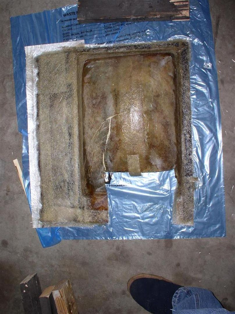
    Making a little more progress. The main panel is now fully cut and aligned. I am starting to realize this is a bigger project than I thought it was....

    I also found out I can easily fit 1" Styrofoam insulation behind the fiberglass bulkhead panel (in the permanent part).

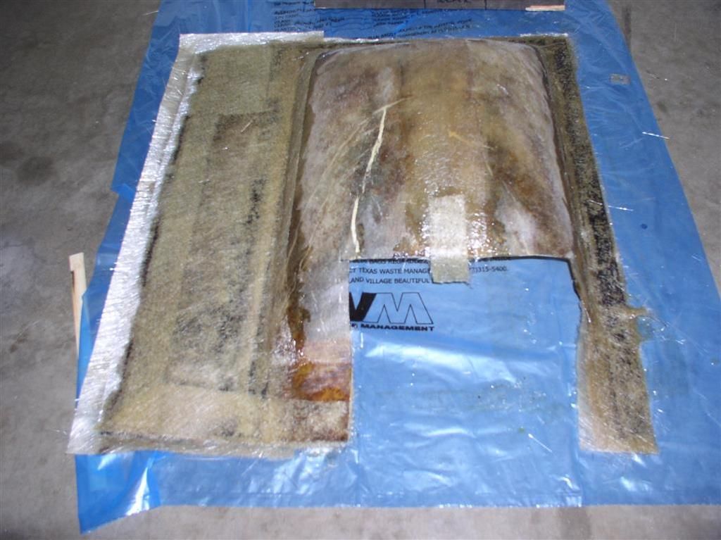
    The Hump is glassed over (joined).


    Rocky
    Still waiting on my ZF Parts... Talked with Lloyd (RBT) today - he's checking on my shipment. This wait is AGONIZING!

    More progress on the bulkhead cover (thanks to my wonderful wife!)

    Bulkhead cover cut out....


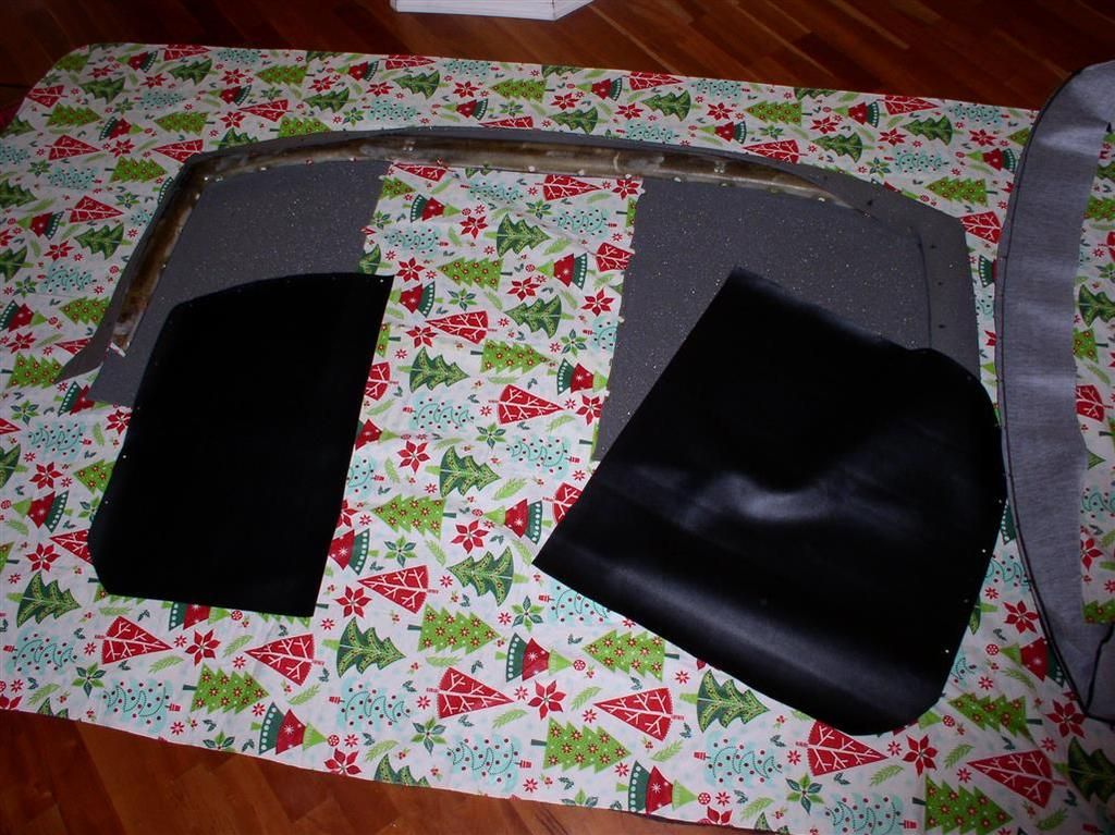
    "Scrim" attached.... (See, I'm even learning some of these upholstery terms!


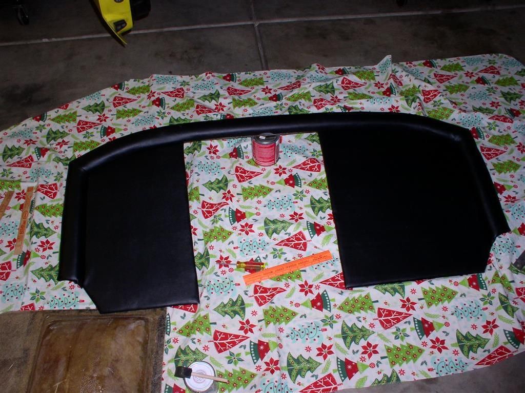
    Sections are laid out.... Note that the piece on the right is the raised "rim" cover. What you see is the vinyl turned inside out - there is a lot of flip-flopping of the materials.....


    Here's close to the end product.... It's a little wavy because I have not stretched the vinyl, and glued it to the backing yet. The technique (my technique, anyway) is to install the pieces, clamp them all with the metal rim & screws, and then stretch it, and glue it to the fiberglass board.

    Joe, thanks for the compliment. The work took a long time, but worked out to be "relatively" inexpensive so far....

    * Donor Bulkhead Panel $60
    * "Scrim" and Vinyl $57
    * Fiberglass Resin $15
    * Fiberglass Cloth $15 est.
    * Grommets $ 6
    * Weldwood Cement $10

    * Being Extra Nice to Wife - PRICELESS!

    You will note I attempted primarily a large, flat area.

    I am not really thinking I'll do the "hump" - I'm going to take it around for quotes... Hoping to do that for ~$150.... (we'll see).


    Yes - Part #215 - Synchro Spring...

    Attachments

    Images (1)
    • PN_215_Synchro_Spring
    quote:
    be a "standard" and available


    I've searched for ZF parts, and mostly they are building automatics now (it seems) and I have not seen anything that looks right.

    I did talk to Lloyd this morning, and he told me the part was on it's way. So I am hopeful.

    I also hope to upgrade to a higher (lower?) ratio 5th gear (.642 vs. the current stock .704).

    Scope creep continues!

    Rocky

    Add Reply
    Post
    ×
    ×
    ×
    ×
    Link copied to your clipboard.
    ×