I am, and I'm sure every one else is as well. Thanks for taking the time to document the process. I'm anxious to see how it comes out. As I posted earlier, I opted for the SACC unit, which I'm hoping is a bit easier installation and works about as well. I read that the feel (?) was "totally different" but never quite established if different is better, worse, or just different.

@Ed Harbur
I was hoping to find documentation like what I’m doing right now about the procedure… It would’ve made the decision easier or maybe harder…

Once everything is done, I’m gonna let somebody with experience with Pantera drive it to assess how the brakes and Powersteering and all the other stuff i did to it came out!

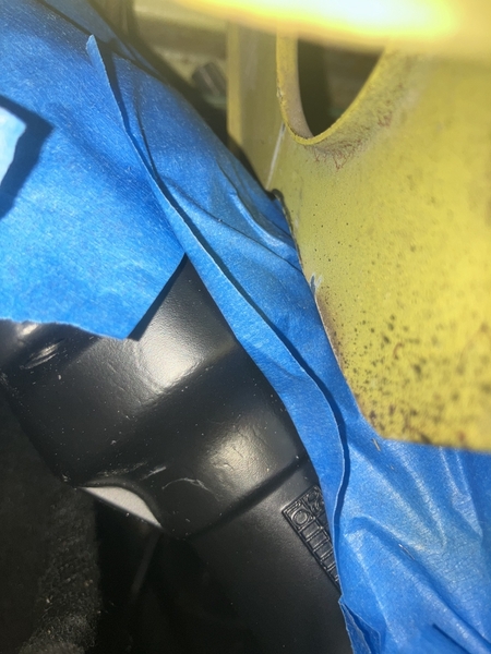
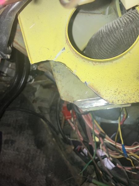
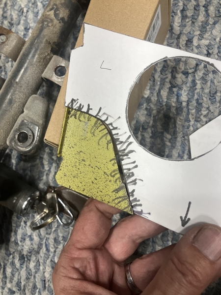
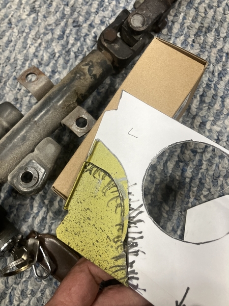
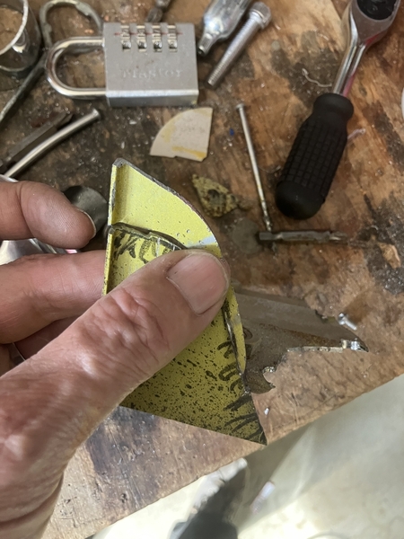
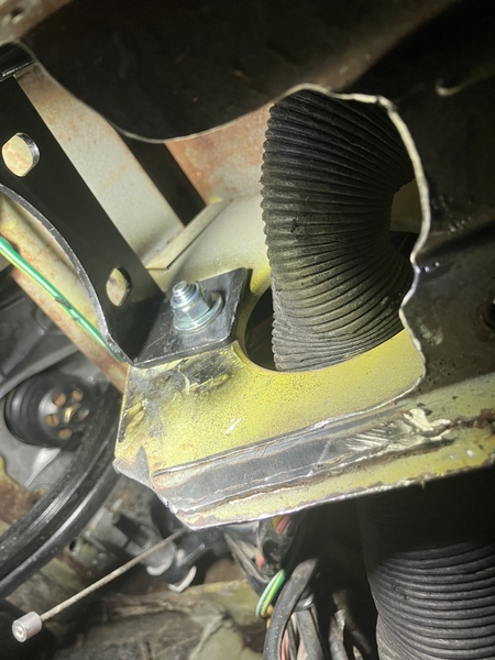
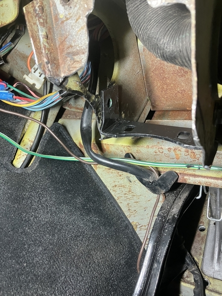
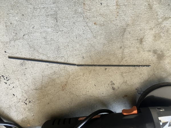
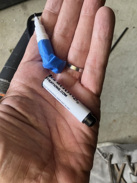
I made a little bit of metal dust! Make sure you put some old bed sheets down…

It’s going to be very hard to get this stuff out of the carpet!

IMG_0845

Attachments

Images (1)
  • IMG_0845
Last edited by LeMans850i

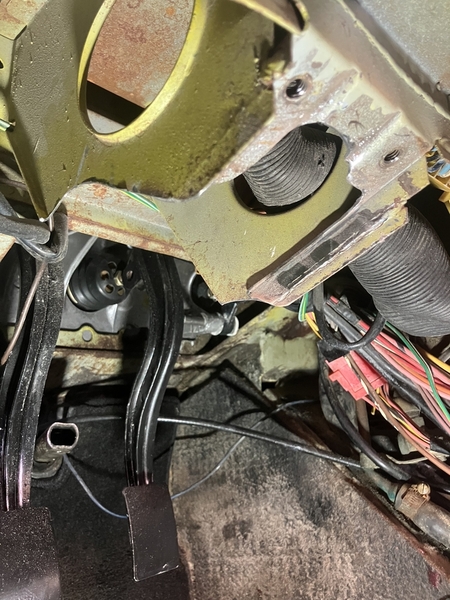
@Ed Harbur - I bought a SACC Power Steering Unit and it was pretty easy to do the install.  You had to do a little cutting and drill a couple of holes.  I also made a spacer for the bracket to take up some space.  I can take pictures of the final install if you need some more pictures.  I just followed Scott's instructions and everything went well.  Very sturdy install.  Larry
20230105_21093920230105_21095720230121_191338

Attachments

Images (3)
  • 20230105_210939
  • 20230105_210957
  • 20230121_191338

the left mounting bolt trapped by bracket in the back is a nuisance! You have to disassemble the rear bracket to bolt it to the dash structure…

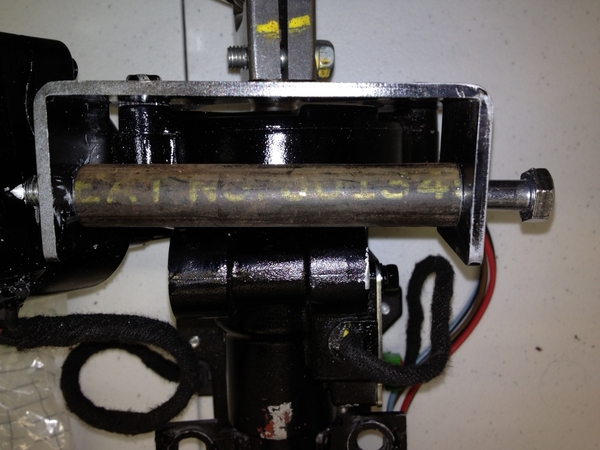
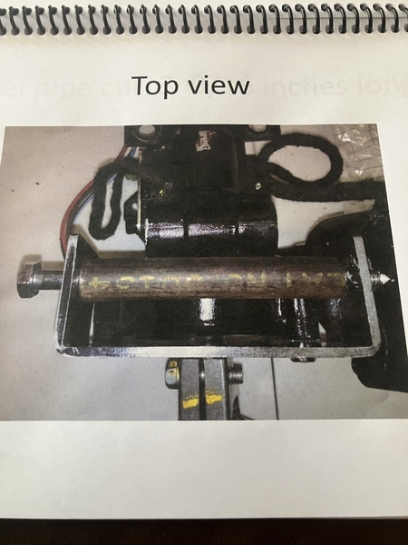
IMG_0850 @ davidnunn did a modification to his setup using a long bolt reaching through both mounting holes, nut on the electric motor side and made a spacer so It can be  proper torqued down!
the solution was adopted by Gerry in his manual!

IMG_0861
Bolted it in with front 2 bolts… seems to clear, can jiggling & wiggle… after I take it off I’m going to look for witnesses mark on the tape….


Note how high the electric motor is tugged up under the dash!!

IMG_0859


IMG_0854

Attachments

Images (6)
  • IMG_0859
  • IMG_0854
  • IMG_0850
  • IMG_0851
  • IMG_0852
  • IMG_0861
Last edited by LeMans850i

I have questions… Bring your best answers if you could please!

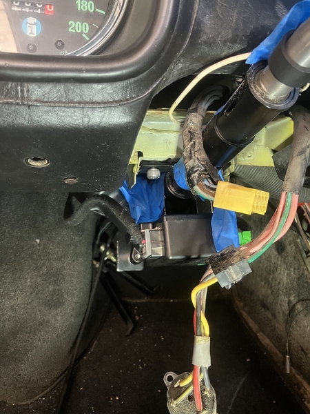
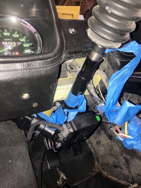
The steering wheel shaft is about one finger thickness, away from the dashboard!

IMG_0862 That’s not enough to have the steering cover on it it takes at least two maybe 2 1/2 finger thickness between center of the steering shaft and the lower part of the dashboard. The mounting surface of the two ears welded to the steering shaft I absolutely flush with the bottom of the dashboard structure… So there is no angle change going on. It’s just flat right on itIMG_0863


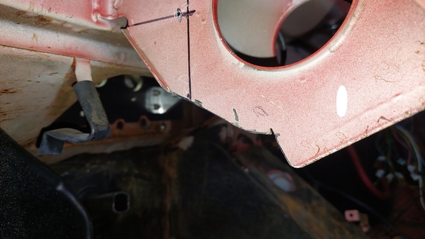
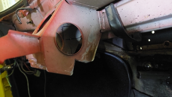
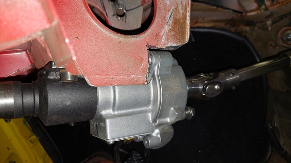
nothing is twisted. No pressure on anything that’s just the way he wants to sit right now… The cutouts I made today have about between one and 2 mm clearance to the power steering box… I have not drilled the two holes for the rear bracket!

I think, a small movement on either of those attachment points would make a usable difference in the spacing. I’m looking in the front.

IMG_0864

how does all this angle change affect the steering  shaft  after  it…?? ?The  hollow  “D” shaft coming through really does not have any movement in it. Am I going to stick everything together and see what spacers do I have to put in the front…

or enlarge the cutout in the back and make pie shaped spacers for the front.. which still doesn’t mean the steering shaft is gonna end up where needs to be… It only has one joint! I only can change the angle after that joint (pivoting at this joint)!

any input?


(I think just stick everything together loosely and see where it ends up - The good old rolling the dice)

Attachments

Images (3)
  • IMG_0862
  • IMG_0863
  • IMG_0864
Last edited by LeMans850i

There is a difference in the clearances you ask about between the  types of dash the car has, i.e., the dual pod or the single pod. In fact, the version of the single pod that the European market cars is a little different then the plastic version used in the '74 USA cars. The Euro version is a pretty thick fiberglass.

The front mounting bracket in this case (EPS installation) really needs to be made with slots (about 1" long) rather then single round holes, so that there is some adjustment, in and out (front to back).


It also needs to be made so that the wheel mounts as high as can be with no shims and able to be shimmed down to adjust the angle to your liking with bolts long enough to accomplish the adjustment. To me that is obvious and an indication that sufficient experimentation was put into the design process.

The left rear mounting bolt is the toughest one to get in, no question. In my case I had to use a flanged hex head bolt where I used Allen socket bolts in the other three spots.

That is actually a back and forth process where it is necessary to modify the new bracket in my view. My mounting bracket started as a square plate with four holes. Then evolved into slots for adjustment front to back.

This is probably the toughest part of the fit to the car. The trimming of the sheet metal is very minor in comparison.


I actually went through that (adjusting the closeness to the dash) before the EPS developed (or ever existed yet)  in that I was going to a Momo steering wheel and the adapter gave more room and I wanted the wheel closer to the dashboard so I had remade the mounting brackets with slots.

This actually showed in the angle of the directional signal rod in that it needed to be bent more for clearance to the dash when in the "high beams on position".

In fact, at one point I toyed with the idea of the telescoping column like the Corvettes have, but since I am the only one who drives the car I just set the location to where I felt most comfortable. In my case, that was as tight as I could get it to the dash board...but my thought is that the new column mounting bracket needs slots and that what you have is just plain an oversight.

Last edited by panteradoug

Larry- Thanks for the info and pics. Scott actually shipped my unit yesterday - MONTHS earlier than predicted, but unfortunately right before I'm getting my back overhauled so that I can actually get in and out of, and work on the car again. 6 weeks with no heavy lifting. Oh well! I will definitely take you up on your offer of a little coaching when the time comes, though.

@Ed Harbur posted:

Larry- Thanks for the info and pics. Scott actually shipped my unit yesterday - MONTHS earlier than predicted, but unfortunately right before I'm getting my back overhauled so that I can actually get in and out of, and work on the car again. 6 weeks with no heavy lifting. Oh well! I will definitely take you up on your offer of a little coaching when the time comes, though.

I found that laying across the seats from the passenger side, with the door open, feet sticking out the door, leaning up against the shift lever, was the easiest position to work from.

Here, the steering wheel quick disconnect really helps because the steering wheel is not in the car at that point.
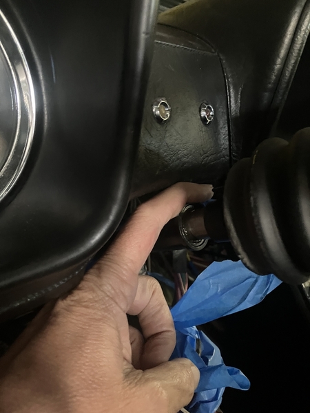
It is possible though, that I am permanently deformed as a result of working in that position?

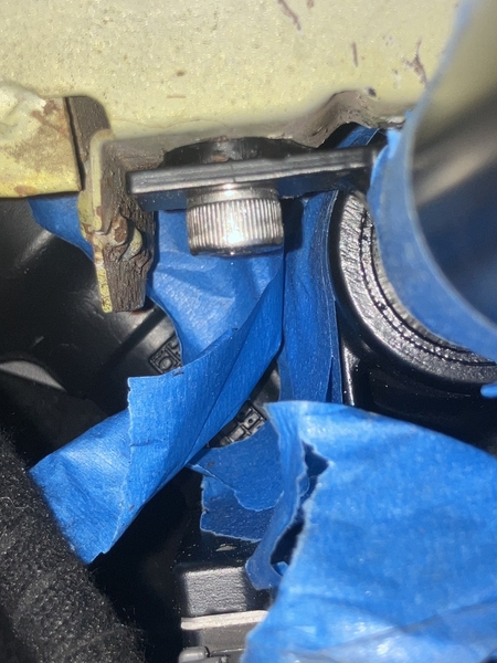
I'm curious as to what changed between the original steering column and the new? The mounting tabs on both are flush with the outer diameter of the column. Why is a spacer needed to make the column cover fit? I must be missing something. Some of the pictures at the top of this page are not showing on my screen. I did see in the write-up that the cover needed to be trimmed in places.
Last edited by tsolo
@tsolo posted:

I'm curious as to what changed between the original steering column and the new? The mounting tabs on both are flush with the outer diameter of the column. Why is a spacer needed to make the column cover fit? I must be missing something. Some of the pictures at the top of this page are not showing on my screen. I did see in the write-up that the cover needed to be trimmed in places.

I was asking myself the same question while I was making that spacer! And I’m thinking that it should fit the way the original steering column fit because the dimensions are the same. The front bracket is level with the tube as the original one, so the only thing that Would be in the way is the cut out !

I think if I go up in the back by 5 mm, the front probably comes down by 9mm

IMG_0901

Attachments

Images (1)
  • IMG_0901
Last edited by LeMans850i

Okay, I think I understand now. The original column mounted to the bottom plate with 4 bolts, so the angle was fixed. Now that the rear of that plate has been removed the angle is no longer fixed and you have to set it by the location of the new rear mounting holes. This is good information to have. You need to measure the clearance distance at the front of the column to dash prior to removing the original column. Then you need to match that distance when marking out the new rear mounting holes.

Could you reload the pictures at the top of this page so I could see them?

Steve

Last edited by tsolo
@tsolo posted:

Okay, I think I understand now. The original column mounted to the bottom plate with 4 bolts, so the angle was fixed. Now that the rear of that plate has been removed the angle is no longer fixed and you have to set it by the location of the new rear mounting holes. This is good information to have. You need to measure the clearance distance at the front of the column to dash prior to removing the original column. Then you need to match that distance when marking out the new rear mounting holes.

Could you reload the pictures at the top of this page so I could see them?

Steve

you’re absolutely correct! And that was something I did not know…
After enlarge the cutout, it just - well I would not say it fell together - but I gave it one push and then  everything was where it supposed be… so now I still have to check the steering itself, so nothing is binding and then have to mark the rear holes..

IMG_0830

IMG_0822

IMG_0841

Attachments

Images (3)
  • IMG_0830
  • IMG_0822
  • IMG_0841
Last edited by LeMans850i

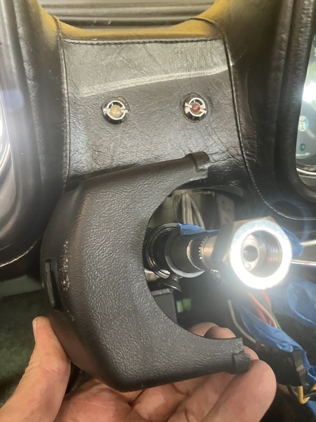
Just by dimensions, both steering column, the old one and the power steering column all the same length size with the joint location the same - everything should fit… But spending some time with the file and the vice (making an unnecessary spacer) and I knew I got something wrong! I was just trying to fix the problem at the wrong end. I don’t need a spacer in the front. I need more room in the back!

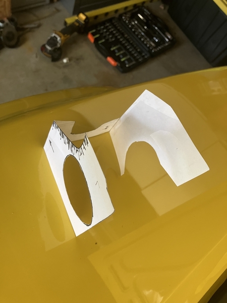
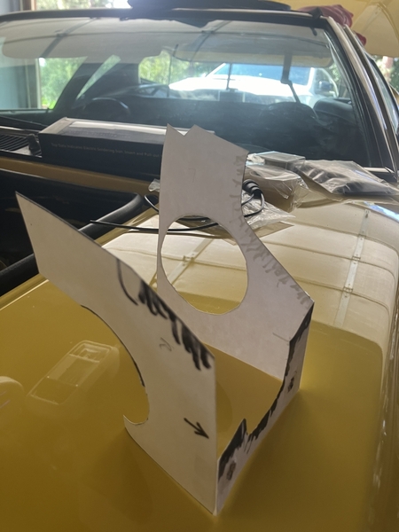
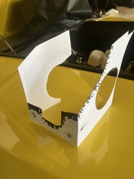
those templates are rough guides but definitely not something to count on. There are no measurements understandably whatsoever and everything was welded together by Luigi and Giuseppe. Maybe it was Friday - they’re all different! Measurements really wouldn’t help except measure from the dashboard down to the steering column (before you take the original one apart)  and trim the ass end until the power steering unit  fits! And it will fit!

I try to avoid sharp corners in my cutting because they would act as stress risers… the force to move the front wheels is still the same just the force to move the steering wheel is lowered..

Last edited by LeMans850i

Here is the next puzzle to solve…

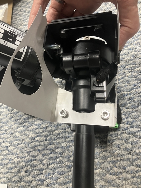
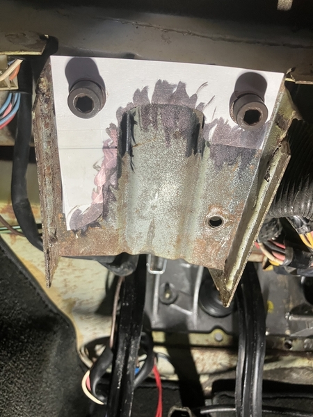
The black bracket it’s on the rear of the power steering… once you put everything in place and attach the front 2 bolts you can feel the holes through the back, there’s like a 1 inch slot on the top, but you can stick a finger in… One finger only!

the instructions it says mark the holes for the bracket and drill the holes…

I couldn’t do it with everything in place..

paint on my fingertip.. no… not enough penetration into the hole…

so put everything together and put it in place where it’s supposed to be then unbolted that bracket and tried to the best of my abilities to leave it in place exactly it’s supposed to be and unbold the rest of the steering and removed it In the hope the bracket stayed in position! It’s held by the 2 uprights I trimmed before… about 92mm apart… if I touch the uprights the bracket moves… not falling out but moving… so did the whole procedure again and this time I just use the red can to get the outlines and hopefully the hole…

now while writing this and looking at the pic I should have made a paper template… that might be another solution! Maybe more accurate than my abstract painting!

up to this point I had the Powersteering in and out approximately 10 times!

IMG_0915

IMG_0916

Attachments

Images (2)
  • IMG_0916
  • IMG_0915
Last edited by LeMans850i

Now here the @davidnunn upgrade..

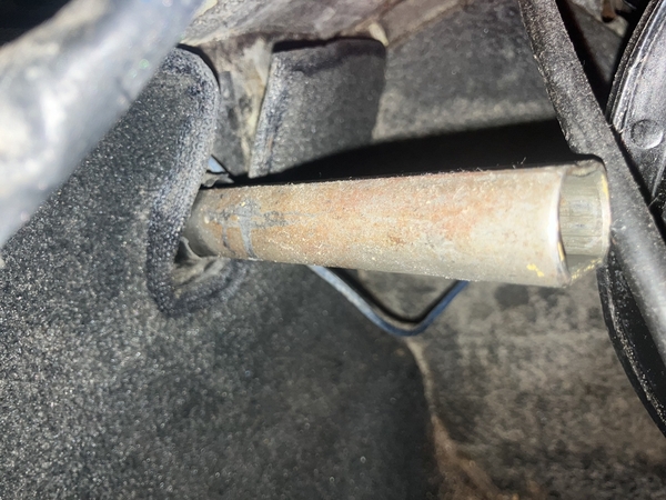
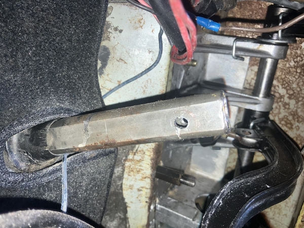
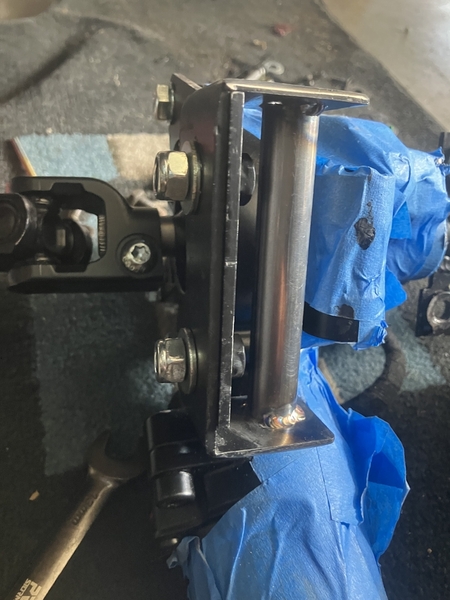
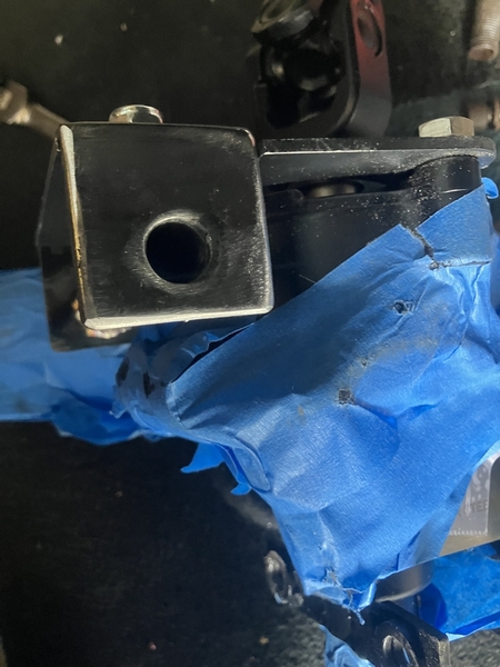
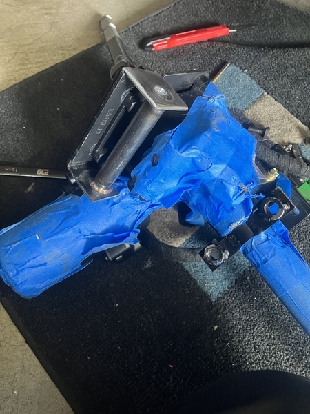
welded a tube between the two ears of the rear bracket so a long bolt can be used!

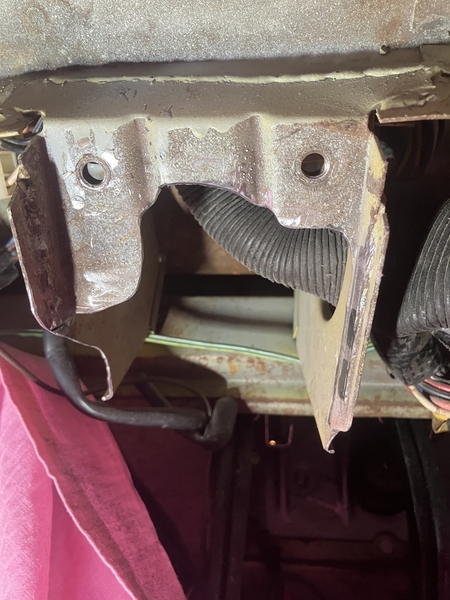
I enlarged the 8 mm hole to half-inch, so I have some movement to tighten the Powersteering down relaxed but solid!

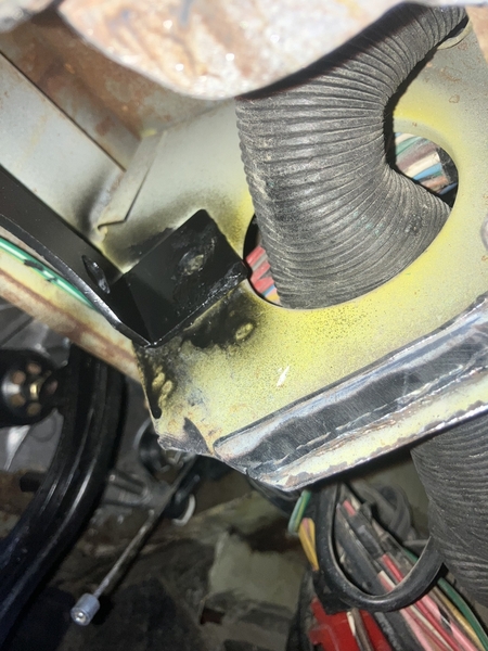
also got rid of all the sharp corners on the brackets, so it’s easier to move so it finds the place where wants to live!


IMG_0936

IMG_0935

IMG_0934

Attachments

Images (3)
  • IMG_0936
  • IMG_0935
  • IMG_0934
Last edited by LeMans850i

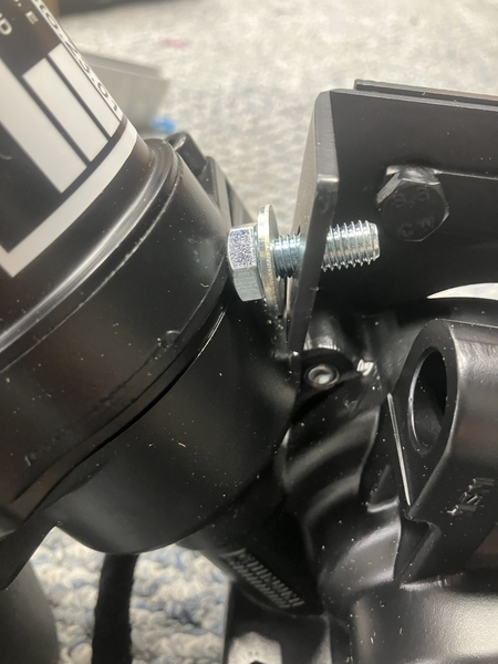
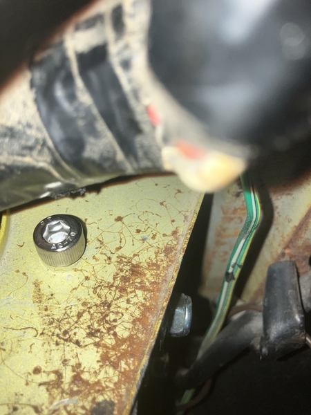
Now. Close to the end of the mounting endeavor …. Balancing and holding the power steering unit so many times, trying to locate the front nuts that are welded in the structure to get the right angle with the bolt and not cross thread - I got the idea to change to studs instead… So much smarter so much easier! By a mile and a half!!!! Especially if you have to add the steering column shroud as well!
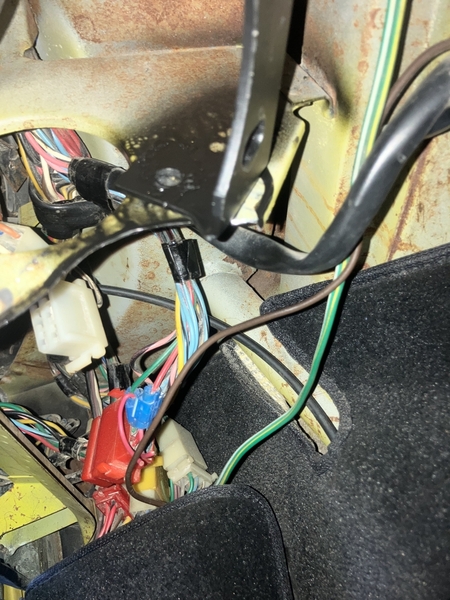
I got the 8mm bolt in the back in but it was a fight with the 1.5” thick 50 year old  stiff wiring harness… but it fits!!!  Tomorrow I measure the proper length for the bolt… take everything apart, fix my lower hollow, steering tube, make everything nice and spiffy, and reassemble it!!

honestly… I’d rather do 3 pedal boxes - Hell -  I’ll make that four!!!

When it started on Friday a week ago I said I should be done by Sunday. Well it’s going to be Sunday but a week later… Wow
I guess I’m getting old…

IMG_0941

Attachments

Images (1)
  • IMG_0941
Last edited by LeMans850i

Well, the grip length needed is a hair under 105mm sheet metal outsides with EPS in… but I’m sure there a a couple mm squeeze left in the setup.. On the nut side is not much room….. not sure if I need to file the nut down to be able to fit a washer.. ( washer is 1.5mm thread pitch 1.25mm )

105+1.5+1.5+5 (4turns)=113mm

going to run with a 110mm and hope for the squeeze factor…


IMG_0850

Attachments

Images (1)
  • IMG_0850
Last edited by LeMans850i

My friend, Riley, who used to be on the forum but has since sold his Pantera about a year ago, had added the SACC power steering unit to his '73, and I drove it once and thought it was great, especially with the adjustable boost.  He installed it himself, so it's doable.  The only reason I haven't added it to mine is because, with my very big feet, I drive mine for the last 30 years, barefooted, and the small electric box was mounted to the left of the clutch, and I was afraid I'd keep knocking my foot into it.  I've had several surgeries on the foot, and I was afraid, but would still love to do it and take some strain off of my 71 year old shoulders.  I will speak to Riley this afternoon and ask him to weigh in on this topic from first hand experience. 

I drive my Pantera barefoot as well for the same reason. I read something somewhere that led me to believe that there wouldn't be an interference issue, so I decided to take a chance and order the unit. I should have it this week. I won't be able to install it until mid-summer however. I can certainly look at it, though, and I'll report in as soon as I learn anything. Perhaps we need to start a support group of some sort.

Add Reply

Post
×
×
×
×
Link copied to your clipboard.
×