
While you are doing this kind of work, there is one mod I really like. Look toward the bottom of the page where I mounted large eyelets through the frame:

http://www.rc-tech.net/pantera1/valance/valance.htm

I have already had a chance to use them easing the car off the trailer at the interior shop. The ramps were not that great and this was a great point to attach the cables to. BTW the airbags were very helpfull for ramp clearance:


On to the door frame surround on the left. Bad rust under the trim:


Just a little note about the weld in that last pic, between the rusty patch and the rivet hole. It looks like a butt weld, but it is not; it's a lap weld. More on this in a bit.

The rust on the edge where spot welds are is so bad, I can't see where the welds are. So, I went to the inside and scuffed the paint off so I could see them:


I still cut them on the outside however. Here I cut a small part out to see how the inside structure was made. The inner sill is kind of folded back around and spot welded to the inside of this rusty piece, but up closer to the roof panel. If you look closely, you can see the spot weld divots. If I cut any closer to the roof panel here, I will be cutting into it. This gives me an idea; I can use that inner panel as a guide for my panel nibbler's jaws. It will guide me to cut away just the right amount of this rusty metal:


Here you can see this worked pretty well:


I had to finish up at the fore and aft ends with a dremel. Finally the rusty strip comes off:


Again I am fortunate that the rust formed from the outside in. The inner structure is solid:


Pay attention when you make the repair pieces; this is 16 gauge steel:


Now to fix this bit. Cutting in tight corners can be difficult. I actually save my cutting discs when I have worn them down to 1 or 2 cm. in diameter. I use them in tight spots like this. I only get a few seconds of use before they're gone, but they do the trick.


See what I mean about this being a lap weld. Again, I’m lucky that the rust has only affected the outside; the inside is solid. I can clean this up and weld in a small patch:


Making the patch and test fitting:


Finally the pieces are clamped in place, tacked, welded, and smoothed:


Needless to say, I will NOT be using pop rivets to hold the trim on. I’ll use low profile stainless button head screws.
Last edited by ufo-low
Here is something I did not expect: the smallest pieces are the hardest to make. Without the special tooling the factory had, it is really difficult to copy some of the complex shapes, bends, curves, and folds of the factory pieces.

Here is one of the most complex areas of the whole car; what I call the upper B pillar junction. This is where the heavy structure of the lower B pillar ends, but a smaller section extends up to the roof line. It forms the frame of the cockpit back glass, the rear quarter window glass, and the upper back part of the door frame. The top fore-most part of the rear quarter panel, the top of the cosmetic door striker panel, the inner panel facing the engine bay (the one just above the gas tank), the rear wheel house longitudinal stringer, and the firewall cross member (with the upper seat belt fasteners), ALL come together in this area. It is very prone to rust. I have over 100 pictures of the work on just this area.

First to get the lead off:


Starting to see the metal, and rust, under the lead:


Now to cut out the rusty parts, bit by bit:


About 3 inches of this inner panel, below the quarter window, has to come out too.


I try to cut panels between spot welds, it is easier to put them back together that way:


I have to cut through these panels in my way, to fix the structure underneath. I spend quite a lot of time looking at this, to minimize collateral damage. If possible, I want to put these cosmetic pieces back on.


This corner where the cockpit back glass fits is trashed too:


Finalizing the cuts:


And it is off:


This piece I will clean up and reuse:


Next episode; cutting out the rusted structural parts. Stay tuned!
Last edited by ufo-low
If you have never had to repair this part, these pics should give you an idea of what you are in for. It will give you one of those “what were they thinking!?” moments. Here are four strips of light metal, two of which extend down to the top of the B pillar. Open to the rear where the tire can throw rain water, salt, and road trash at them. Just behind is a stamped in welding access hole that looks like it was designed to catch said trash, and trap it inside the structure where it can do maximum damage. Ye Gads!

Here I have already scuffed off the worst of the rust, and I have to ink mark the spot welds just to see them:


Now I have that junk out of the way, I can start cleaning up this area:


And get an idea of what this weldment looked like originally:


See where I have started to cut these pieces out:


Once you get the rusty junk out of there, and clean up the rest, it starts to look more manageable.


Here is a cross section cut of the vertical B pillar extension:


Another tip; keep all pieces of the damaged parts you cut out, no matter how bad, until the repair is completely done. They give valuable clues to guide you in reconstructing the parts. Even if you do not copy them exactly, in many cases I haven’t, they show the intent of the designer. Some times you can simplify, or even correct a weakness in the design, and keep a problem from occurring again.

Next episode: making the repair pieces and welding them in. Stay tuned!
Rod.
Last edited by ufo-low
Now for the fun part - putting it back together again. As I mentioned, there are 4 pieces to this weldment. I cut them off at different lengths, partly because that was where the damage was, and partly because it makes for easier repair. I labeled them and used a piece of tape to copy them. The tape is cut at the edge of each piece, and marked with a sharpie pen at the major bend(s):


Here are the repair pieces in rough form. Yes, it took a few tries to get them right. Notice on #4 for example, I left extra width so I could get a grip on it with my stretcher jaws. Cut the extra material off after I got the bend right:


This piece I will be saving, but I have to cut off this bit of rusty flange so I can make a new one:


The first piece to repair is the top of the cockpit cross member. I decided to do away with the pinch weld flange, as it really does nothing useful. The back glass gasket has plenty of flange to hold on to, and in this tight corner the flange kind of does more harm than good. If I find later that I need it, I can easily weld on a piece to replicate it:


Next to make a new piece for the inside of this flange; at the bottom of the rear quarter window opening:


While I’m in here, I am going to make a shield for this big hole. I brushed and vacuumed out the crud, and thankfully found no serious rust inside. I trimmed a bit off the flange, then fitted a simple metal shield:


I just want it to keep most of the crud out, but allow air in for evaporation. It is held with a single self tapping metal screw from below. I’ll spray some undercoating in the area later.

Here I have trimmed this inner panel flange piece and adjusting the fit:


This area is not easily seen, so I do not worry too much about making it pretty:


Now to weld it in:


Next to start repairs on this weldment. Starting with piece #2, it is the first one to attach back on to the upper B pillar. That little hole is original, from one the rivets that holds the trim piece on. It is a pain in the butt; I either have to leave it or recreate it. I chose to leave it, and I have to be careful about welding near it.


Here I pause to test fit the quarter panel piece I cut out of the way earlier. It hits the edge of piece #2 just a bit, so I’ll trim #2 off a tad.


Back to welding:


I had to use a small screw to align the rivet hole in this new piece with the original. There was so little room that a nut would have been in my way, so I used a split pin instead. The screw and pin were removed after the welding was done; they were only there for alignment:


Finally I have enough of the welding and smoothing done so I can spray some zinc primer in there:


Now to prepare the quarter panel piece to go back on. I welded some backer strips on it:


After some smoothing, it looks much better. There were also some dent puller holes just below this area which I welded up also:


Finally I have to weld in a strip of metal where the striker’s cosmetic panel meets the door frame; this was badly rusted out:


After touching up a few pin holes and smoothing, I pronounce this job done:


Time for a beer!
Last edited by ufo-low
Next I will detail my repairs to the A pillar area on the left (driver’s) side.

Here is kind of a “before” picture. To the right is the left (driver’s) door, which is toast. To the left and below are the front fender and outer rocker, respectively, which don’t seem too awful bad, right? Just a few rust bubbles, right?


Wrong! Here is what lurks underneath:


I’ve already started cutting out the rusty metal, see how bad it gets as I progress:


Here is one of those “what were they thinking?” bits.


These small assemblies I guess are meant to be splash shields, and I think there was some foam or rubber like material in the little groove. They may have done some good when new, but not long before the elements take their toll. Why not put it on the front of the A pillar where it would have done more good, and possibly have been serviceable? We’ll never know.

Next I have cut a piece out of the front fender; not only was it rusty, but the A pillar and contour panel behind it are rusty too.


With this out of the way, and the bottom of the A pillar cut off, even more damage is visible:


Notice the lap spot weld, where the mid-rocker joins the inner front wheel well surround. I had no idea the wheel well surround metal extended this far back; it is a good 3 inches rearward of the door opening.


This piece of the outer rocker / door sill has to come off because it is in the way; I will end up reusing this piece:


With that out of the way, I can cut out the rusty inner wheel well surround metal:


This pic shows the difficulty of repairing a damaged unibody. The floor pan metal above and below the stiffener is the same piece of metal!


The “floor pan” extends in one piece all the way out to join the mid and outer rockers at the flange weld. The stiffeners are spot welded to it, inside and out. If I needed to replace the floor pan, entirely, I would have to cut out all the spot welds to remove those stiffeners. I didn’t count them, but there must be hundreds. No thanks.

Back to cutting out rust and cleaning up the area:


Next episode; making and installing repair parts. Stay tuned!
Rodney.
Last edited by ufo-low
Here is my solution for the rusty floor pan between the stiffener and the flange weld. I’ve cut out the rusty piece, and made a replacement that will be welded to the stiffener. It will give me a new surface make a new flange weld on. I tried to make this in one piece, but could not get that curve at the front right, so I made it in two pieces.


This is test fitting and trimming:


Next to make repair pieces for the mid rocker and wheel well surround:


This is 16 gauge steel, so harder to work with. There are some tough compound curves here too:


This is the only easy piece:


Even a small portion of the inner rocker was rusted through, so I cut out a rectangular piece:


and made a small patch:


This access hole on the interior had an ugly rusty patch on the edge. This is only cosmetic, but I fixed it anyway:


I made the patch for the mid rocker overlap to the rear, just to add strength and be sure I had solid metal to weld to. I cut the rectangular piece out of the outer rocker because it was damaged, but it made a convenient access opening to weld through.


Next up; a slight departure from originality. Stay tuned!
Last edited by ufo-low
I have to side track my own thread a little. I had reached the point when I had to install my roll cage support stiffener, and this is not going to make sense unless I back up a bit to explain.
Some time ago, I decided I would put a roll cage in my car. Mostly for occupant safety, but also thinking about possible track day adventures. The SCCA rules describe the requirements, and I also looked at the work of other Pantera owners. (Thank you all for documenting your work; you know who you are).
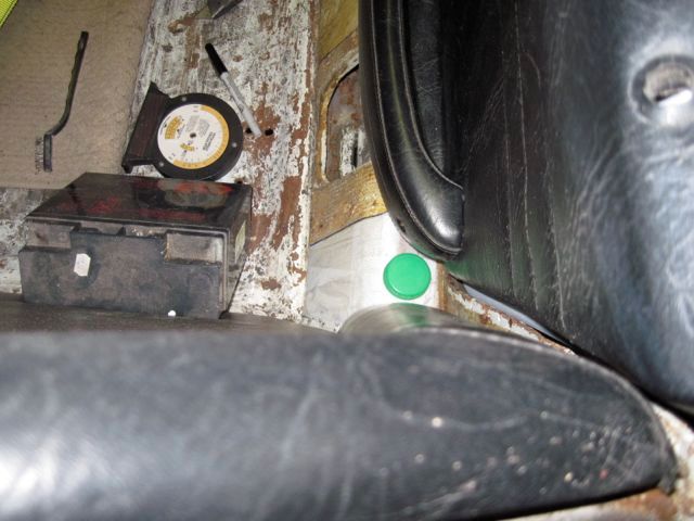
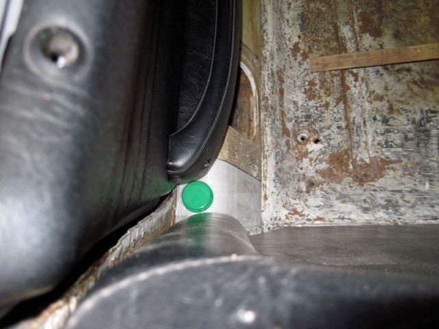
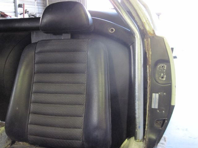
I started by locating the end points of the main hoop and side hoops. You can see I’ve temporarily installed some of the interior trim. The green marker in these photos is a milk jug cap, which just happens to be 1.5 inches in diameter, the size of the cage tubing:


I did not have an idea how to make the tubing pieces fit, and I imagined that trial and error would take a lot of time and effort, along with a lot of mock up material. After giving it some thought, I decided to try a 3-D CAD model. Essentially, I would make a 3-D model of the car’s interior, and then draw a roll cage to fit within it.

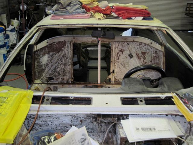
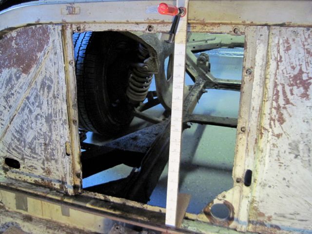
These next pics show the set up of the X-Y-Z coordinate reference. Nothing more than some wooden yard sticks clamped in place inside the cockpit, and another yard stick with a level taped to it, free to move about and measure things.


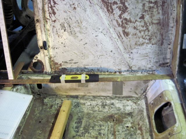
Except for the mounting points, I did not measure where I wanted the roll cage to be; I measured the constraints. In other words, I measured the things the roll cage would have to clear. One point at a time, I filled in a table of X-Y-Z data points, with notes about what it was I had measured. I suppose this took a few days of shop time, a “shop day” being usually only a few hours a day. When I entered this data into my CAD program, the result was a crude, but accurate, model.

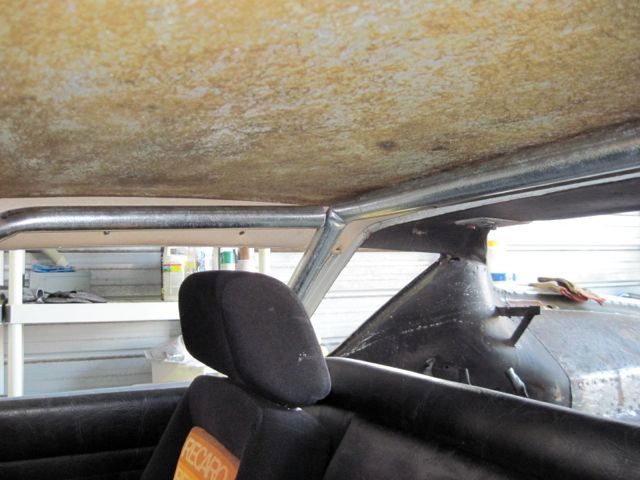
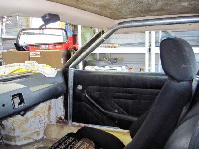
Once in the CAD program, I could model the roll cage, and try different designs. I let the computer figure out the lengths of the tubes and angles of the bends. I bought some 1.5 inch electrical conduit to use for a mock up. The bends kinked kind of bad in the mock up, so I’ll have to take care to avoid that in the real thing. The mock up verified for me that I had a good model, as these photos show:


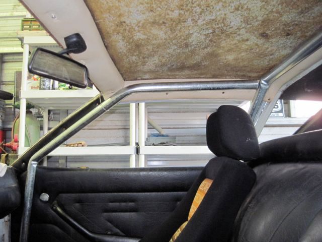
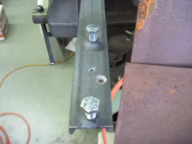
While doing this I was thinking about the mounting points. Attaching a tubular structure to a unibody is not easy. Most designs use a steel plate contoured to fit on the inner rocker and held with multiple small bolts. I decided to use a different approach; a structural stiffener made of channel steel, inside the rocker. The roll cage will be welded to short segments of the same material, and these will bolt to the stiffener. The inner rocker metal will be sandwiched in between. These pics show it better than I can explain it.

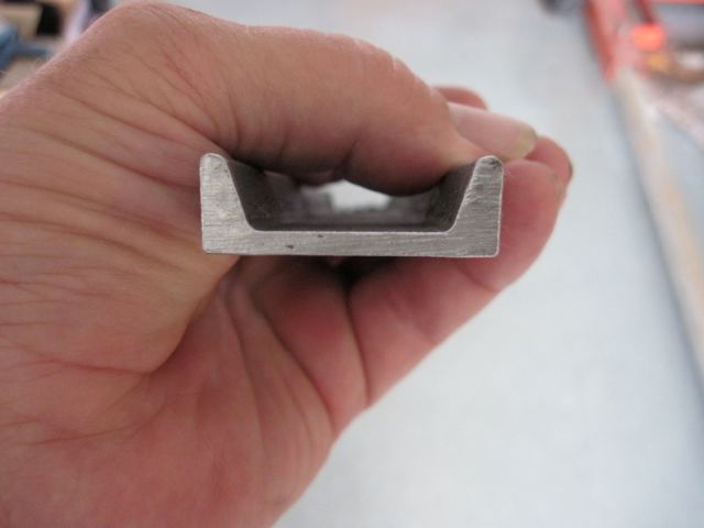
The channel steel stiffener cross section:


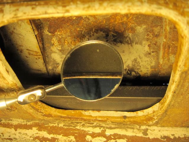
The edge of the seat belt retractor opening is rolled in. I had to trim maybe 2 mm off the inside edge to allow the stiffener to sit flat on the underside of the inner rocker sill.


The mounts are two 3/8 - 16 grade 5 bolts at each mount, with nuts welded on the back side for more threads:


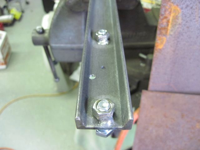
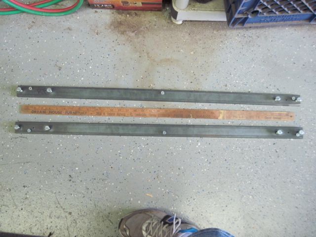
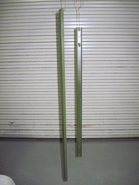
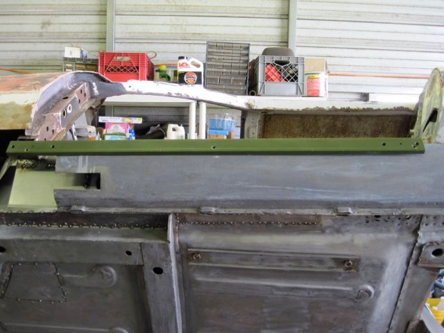
Here they are complete, one for each side, before and after painting:


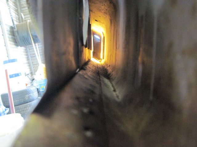
Now, back to where was I? These stiffeners can only be installed with the front of the inner rocker channel open, as mine was thanks to all the rust repairs. Once it is installed, the opening is welded up, and it does not come out again.

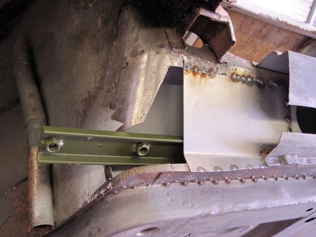
Here is the inside view (this pic is the right side, while I’m working on the left; did not get a pic of it):


And finally the installation:


Standard disclaimer of liability: I can offer no assurance that this design offers any benefit or meets any specifications, or is suitable for any specific purpose, yada, yada, yada. If anyone chooses to copy it, you do so at your own risk. Nuff said.

Next episode; closing up the rocker and finishing the metal work.
Last edited by ufo-low

Add Reply

Post
×
×
×
×
Link copied to your clipboard.
×