On my Pantera I had one ball joint that didn’t cooperate and I had to take the whole assembly out… with A-arms to be able to give it the proper 2 Hammer treatment… sometimes there is just not enough room to inflict the shock that is needed for it to let loose… ☹️
![]() Yeah, nothing that a torch can't help...And good news, everything from the upper ball joint and down is findable. Even the stub axles are available (Fiat 125/1300).
Yeah, nothing that a torch can't help...And good news, everything from the upper ball joint and down is findable. Even the stub axles are available (Fiat 125/1300).
Lee! BAD NEWS.....is that the steering arm that you'd be wanging on and heating is NOT readily available. IIRC, it is a common part......but uncommonly modified by DeT dudes.........rebent to fit car.
Somewhere in a post(?), the 1300 arm (or whatever it is) as stock is shown next to the Goose modified piece...... Not the same!
Just watch out for good paint!!!
Cheers!
Steve
FWIW, I tried everything to remove the tie rod from one of my spindles and eventually gave up using the normal processes--puller, PB Blaster, heat, BIG hammer, more heat, combination of all the above, etc. So, I cut off the tie rod (that metal is HARD) close to the spindle and started drilling and grinding as centered and as carefully as I could, using only the hand tools I had available. I worked on it a little at a time that winter until there was only a thin layer of tie rod left that I could finally remove. You can see the galling that took place before my time and probably kept the tie rod from being easily removed, I'm guessing. I don't think those hammer marks are mine, but they could be. It's been a while...
Attachments
On Tuesday, May 7, 2024 at 03:58:25 AM PDT, The De Tomaso Forums <alerts@crowdstack.com> wrote:
| == To reply by email, write above this line. == |
|
New Reply By rlee63a4
|
| Goose 8MA642 Refurb and RepaintReply by rlee63a4
FWIW, I tried everything to remove the tie rod from one of my spindles and eventually gave up using the normal processes--puller, PB Blaster, heat, BIG hammer, more heat, combination of all the above, etc. So, I cut off the tie rod (that metal is HARD) close to the spindle and started drilling and grinding as centered and as carefully as I could, using only the hand tools I had available. I worked on it a little at a time that winter until there was only a thin layer of tie rod left that I could finally remove. You can see the galling that took place before my time and probably kept the tie rod from being easily removed, I'm guessing. I don't think those hammer marks are mine, but they could be. It's been a while...
This post contains 2 images.
[ View Reply ]
|
| The De Tomaso Forums
You received this based on your notification settings. You can adjust your settings or unsubscribe anytime.
|
Finally got tierod heim end disconnected with 2.5 ft braker bar. Still messing with getting tierod joint separated...
Removing upper a-arm nut closest to driver...looks like even if I could get it off that putting it back on will be major pain...is my assessment about right?
WOW!!! There is nothing on this car that should be "that tight" except for a big nut or two inside of the ZF!!! That's some serious metal bonding! I think the thing to do is hit anything you are looking at taking apart, and hitting it with PB Blaster a few times and work on something else for a week!!!
That upper a-arm nut is tricky. Isn't that where the long shaft goes from side to side? ....or am I thinking rear upright....... Are there holes in foot wells???? CRS today....been working on insulating shop and it's 80 degrees+ up there....can you say sweatball!!!?
I have very few pictures of this stuff to share....pre-digital camera for me! ...still trying to develop the practice of taking pictures with my iCamera......! Crazy!
One bolt at a time!!!
Steve ![]()
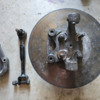
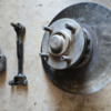
Living and learning...probably would have been a lot easier to get right front apart if I'd done it while still attached to car. However, given where I am, the wheel hub/steering knuckle/assembly in picture spins freely with no grinding, no noise, and no 'wooblyness'...should I still pull apart and change bearing? If so, should I just wait until after I reassemble until right front? The two nuts on the inside of wheel hub are being pretty stubborn as are the 4 bolts on the outside of the hub.
Have gone thru parts in parts manual and on forum. Does this look about right?
Tie rod ends - 2x4117875 (an easy $10 replacement appears to be a Delphi TA650...anybody used this?)
Ball joints - 4x5882118 (best suitable sub?)
sway bar bushing - 2x4084841 (best suitable sub?)
rubber stabilizer support bushings drv/pass (60020036/60020037) - ???
rubber mounting for shocks 60000020) - ???
rubber buffer for shocks (60020033) - ???
Attachments
Since you have it this far, I'd at least pop the bearings out and see what they look like for wear. Could be just fine! Clean, add new grease and reassemble.
As for taking the rest of the bits off.....unless you are replacing the rotor, it would seem like your fasteners are still doing their job! Impact tools are likely in order................gently!!!! Machinist on standby!! ![]()
Ball joints: Do a search on this site for references of good "no mod's required" pieces. I know I've seen the posts.....and guys have found the good ones....and they reference the "where" they go on the other cars that use them. I just can't recall and didn't write it in my parts book! Duh! Goose uses same joint upper and lower according to my notes.
Sway bar bushings.... Try search also. But I think whatever you can find in the aftermarket for the size bar you have may need to do..... Could be a Fiat/Alpha part......?? (Book page 7 lists it as FIat 1300 pieces)
Sway bar end link bushings: Sleeved rubber bushings similar to shock bushings. If what you have is still good.....be happy!!! Hunt for steel sleeved bushings could be unicorns....but I know guys have found such bushings......in the size you need??? Your mileage may vary. Slim chance the vendors like Wilkensen and perhaps Stock at PCC could have them...
Shock bushings: There are some new ones floating around out there but they are crap. Soft gummy rubber that the steel insert pushes right thru and in 6 months they look as bad as what you probably already have! These are steel sleeved versions..... Again, search on this item as a topic as guys have cut new ones out of more modern stiffer rubber and pushed them into place.
Shock damper: Carello sells some....I cut in half...used small section...other shock providers likely do as well.
I was lucky as my car didn't need everything here.....shock bushings were worst...had metal on metal! Of course shocks were toast also! Different subject.....
Search on grasshopper!!! You're getting there!
Steve ![]()
Thanx Steve...to get to the wheel bearings, due I just need to remove hub? To do so, do I take out the 4 bolts on the outside at the base of the hub and the circlip?
Behind the BIG snap ring and aluminum dust cover you will find wheel bearings and retention nut(s).
it is special!!!!! Similar to Pantera in that the nut is swedged in place and you will need to unswedge it with nail or small punch! Could even be a LH THREAD on one side…..CRS here! FIAT nuts…..
once nut is off rotor and hub slide right off!
be careful of the hub and area around dust cap! It is aluminum and can get forked up very easily….so exercise more patience and caution!!!!!
Steve
So, if I understand you correctly, if I get the nut off under the aluminum cover, and given the two pics of the brake disc/wheel/hub assembly above, I do not need to remove any other nuts and bolts from the brake disc/wheel/hub assembly to get to the bearings? Basically the hub attached to the brake disc will just slide off?
Yup!
Hopefully that simple! Nut can be a pisser.....go easy!
Steve
Attachments
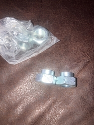
So Lee! You are now a bonafide importer/seller/reseller of foreign nuts??? ![]()
![]()
![]()
Noteable is the "markings" on the LH nuts to help mechanics know what the dealio is on them for proper removal/tightening!!!
S
Thanx, continuing to work nuts on hub. They are incredibly tight.
Of course the ball joints I ordered are 1.5mm to wide in diameter. Tie rods were ok.
I can only say to search this website for the info on BJ's that fit properly. You do not want to be turning down castings or hogging out cavities that are already thin to begin with! They have got to be out there somewhere......!
Those nuts shouldn't be tight, but because they are staked (they are staked right?) you need to unstake them before they will come loose easily. So what you have is a lock nut on the tapered(?) outside of the nut......holding it in position. Post pictures! ![]()
When you tighten the nut the first time, you only putting perhaps 10ftlbs of torque on them IF even that much. I'd need to dig up the torque specs for a 68-69 Mustang/Cougar to see what this needs to be. It isn't much!!!!
Steve
PS I drilled my spindles for cotter pins and immediately discovered that getting to the pins in the recess of the hubs, was a big PITA! Putting a slight curve in the pins helped installation.......but that's about it! Sorry no pic's.....dark ages before digital.......! ![]()


