[QUOTE]Originally posted by Mangusta:
I want to see what an allen headed nut is....!
Here's some (if the post works....)
Attachments
Images (1)


quote:Originally posted by Mangusta:
... My plan was to yank the heads which would allow my son and I to lift the remaining short block up onto an engine stand from where I could then remove the pan. Well, easier typed than done!
Rich,
If you have the time to put together a simple diagram, I would surely love to compare it to a couple of jackshafts up here that are still waiting to be installed! I missed an opportunity of another club member who installed his on Sunday! He was helping me on Saturday and hadn't known I was running into dimensional issues!! Ooops!
I'll put my pulleys back onto the shaft after I pull it all apart again, and see what the pulley center to center dimension is and go from there! It can't go back together the way it is.....
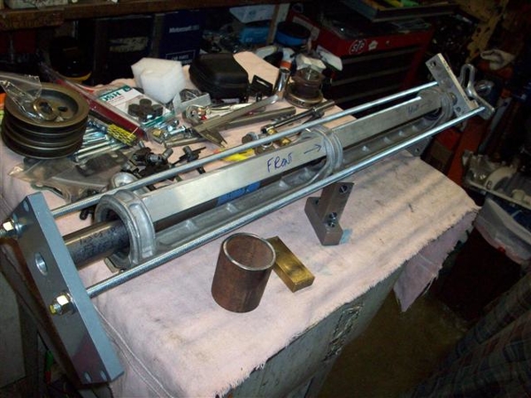
OK, just like Playboy wouldn't be the magazine that it is without pictures to go with the excellent stories, here are more pictures of what I have been rambling about!
Here is some catch up from two weeks back! ( A coupe of repeat pictures here.... oops!)
Pulling bearings from the shaft. Much discussion about whether these should be a slip fit or a press fit! Pulleys and nuts hold them in place..... OTC puller set purchased off of ebay, reasonable import stuff.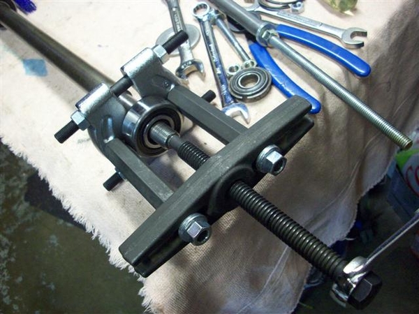
Here I'm pushing/pulling a bearing through the rear hole to burnish it a bit, and to make sure that they will go through! I pulled a bearing through each hole at least twice. Thin coat of anti-sieze was used.....that stuff gets on everything.....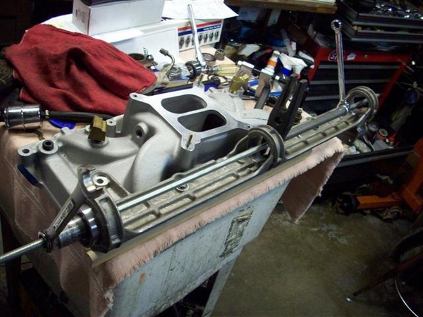
I had to be careful not to put TOO much pressure on the bearings as the jackshaft bracket would distort! So when ever possible I pulled from the center hole to the rear or the front...not the entire span front to rear.
I have not cut any short rod for doing this....but it would come in very handy!!! Long rod= lots of nut spinning! You can see a long piece of steel that I had left over from making my extra rear shock support attaching points, to take up space fast!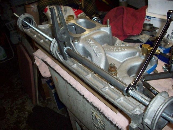
Here is a close up of the rear surface after the bearing has gone through twice. Once you get it moving, it goes just fine. Not a slip fit!!!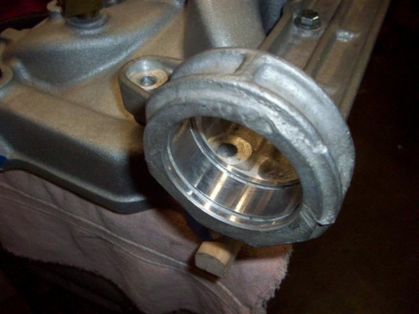
Here is a problem area for me! Hex bolts just are not optimum for the two rear bolts in my setup. The fronts aren't a great fit either! Now my shaft has been remade....so I have NO idea if the diameter is proper or not.....your mileage may vary!!!!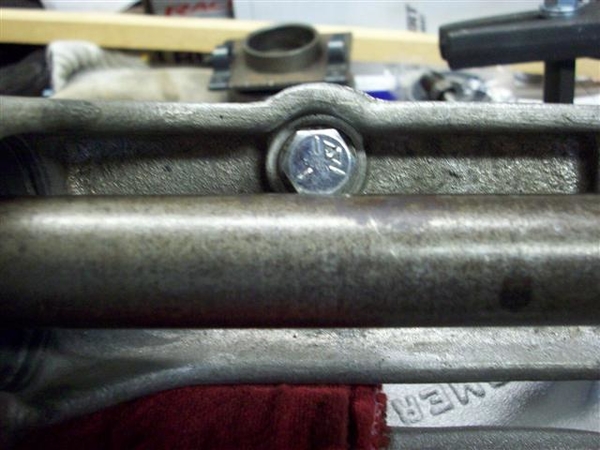
Here's what I mean! I'm switching to allen headed socket bolts. Not ideal but better. I will need to get a "long shank" 1/4" drive bit...short ones won't cut it!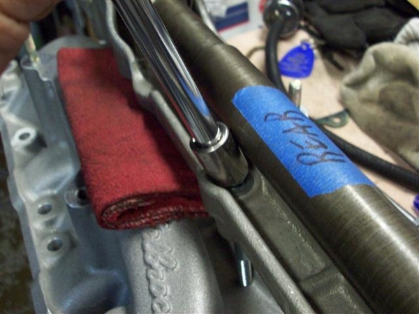
Here is my collection of misc bits and pieces that I had made up for pushing everything together. Note the pieces setting on top of the bracket, that I made from angle aluminum, to prevent the shaft bracket from bending under compression. They seemed to work....but it took a few sets of hands....tools are not finished yet.....to be one person things....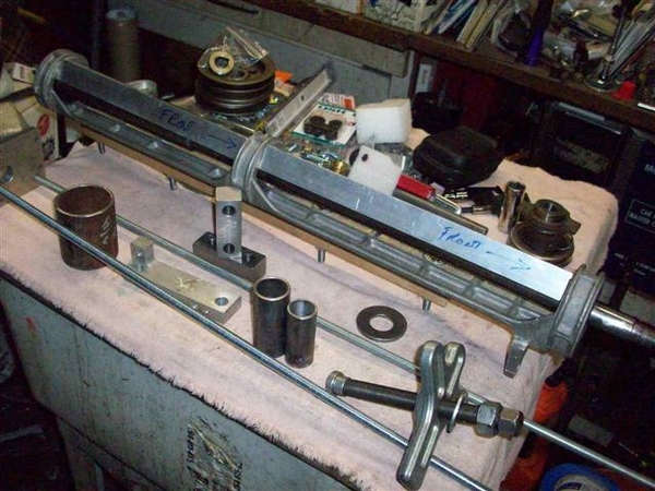
Closer view...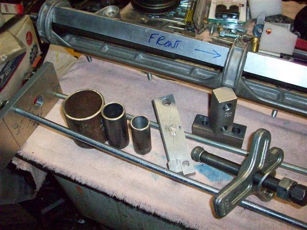
Large circular thing is for pulling rear bearing out. Circular thing in the middle is for pushing the rear bearing in, smaller circular thing is for pushing the front bearing in. Rectangular aluminum piece is for pushing on the circular things via the harmonic balancer puller. It needs a couple of holes drilled in it so that it will slip over the threaded rods when used for removing or installing... Pieces holding the jackshaft up are the drill blocks I had made up for dealing with my rocker arm stud holes. They worked great!!!
Front bearing installed. Note how it is just proud of the bracket! I think it needs to go in a tad....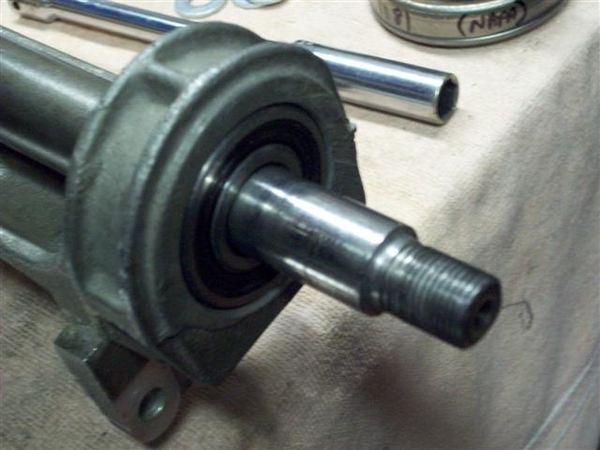
Rear bearing in place, snap rings installed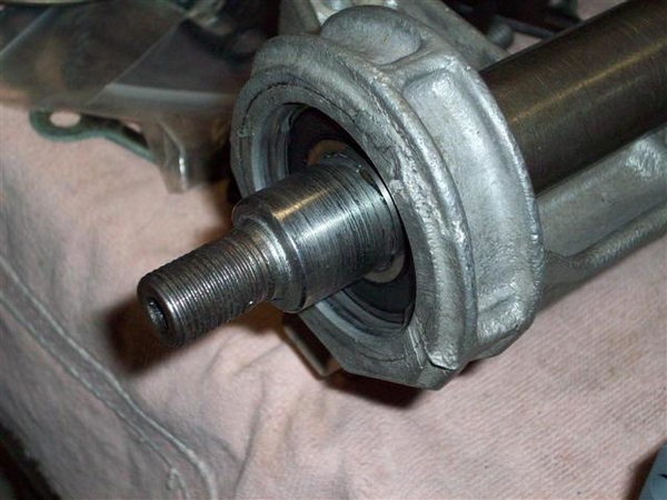
Center bearing removed...
Here is are shots of the whole installer thing assembled.. It was good theory..... Would love to see what a good bearing shop uses!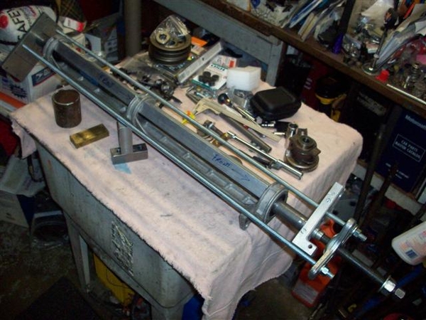
Front pulley installed. Note the amount that the shaft sticks out! Pulley is also hitting the bearing seal, so would need a small spacer which would push the pulley out more...yet it needs to go in about .125" to align with the water pump pulley! So I think push the bearing in 1/4" (cut shaft to fit...) use a 1/8" spacer behind the pulley to keep it off of the bearing seal....and should be great! Will need to revisit this dimension, as there is a recess in the back side of the pulley that will need to be accounted for.....also!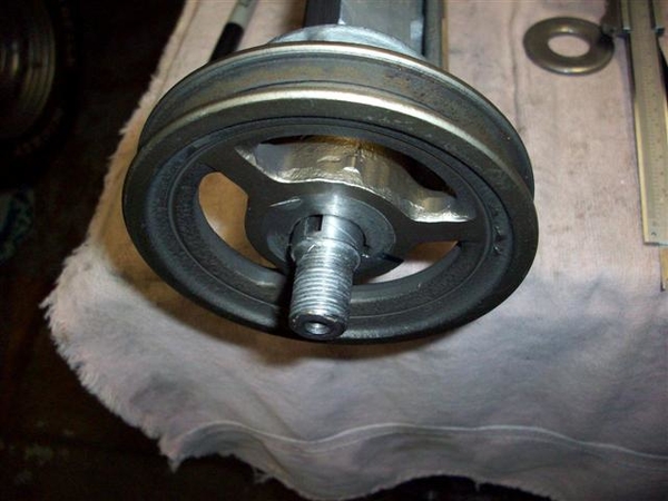
Another view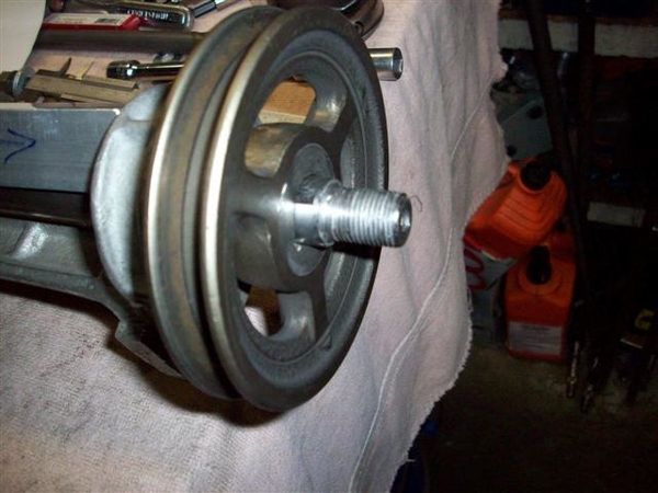
Outward facing sides of the pulleys and the various pieces I used to space and secure. Rear is on the left and front is on the right.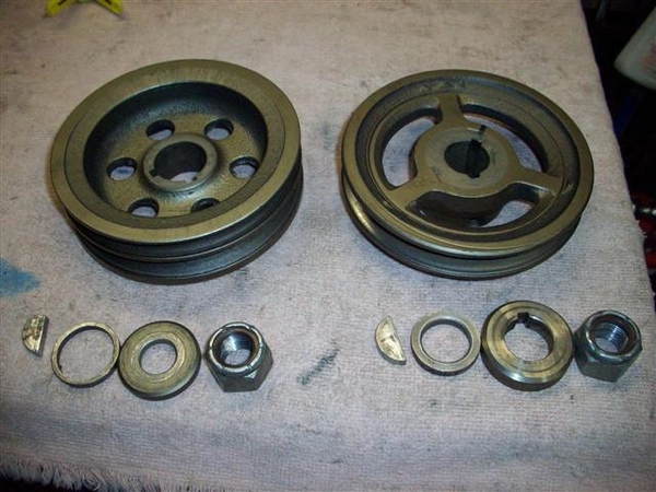
Inward facing sides of pulleys: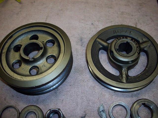
OK, next pictures are not for faint of heart!!!! Drilling on a mostly assembled long block.....!
Drill block in place, drill stop in place on drill bit. Worked nicely!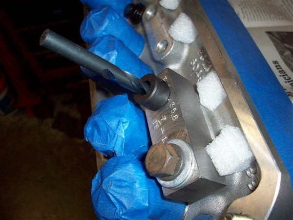
A bottoming tap, for getting more threads into a blind hole.. Note how the tip is not so pointy, as most of that point has been removed to allow the tap to go in the hole that 2 or so turns! Use solvent, WD-40, or even water when tapping aluminum to keep the tap from gumming up.....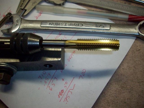
OK, enuf for me tonite! 16 holes are drilled and tapped.....on to push-rod guideplates again!
Steve


Well, this has been interesting!
For a bit, I was thinking that my shaft had been remanufactured to some odd dimensions......very odd....
Rich Chandler has been an immense resource to me here, in that he not only sketched out a rough but very detailed drawing of the jackshaft from his car, but he also dug out the pulleys, bearings, and attaching hardware and sent pictures of it all up to me! Oh, and he measured up the front pulley for me too!!! More on this later.....
In an effort to get some small stuff done, since big stuff is just not happening right now.... I took care of this....
I am using a late model 5.0 roller block, which has a provision for an oil dipstick in the side of the block about 3/4 of the way down the LH pan rail, to the rear. I used a 1/4" NPT (National Pipe Thread) tap and gave it a few whirls into the metal, and filled the hole with a brass plug I found in my junk, coated with some Permatex #2B Form-a-gasket (non hardening sealer).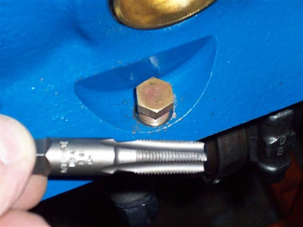
Since I was nearby, here is a shot of the drain hole boss that I had to take metal off of in order for the DeTomaso engine mount bracket would bolt up properly! Wasn't much, perhaps 1/8" of cast iron...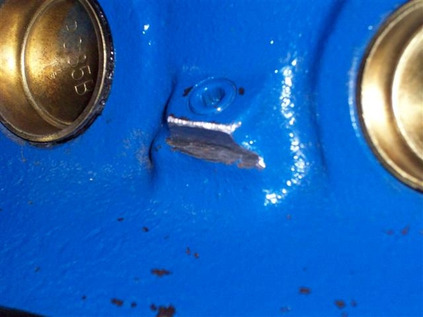
Next was the dipstick. Since I plugged the hole on the LH side of the block, (dipstick would run headlong into either the AC compressor or the coolant overflow tank...so opted for the stock location...
I am using a dipstick that came with the motor...found on many many many late model Mustangs, T-birds, Mark VII's etc. I cut the bottom section off of the tube first and filed down the sharp edges.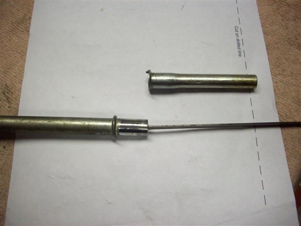
I then wiggled and forced it into the hole in my new timing cover....can't remember if this one came with a hole or I drilled it.....that's the problem with an engine build that spans years instead of weeks!!!!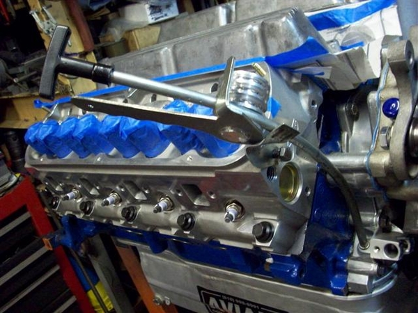
Using a crescent type wrench, I reformed the little mounting bracket on the tube and was able to get the metal to line up with a convenient 5/16" hole in the front of the head. Drilled a suitable hole in this little tab, cut off the excess and filed it all smooth....
Using a tubing bender I have I managed to put a slightly different bend on the main tube...not much....and also I dimpled the hell out of the bottom of the tube, where the retaining guide wasn't fitting the tube real well.....oops! Can't see it when it is installed anyway......just little dimples....little bends!
Dipstick still moves in and out "ok" but it is dry and will be better once oil is involved!
Here is a shot from the business end...what you will see when looking in the engine bay....I hope!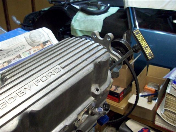
I also installed the one unique main stud that I need for supporting the Aviaad oil pan pickup. I didn't have this piece when I installed the crank etc. Sorry, no pic's yet.... And I put the oil pan up under the engine hanging by two bolts. Will button that up once I am done making a mess out of the rest of things up top! It goes on once the top end is all sealed up!
OK, while chasing bolts or something or other, I happened to come across a little adapter that I knew I had seen...but couldn't find! Was driving me nuts!!! I knew I got this in a water pump that we bought for our 68 XR7.....I thought I threw it in my steel bucket of nuts and bolts, but alas, I found it one shelf up in my brass recycling bits!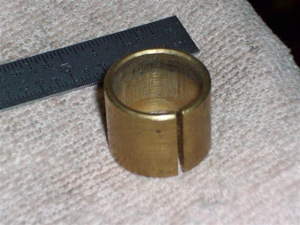
THIS is the part that adapts the DeTomaso water pump pulley's larger diameter center hole to the water pump center shaft, to keep it centered!!! The four mounting bolts won't necessarily do this on their own, although you could get lucky like I had been doing......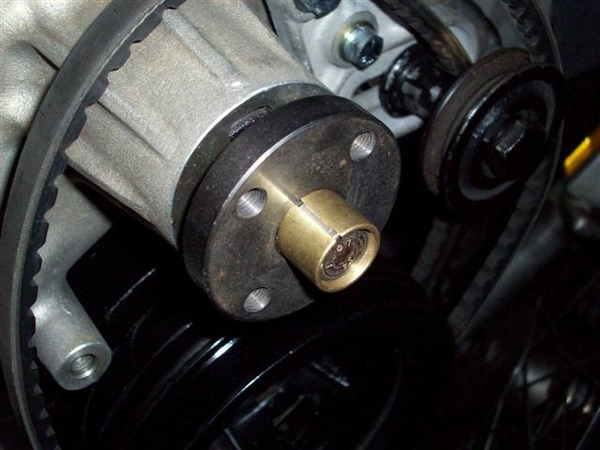
Pulley on!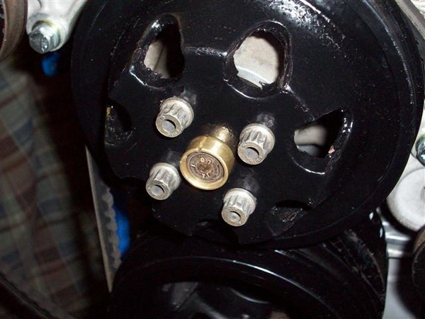


Back to my jackshaft pulley story!
I was just about to take the jackshaft apart again, and decided to check out some dimensions, since Rich has been so good to send them up! Turns out that they were all very very close! Over all length was just slightly different, but not too bad! So, I decided to play around with the pulley and see where I was... What I was up against was what you saw in the pictures a couple posts up, where the pulley stuck out too far unless I removed the spacers, which put the hub of the pulley into the seal of the bearing, as the pulley has a recess vs a protrusion.... It also has two holes drilled in it for set screws...told you this was an industrial pulley!!! If I cut the protrusion down to fit, I think it would cut into the set screw areas, so it either all comes off and I make a bigger spacer, OR, I do the RIGHT thing and get a pulley that is closer to the stock one!
Here are a couple shots of Rich's pulley!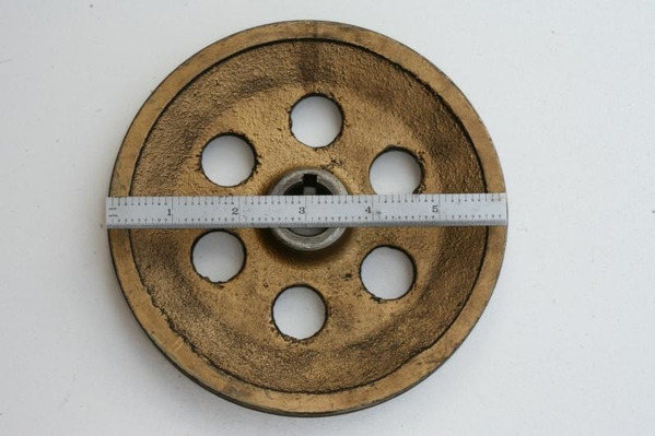
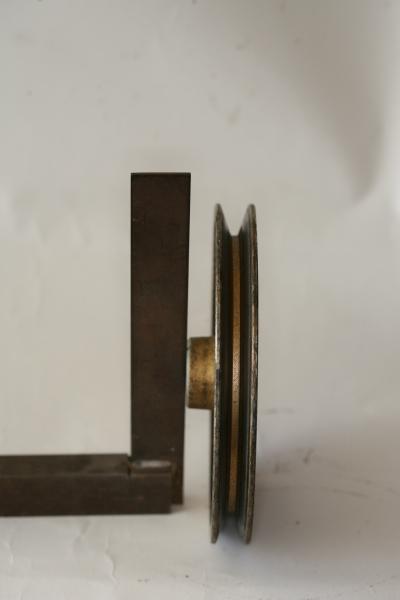
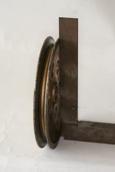
Here's what I figure happened many moons ago...about 1974 or so... When the third owner installed the Boss 302, they raised the engine frame mounts to allow the headers to clear the frame rails! When they raised them 1.5" this raised the original 6" diameter pulley into the body just below the cabin rear window! SO, they grabbed their industrial A/C supply catalog and ordered up a 4.5" pulley and cut it to fit..... Where the original is now, is anybody's guess, but I will tell you it WAS in Fresno....back then. (Still have not found the third owner.....who did all this work!) I did find the 4th owner and the jackshaft bracket and an air cleaner, but he didn't offer up any pulleys....I guess I could call and check anyway, but I think all he got from the salesman was an extra unused piston....!
So tonite, instead of working on stuff, I surfed and learned all about grey cast iron, ductile cast iron, maximum distance per minute of pulley travel....and that the internet is full of all sorts of crap!
Grey iron will work well up to about 4000rpms, ductile iron up to 6500. I believe these are continuous operational numbers, and that they would flash higher....but not 100% on that.... Ductile iron has more nodular metal in it, like cranks and rods.... Blocks and stationary stuff is made from the grey iron which has more graphite in it.... Told you...!
So, I just may contact a pulley manufacturer and see what it would take to cut one out of some billet steel.......Give them the dimensions and let them roll..... not sure if my dad would take this one on!!! We'll see!!!
Here is one last shot for tonight. There was talk of "allen headed nuts" and such before, used in retaining the jackshaft bracket to the engine. Here is a shot of one of Rich's fasteners....appears to be made from a 12mm diam socket head cap screw, that was drilled and tapped for 5/16"-18 about 3/4" deep! It is meant to be used with a double sided stud, as was used on the intake's center 4 holes (Two on each side) in the stock config from Ford. He says that they do not fit tight into the bores of the holes in the bracket, so there is still room for the bracket to move around a bit. They do not act as locators...
I thought it was a pretty neat deal! Have some pic's from another crazy Goose owner that came up with a rather novel aproach at this whole deal too!!! Will post later....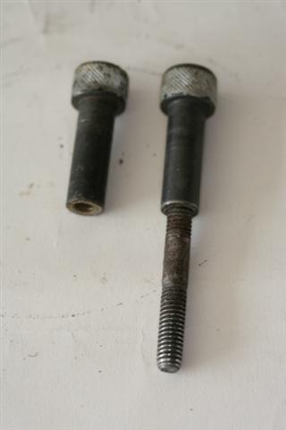
Out!
Steve


While the goose chase for a front pulley continues...progress today on more small stuff! Sheesh! So much small stuff!!!!
Called on new valve covers...that hadn't arrived while I was gone.... had been on back order from Ford, arrived at Rousch yesterday and shipped out today after the phone call to say "yes I still want the stinking valve covers!!" ![]()
Hit some shops and picked up more stuff...
HD vacuum hose and another 1/2" hose barb for the PCV line to connect to the rear of the intake.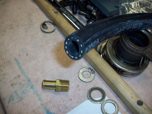
This stuff is HEAVY walled and shouldn't collapse. I had been using standard heater hose and it was looking like it had collapsed or had potential to do so...... This piece will feed the brake system, so no goofing around here!
Stopped by my clutch guy and bounced some things off of him....namely clearance on the pilot bushing. Mine was looking a tad galled, but I believe I had the clearance set a little tight. Shaft is .5904"ish in diameter so went towards .5940" on the lathe. Was a little tricky setting up a used piece in the lathe...but with a little talent helping me out, it came out great!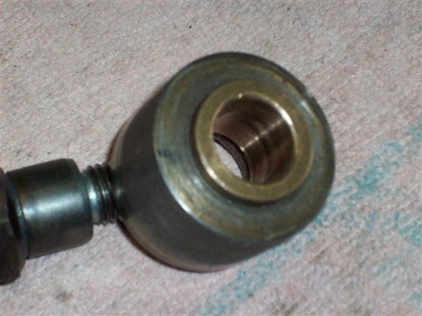
It was either take a light cut on this, or machine a completely new oillite insert....
Also tried to get a new (BCA 1625?) throw-out bearing but both my clutch guy and the other place I picked up my hose at were out! Ordered one....
Also got some small copper washers for the clutch and brake fittings...."just in case!" Worst case they are spares....they don't take up much room in the tool box!
While I was out, my bearings arrived from Giardi Bearing, for the idler pulleys.
This is what I took out of the idlers (new bearings on the left):
The bearing I took out was a 6003 which is too narrow. To take up the space, the PM (previous mechanic) used snap rings to take up the slack! I had pulled the bearing out and replaced them with the same...and put the snap rings back in.... Since I have learned so much about bearings....I looked into a larger (wider) size and sure enough, a #63003 2RS1 was available! Ordered three so that I had a spare...just in case... "they're small!" Pricey little buggers!! Ran me just over $30 each! ...but they did deliver to my door!!!
Used my assortment of sockets and such to press the old ones out, cleaned out the dirt, lubed with anti-seize and pressed the new bearing back in place, reinstalled the snap ring...like new!!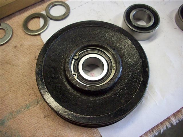
Mounted both idlers back up to the mounts and confirmed proper line up. Had to work on the bolt for one side as it didn't move in and out of the bearing easy enough for my tastes, so just dressed it with a file and polished it up with some worn 320 wet/dry sand paper.
Back to the Sharks game! Tied up, overtime!
Ciao!
Steve


Osofast,
I checked out those pulleys and at 5lbs for a 6" pulley, that is one lot of mass! I didn't see a V-belt on that page, but didn't get too far either....thanks for the idea though!
I've checked around a bit and it seems that machining something out of steel or T6061 aluminum wouldn't be all that difficult, just time consuming....
OK, back to the Goose chase!!!
Progress today in the spinterogino dept. (distributor!)
I needed to change the gear from a standard cast iron gear (marked with orange paint), good for regular flat tappet cams, to a steel gear (marked with NO paint!), compatible with roller cams.... I had previously pulled the gear off using my small press.
Getting the new gear installed wasn't going to be easy... (so what else is new??? ![]()
)
I tried this Sunday:
and this:
But it didn't work. Was still a press fit. Since dinner was ready... ![]()
.... I gave it a rest until I could get back at it today.
I had already guestimated and drilled one hole in my new gear at what I had thought was the proper location, based upon the hole in the gear I removed.. Recommended way to do it is to install new gear and drill a new hole thru gear and shaft and install roll pin... Well, who am I to do it the easy way....?
My guestimation proved off by .050" once I found the spec in the book!
So I pushed the gear off again using a tool that I got in an auction or such...somewhere, probably a Ford dealership...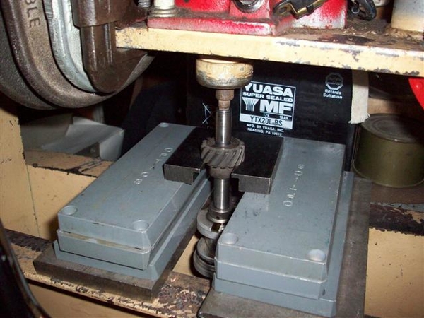
Note that this is the recommended way to remove the gear. Note the little 1/4" stub (in this case one of those little sockets from a multi-bit driver set that I found somewhere....) sticking in the end of the distributor to press against. You can also use a piece of an old distributor drive shaft to either press against or hammer against, but you need to support the gear by the body of the gear and not by the teeth!
Here is the tool and gear: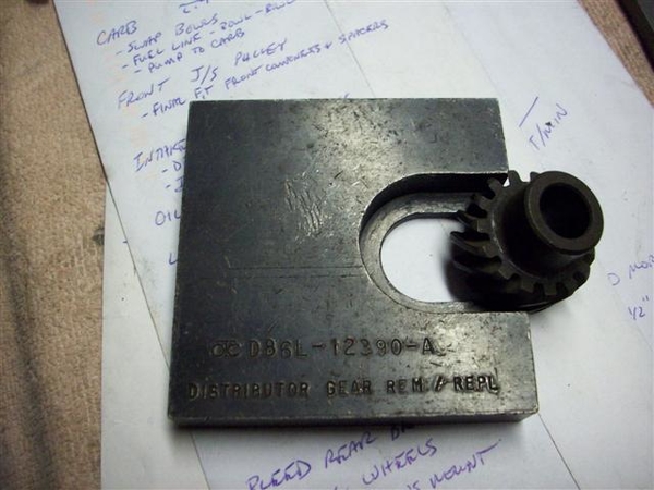
The proper measurement for the distributor is .024" between the little (upper) collar and the body, seen to the left of the gear more "up" on the shaft... Mine was at .025" and I'm not going to redrill a hole for .001"...sorry!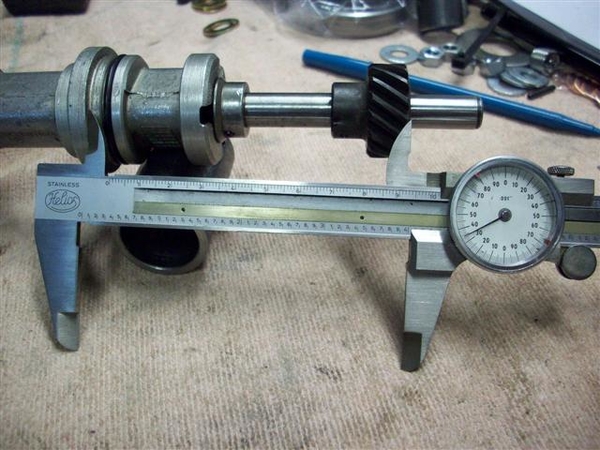
However, the other measurement, from the distributor mounting flange (above the o-ring) to the bottom of the gear, is supposed to be 4.031-4.038" to align properly with the cam gear. I was off by .050" so that was not insignificant...
After polishing the shaft a bit, putting some oil on it, and pushing the gear on in a new spot, it went on nice and easy...but easy in terms of putting it on with a press! It took a few ups and downs....pushing it on...too far...pulling it back off a tad, until I settled on 4.035" or darned close to it!
I then drilled the hole in the gear using measurements and marks I had made and came out dead nuts where I wanted to be. Started with a 3/32" bit and once through one side of the gear, and knowing that the hole was lined up, I carefully used the 1/8" bit to drill the starting side, go thru the shaft, and then drill the other side of the gear. It worked for me, your mileage may vary!
Tapped the roll pin back in place! Bottom is done. Now to the topside!
This distributor was originally for a 1979ish Ford. During these years the 302's were very low compression pigs. As a result, the engineers could get away with running HUGE advance numbers. I found the tower in this one allowed 21 or 16 degrees. It was configured to the 21 degree location... When multiplied by 2 to get crank degrees, that comes out to a whopping 42 degrees of spark advance!
In discussions with the local Mustang shop who are familiar with this engine setup and compression ratio, they recommended 34-36 degrees total advance period, which is pretty much in line what I had been using previously with the Boss 302.
In my pile of parts, I found another DuraSpark tower that had slots of 13/18. I went with the 13, as 13x2=26, plus 8-10 degrees of initial timing would net me 34-36 degrees total advance. If I feel I could use more, I can simply advance the timing up to 12-16 degrees. Keep in mind that the DuraSpark II module has a retard feature during cranking that moves the timing curve back by 10 degrees to make starting easier! I like it!
Here is a shot of the new (old) tower installed and the one I took out is to the right.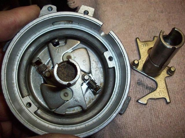
The actual curve would need to be set up on a machine, but from the feel of the spring settings, this should be close! All in (full advance) by 2000-2500 rpm's! A quick check with the timing light will confirm or deny this...
I put all the pickup and stator parts back in the top of the distributor. Checked the pickup with an ohm-meter and found 600ohms. Spec is 400-800ohms for a good pickup module! Cool!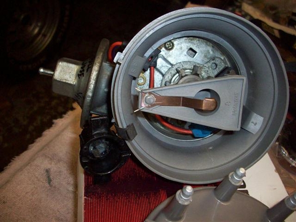
Backed the vacuume advance unit to "loose" but I do not plan on connecting it....at this time.
New rotor, cap adapter, and cap, and we are ready to roll! New wires are still in the box waiting.....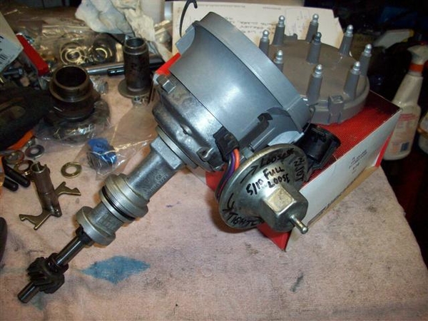
Putzed around with the new bottoming tap I received and finished up the one hole in the rocker arm mounts that I was installing a heli-coil in. This allowed the thread insert to wind further into the hole without drilling a super deep hole into the head.
Fitted one guide plate a little better to the stud and loosely installed the rest of the studs and guide plates.
Adjustment of rockers and guide plates is next, but not tonight!
Ciao!
Steve


Well, back from a great time in Reno! Passed lakes in the mountains still covered with ice!! Not so much ice on the way home though....5 days later!
One lone Mangusta showed up, so needless to say, I checked it out fairly well. Early car, #606, has a very unique "in-dash" AC unit as well as early round top side marker lamps. Was a conversion to an Edelbrock F4B many moons ago....as well as a set of Hall headers and cherry-bomb mufflers. Very sharp looking in red with black interior, took home the "most stock" award I believe. Only real noticeable deviation from stock is a set of aftermarket wheels. (Which the owner would love to replace with a set of stockers!)
Since returning home, not much progress on the Goose. Met with another local Goose owner, who lent me his jackshaft assy and pulleys to check out on my engine. His jackshaft bracket is an early version, with an extra mounting bolt in one of the center positions. If you look at the later ones, you will see a round area just behind the center bearing area where this was...
This version also had all three bearings held in place with snap rings, unlike the later version that I now have, where the front bearing is allowed to float.
I did pick up the new BCA1625 throw out bearing. Mine was new not that many miles ago...but since I'm in here, I'd rather spend the $30 and do it once! The old one can go in the tool box as a spare in case anyone needs one out on the road! I need to install it on the holder/carrier sleeve yet.
Have been a bit busy as I have detoured on a family car project.....getting the old family taxi running again. Blew a head gasket out of the blue....with only about 50-60K on it! (Replacement engine for the car...)
Here's a shot of what I've spent the last weekend and week nights doing!
Our son wants to head down to Monterey this fall to finish his business classes for college, but the idea of taking a pristine 68 XR7 Cougar down there isn't sitting well with him or the previous owner (me!)..... I remember driving a nice 62 Impala SS to college, only to return it home 3 months later due to numerous break-ins and attempts, getting hassled by the cops for out of state plates......not to mention driving it in the salt...!!!
So, the idea is to see if the new head gaskets hold up....and squeeze another 50-60K out of it! Should be ready for the scrapper after that!!! This is a late 97 4.6L SOHC engine that will go back into our 92 Touring Edition Crown Vic. Cleaned up all the surfaces, checked the #8 rod bearing for wear, found little to none, so it's getting 5 qts of fresh oil, a new filter for a few hundred miles, then another new filter and 1 qt of oil and it should be good to go!!! This picture was early last night, but later it had the front timing chain cover, oil pan, and valve covers on it. Tonight it got exhaust manifolds, intake manifold and most of the wiring. I don't have a metric 12mm harmonic balancer installer, so ordered up a special long bolt from Fastenal today and will turn it into an installer.....! But will need to finish that in the car as fully threaded bolts are not in stock anywhere around here! I believe it is coming from IL.... BUT, the important thing is that I can drop the motor in one of these evenings and then spend the weekend buttoning every thing up and plugging all of the wiring back in! Then one more project will be off my list, and back to the Goose!!!!!
OK, now for some GREAT news! While in Reno, I happened to ask Steve Wilkinson if he had any Mangusta front jackshaft pulleys.....he replied that he thought he had two of them! Called him up last Tues or Wed, and sure enough, he had two on the shelf! One had some brazing on the backside....and one looked like new... "I'll take the latter please...!"
Here is what showed up today!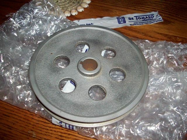
It fits my shaft just fine, but I still need to deal with getting the bearings to fit a little better!!! A couple hours on a lathe and I should be good to go....make a few spacers and then start torquing down an intake manifold!!!
I think after that, it is carb and fuel line work to do, fab up some sort of throttle cable bracket, and then work on dropping the engine back into the car!!!!! WHOO HOOO!!!!
Steve


quote:one looked like new... "I'll take the latter please...!"

")