Mark,
Your puzzle point is well taken! Very much to the point in my progress or lack of lately!
Spent last weekend up in Gold Country near the small town of Plymouth. Attended a flea market where I picked up some tool widgit items, a wine festival with local wineries and restaurants doling out samples, and a small car show of perhaps 18 cars and trucks. Some really nice examples! My fav was a 1954-56 customized Merc. Sort of a seafoam metallic green with faded in highlights etc. Have pics to post later....
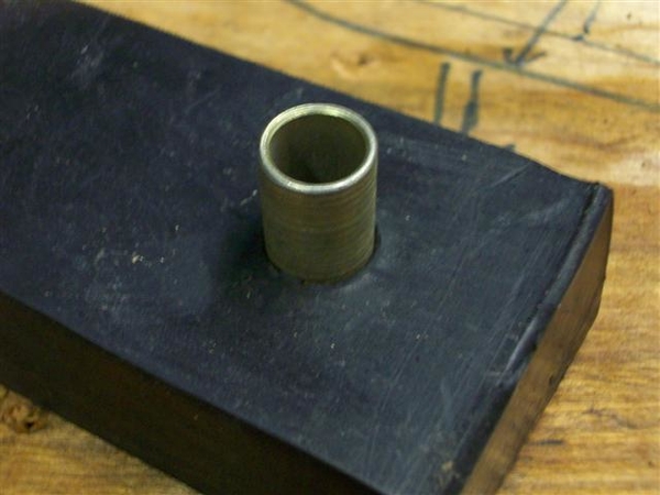
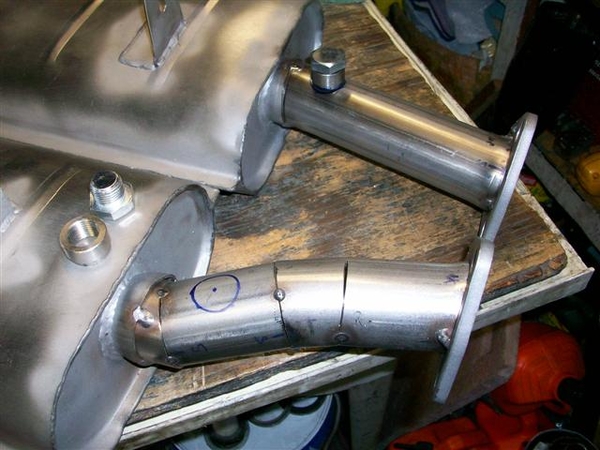
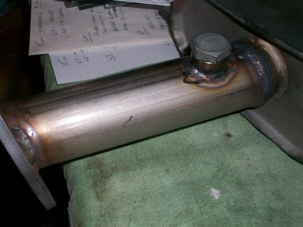
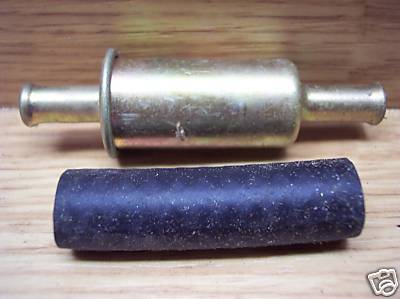
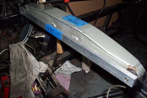
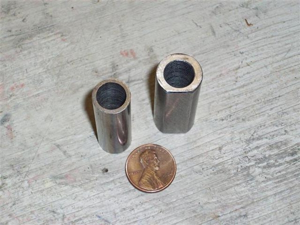
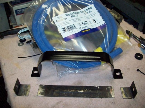
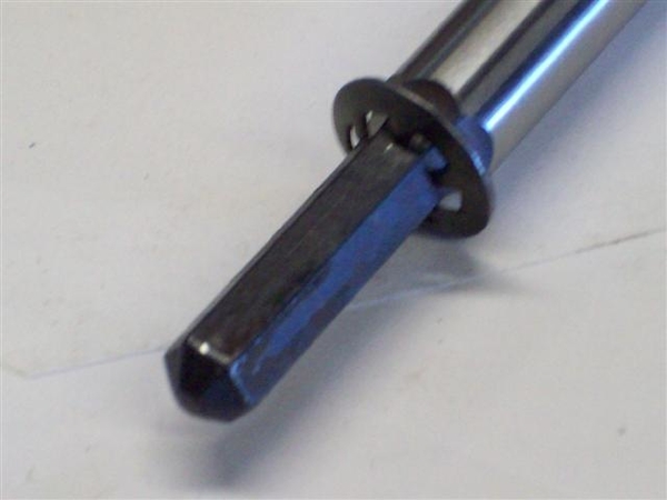
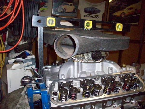
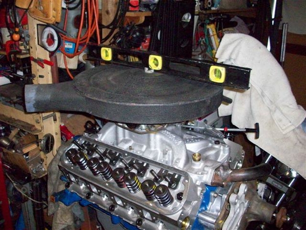
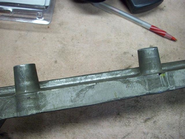
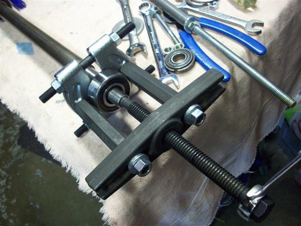
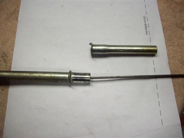
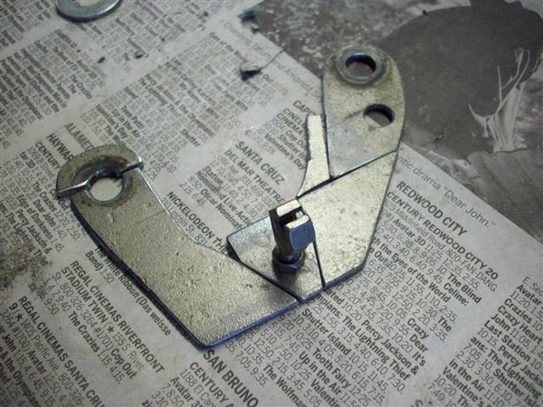
Before we left on Friday, I dropped by the neighborhood machinist's house and milled down a piece of aluminum that I will have welded onto the rear of the intake manifold, to act as the rear jackshaft support, as was on the original cast iron intake. It will serve to give the bracket some rotational strength. I also cut up a piece of black iron pipe (removed the threaded section) to form the basis of a tool for pushing or tapping bearings onto the shaft.
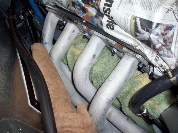
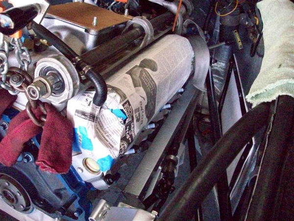
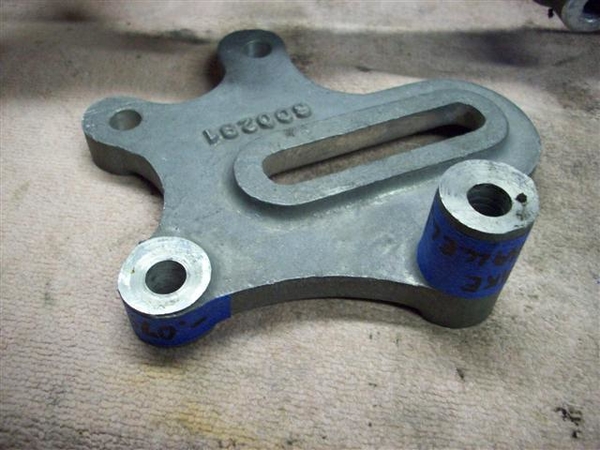
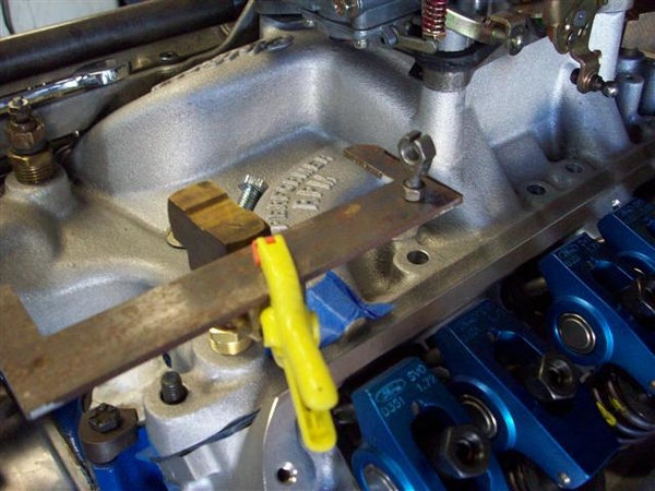
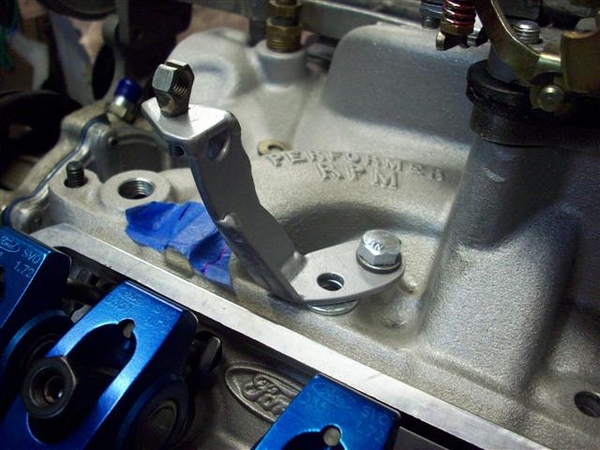
Monday night I spent hand filing and fitting this piece of aluminum to the back of the intake. Once I got that all squared away, I decided it was time to weld up the adjustable guide plates.... Tack welded them. Covered the valve springs and everything else with aluminum foil. It forms nicely around stuff and won't burn...and you can flatten it out and do it again! This went well! ...or so I thought....
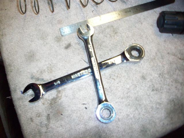
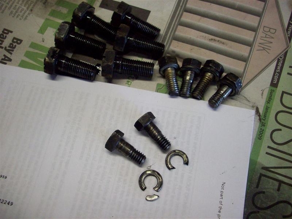
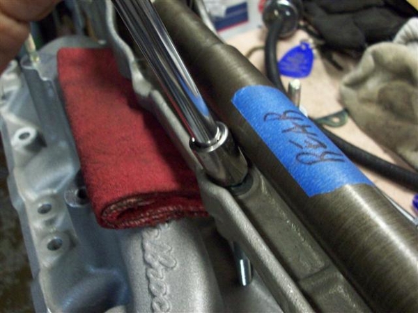
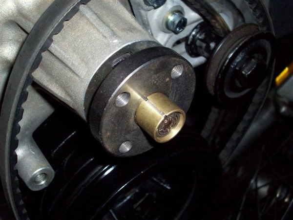
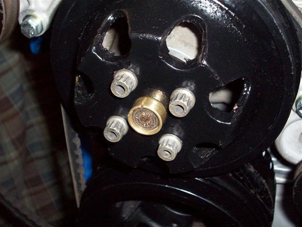
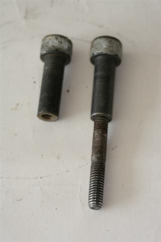
Tuesday: During the day, visited the local "nut-n-bolt house" (Olanders) and picked up a set of 5/16"-18x3.5" socket head cap screws in stainless to use on the 4 bolts of the jackshaft. Pricey little buggers! Five of them ate up a $20 bill.... (need to get the socketed allen bit for these now too! 3/8" drive should be good.)
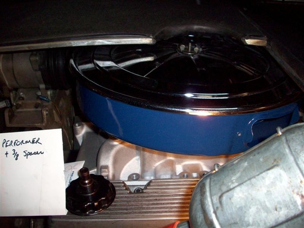
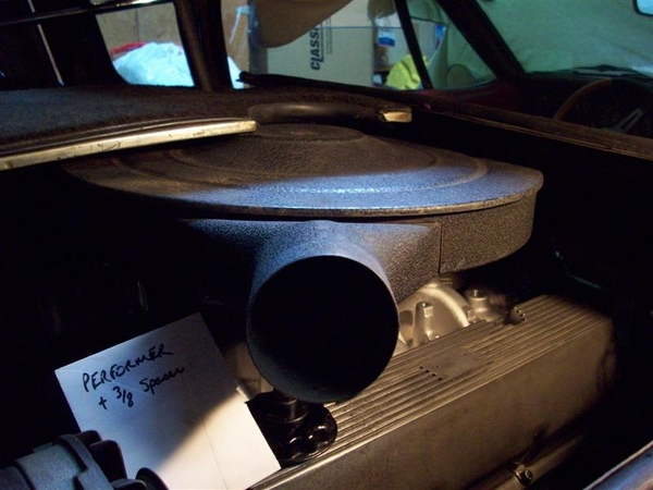
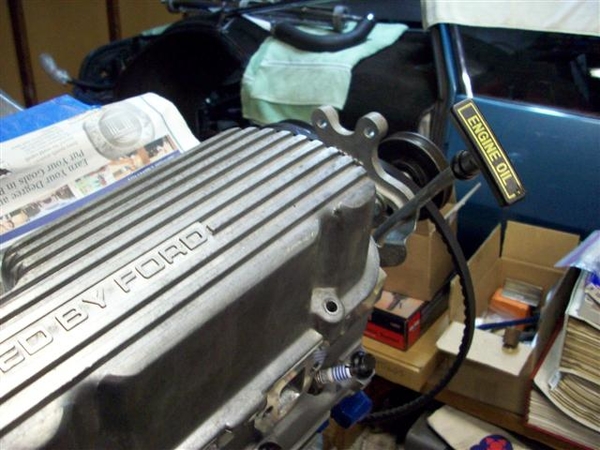
Also ordered a new set of valve covers from Rousch. They are Ford Motorsports covers, but Jack has the best price in town! $129 for a polished set! They will clear the rocker arm nuts with room to spare, and will have the old look of the Boss 302 covers. Finned on the top.... Would have loved to use my aluminum "Powered by Ford" covers, but they are just too low, and spacers cost almost as much as a new set of covers....so....it was really simple. M-6582-BOSSP is the part number.
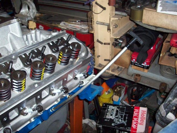
Next....torque down the rocker arm studs and see where the adjustment is.....after the welding. Things start taking a turn for the not so good here.....
When mixing and matching parts, materials, and manufacturers, not to mention blazing a trail in engineering combo's of parts, Mr Murphy is bound to appear. He did. In oh so many ways....
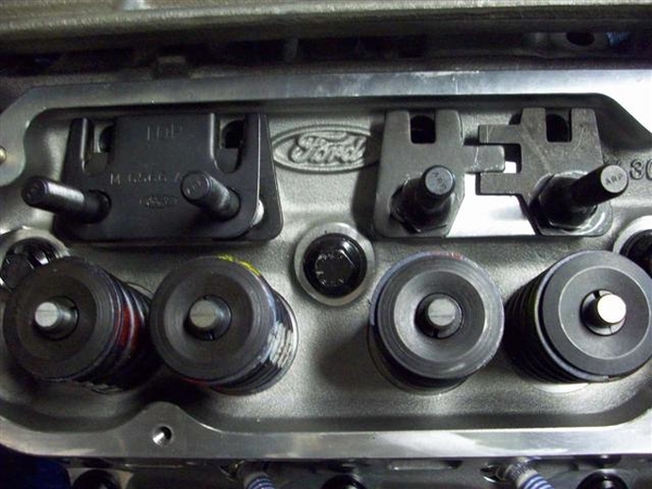
When torquing down the rocker arm studs, I used a torque spec from an old Ford shop manual for removable studs..... Later I found out that I should have reduced that amount by a lot.... On one of the rocker studs, I believe the guy that machined my heads may have not taken out enough material and I believe I was bottoming the stud out....as it felt like I was moving aluminum instead of making things tight..... These instructions were later found in the rocker arm info!! Go figure..... I guess I should have "read all the instructions before beginning!"
You know you are in trouble when the torque wrench doesn't click...and it doesn't seem to get tighter.....and then your brain finally says STOP! (before you really screw it up!) Well, I think I screwed up....literally!
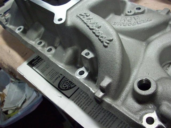
I gave up and started looking online for torque specs. I got nothing with the ARP studs. Their website does not distinguish torque specs between ferrous metals and aluminum......no help! Edelbrock says 50ft-lbs, but they cheat and use steel threaded inserts in their heads! (NICE!!!) After looking long and hard, a 40-50ft-lb figure appears to be in order. There is no mention of this in the Ford documentation because the heads were not designed for this type of rocker mounting! Gloom on me! (They DO mention the intake manifold torque specs....thank goodness for that! Although it really isn't all that different than the specs for the cast iron manifold!)
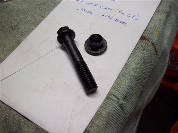
The studs I am using have a .710" portion to go down into the head. The top .125 of it is tapered and not threaded, to accommodate an 1/8" guide plate like I am using. When the heads were cut drilled and tapped, the machinist perhaps mistakenly countersunk the holes to allow for this upper tapered portion, not realizing that the guide plates covered this portion and that the holes could be made with very little countersink at the top! (I thought I took him in everything.... been too long, CRS...!)
With only about .575" of threaded stud going into a hole that is now shy another .125" of threads at the top of the hole, I'm getting very close to "engaged threads= 1x diameter" of fastener. Normally I think the spec is closer to 2X the diameter to get proper ratings......advertised for the fastener.....
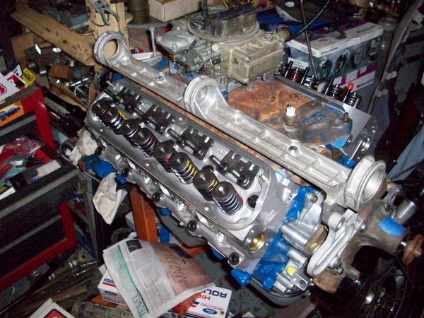
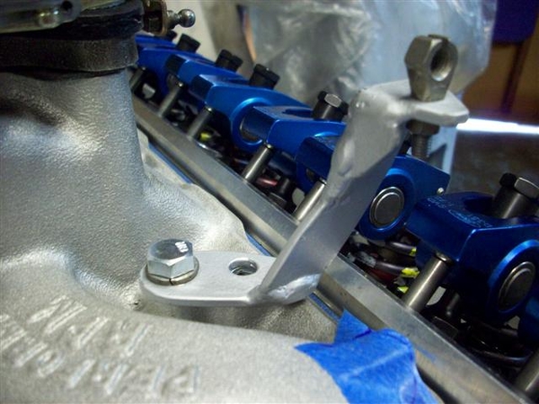
Anyway, all of this turns out to be correctable and also a moot point. In the process of welding, the guide plates all shifted due to expansion/cooling...when I checked, all of them had splayed the rockers out off of the stems! (whatever is the opposite of pigeon toed...) I should have probably torqued the guide plates down first, then tack welded....
Thankfully I only tack welded them and was able to bust them loose again after a few seconds with a die grinder. Will need to set them all up again, and number the rocker arms to make certain there are no issues due to manufacturing variances, and then tack them again!
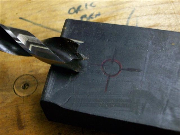
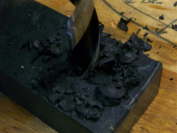
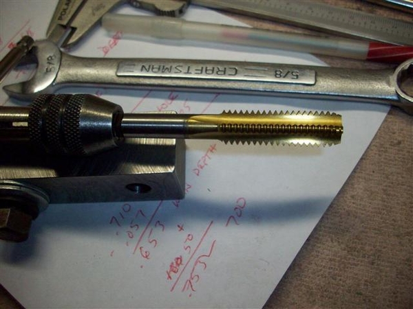
If this doesn't work, I will have to check out the tin Ford Motorsports version that I purchased initially, but rejected due to reports of them breaking..... If I go this route I will need to drill the holes deeper and tap them with a bottoming tap. Searched around the internet for a thread repair kit and taps....
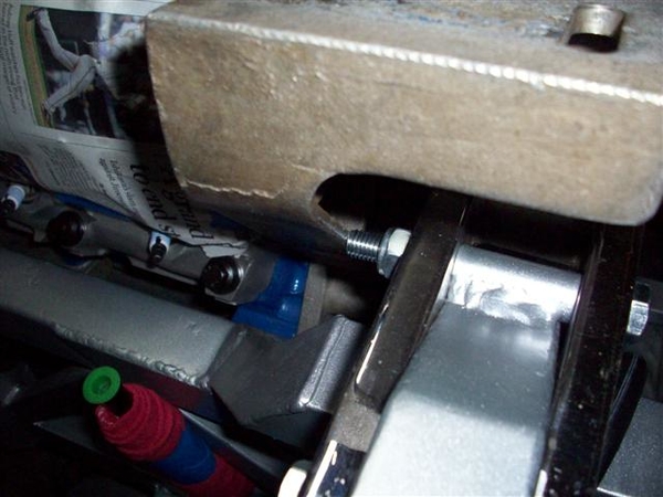
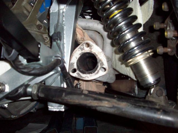
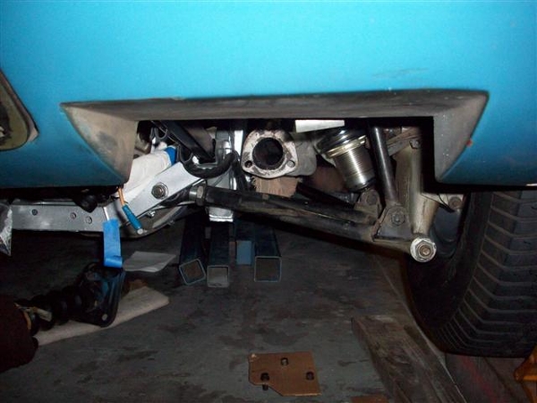
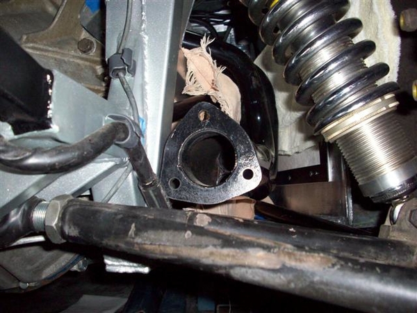
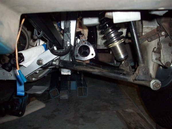
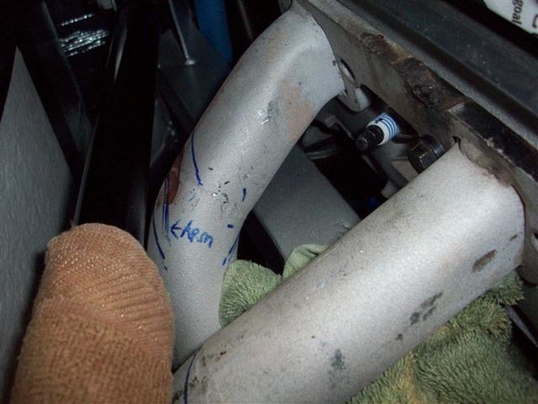
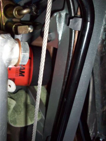
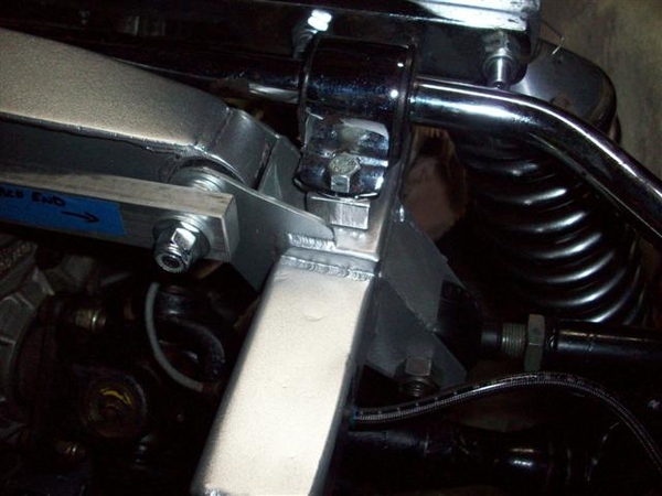
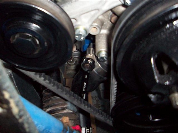
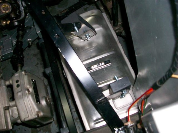
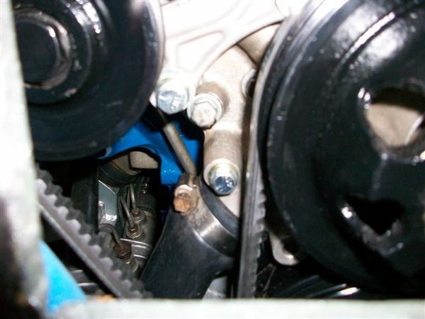
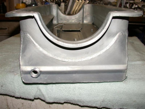
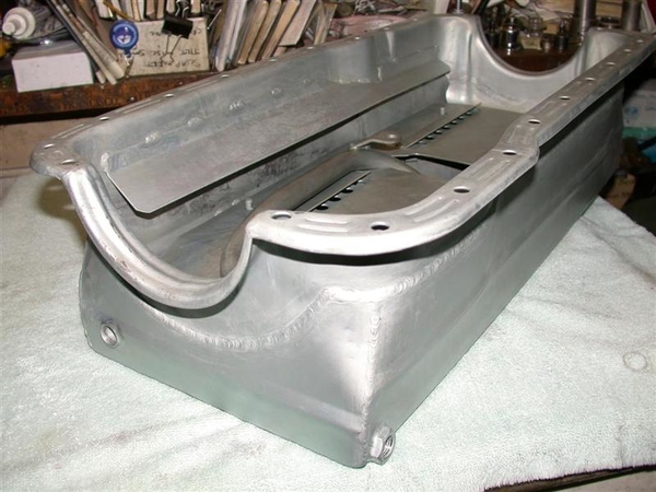
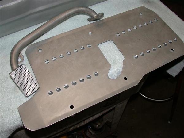
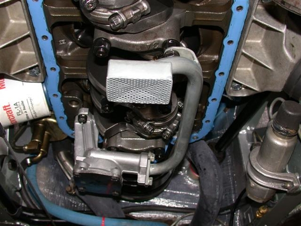
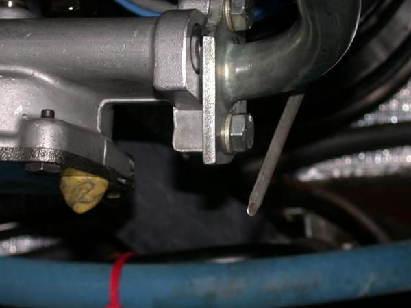
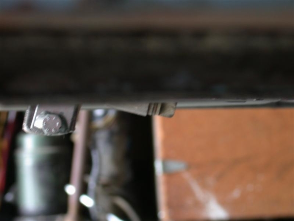
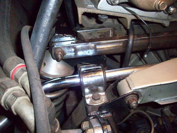
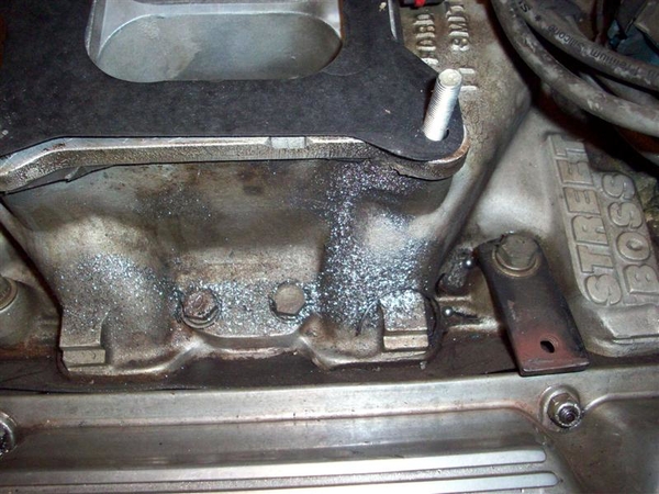
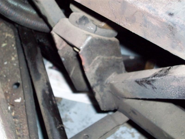
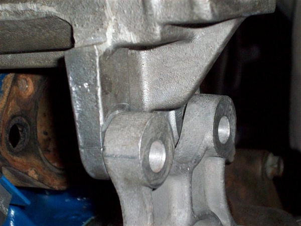
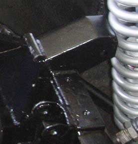
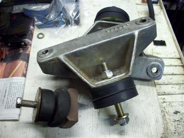
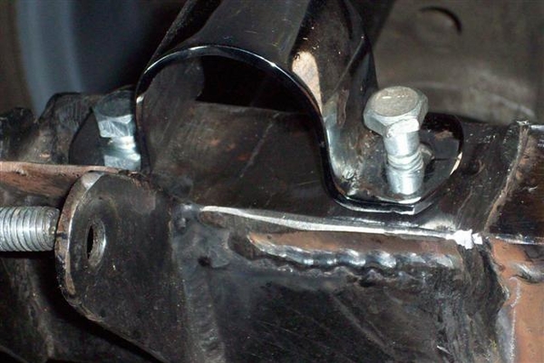
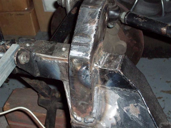
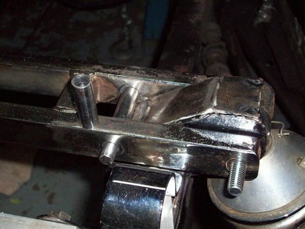
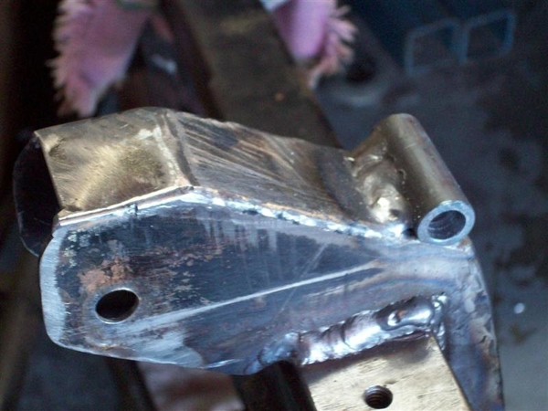
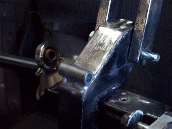
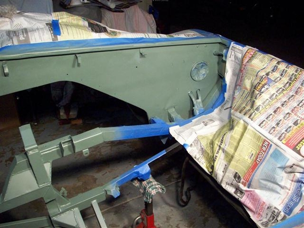
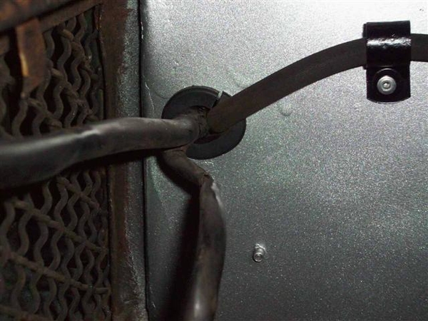
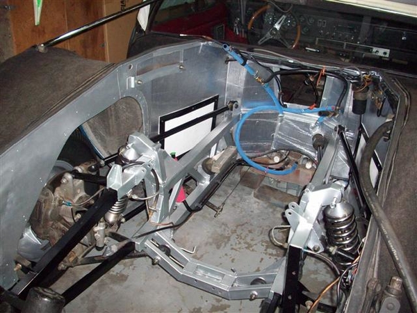
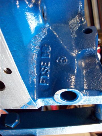
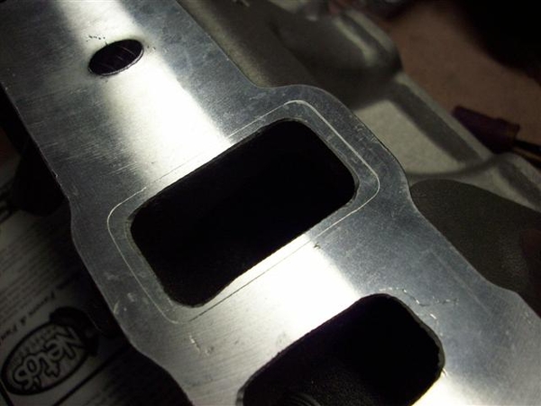
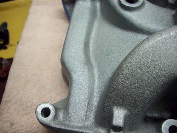
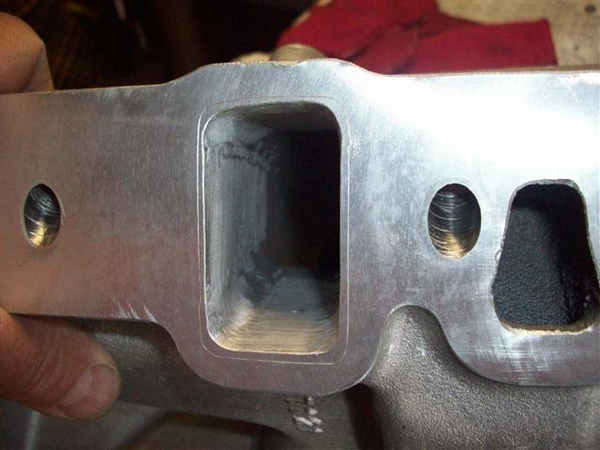
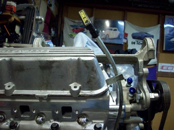
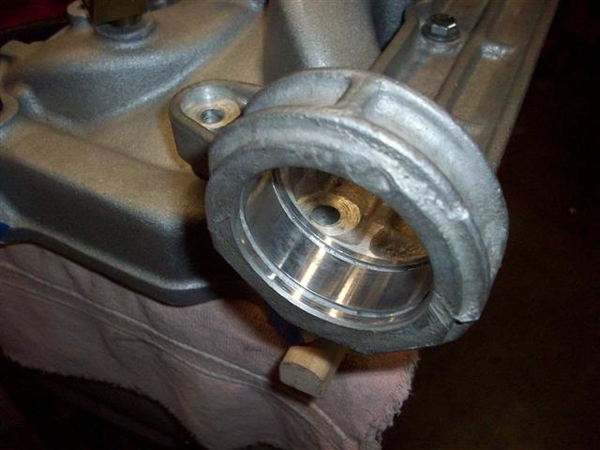
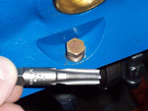
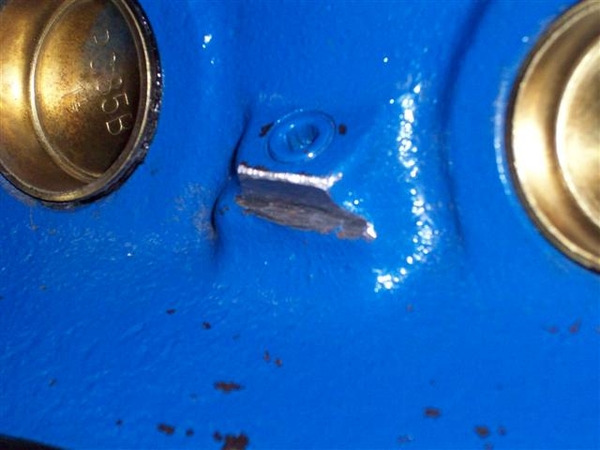
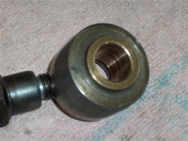
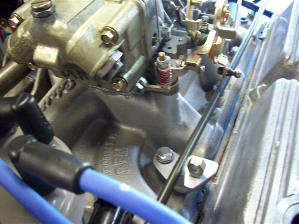
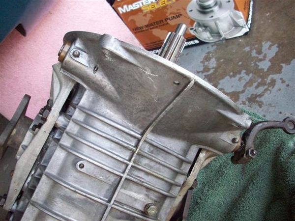
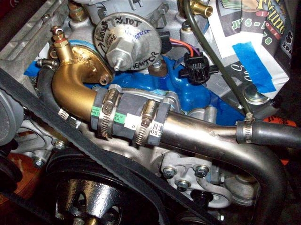
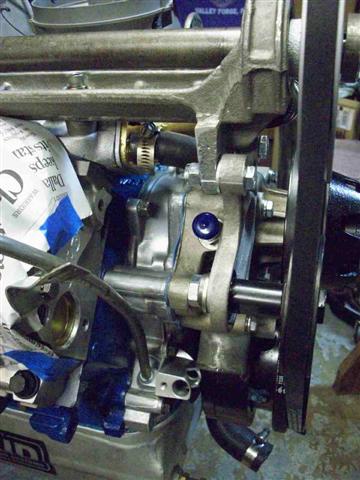
The one thing I did do that wasn't messed up, was modify the drain boss to clear the motor mount bracket on the LH side of the engine block, as seen above in one of the shots on the top of page 10 I believe. Just needed to take a tiny amount of metal off for clearance. Smoothed it up and took off the sharp edges with a file. Add paint later.....
Wednesday: Ordered a heli-coil kit with .656" deep inserts. Should work fine for me. Will hopefully order the bottoming tap Thurs. and get that moving this way. No need to have this stuff immediately, as I am out of town working from Friday until next Tuesday when I go to work one day here, then go back down to LA for two more long days!!! No Goose time!
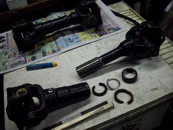
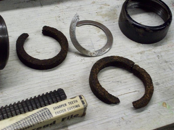
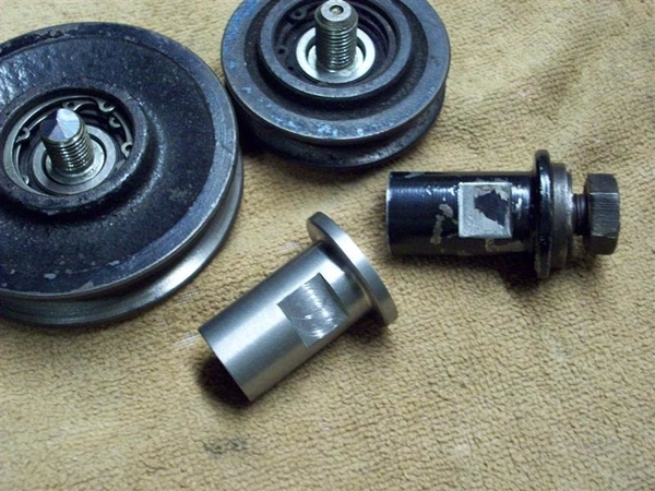
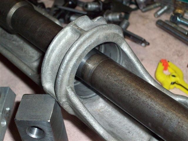
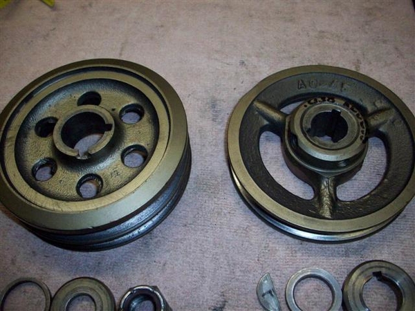
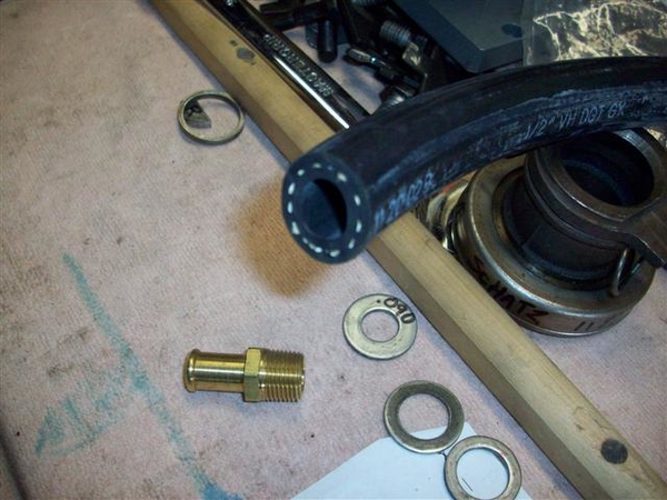
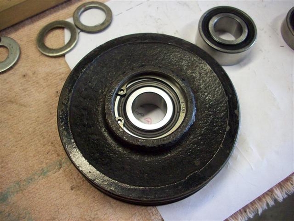
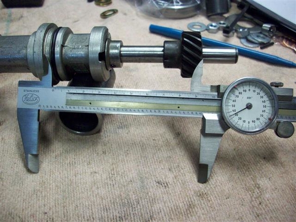
I also called the bearing house in Gilroy that I ordered my new jackshaft bearings from, to check on getting snap-rings for the new 52mm bearing, and found that they had them in stock! (.076" thick for an ID hole vs outside) I had stopped by my local Motion Industries on the way to work this morning, but they didn't have anything in stock and suggested that if I did order them, I'd be taking possession of a whole crap load of them!
I wasn't certain of the thickness of the snap rings when I was at work calling (didn't have a micrometer handy....) so will call Girardi back Thurs and get those moving this direction too!
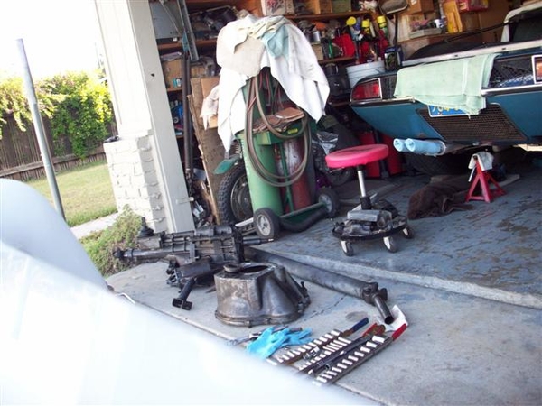
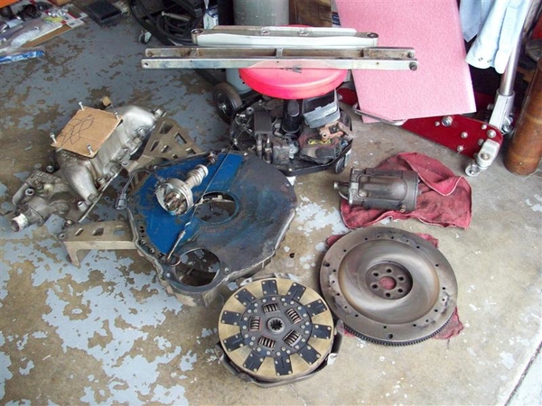
Tonight I worked on getting the oil pan off of the old motor. I still had a long block out back in the shed, sitting on the bottom of an old shopping cart. It works well for a small block... My plan was to yank the heads which would allow my son and I to lift the remaining short block up onto an engine stand from where I could then remove the pan. Well, easier typed than done!
When I built this motor back in '01, I used head studs and the special spacers to adapt from 1/2" holes in the head, to 7/16" bolt size of the block. I loosened up the rocker arms, removed some for access to the head nuts, and took them all off.....but due to the studs, which sorta point all over the place, they don't just fall off like you would get once you pull all the bolts out.... All I can say, is that I didn't have any head gasket issues!!!! Eventually, with enough prying and grunting, and more prying and eventually loosening up the little spacers, I was able to get most of those spacers out....which then made it a micron easier to lift the heads up and off....but it took a LOT of prying and convincing....certainly not as sexy as when the guys do it on a top fuel motor!!!!

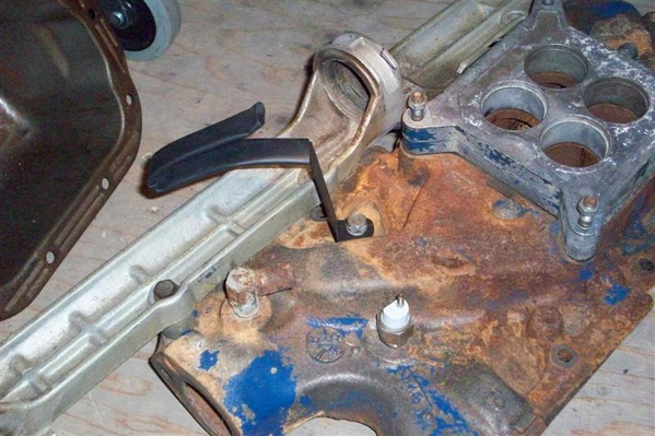
Eventually got both heads off (in the dark no less), short block up on a stand, fluids drained more final like, and the oil pan removed. Wiped down all the bores real good and generally cleaned it up a tad for storage, then bagged it and put it back in the shed!
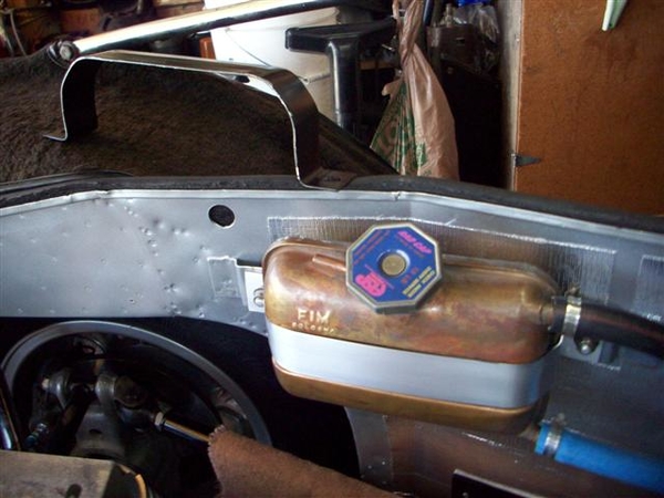
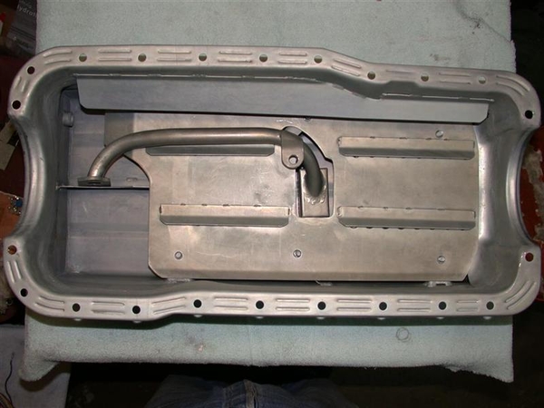
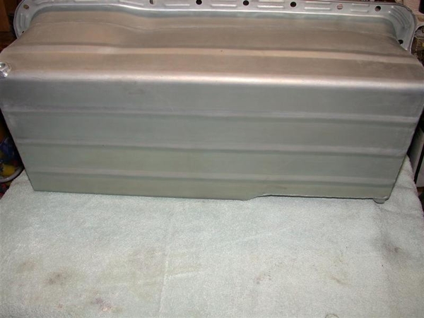
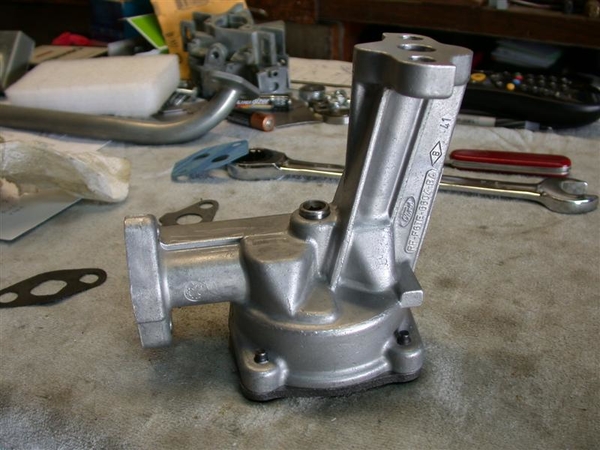
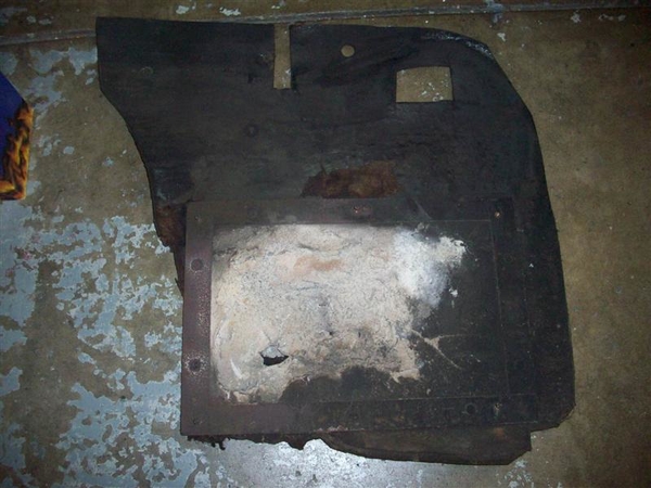
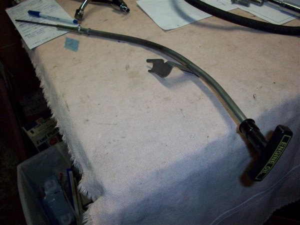
Cleaned the oil pan up in my solvent tub and stood it up to dry. It appears to not have the provision for a LH dipstick mount...... Sorta rules that out......but I wasn't too wild about a LH version anyway.. It is a shame that this oil pan may now be too deep for the car!!! (Now that the chassis engine mounts are lowered back to stock!!!) Oh well, it's just money..... Maybe I can sell it to a GT40 guy!
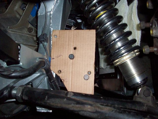
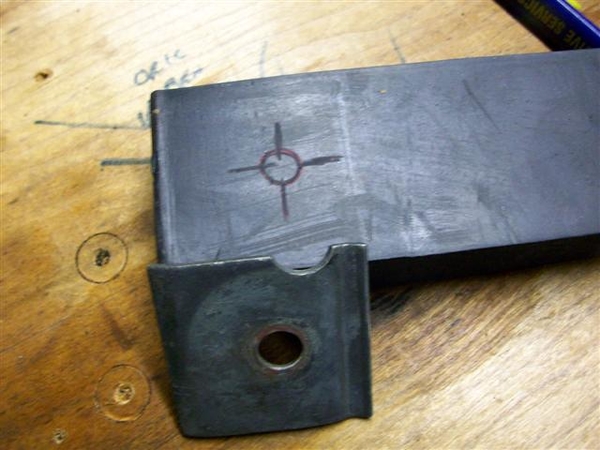
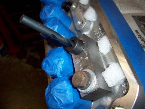
What I will do now, is design a drill guide that I can bolt down to one of the rocker holes to guide me when drilling the other side! If the heads were off, I'd be doing this differently.....but I have a $75 set of head gaskets in there that I truly do not want to waste! Just take my time, cover everything with masking tape and tin foil, and I'll win! I'll send this design off to my dad who can machine it up and mail it back to me in time to put it to use on Friday I hope!
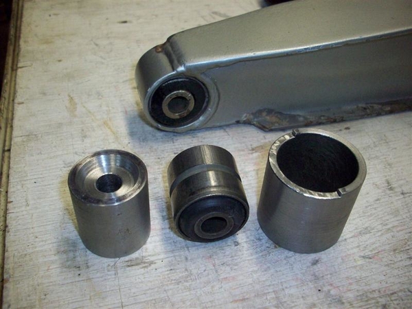
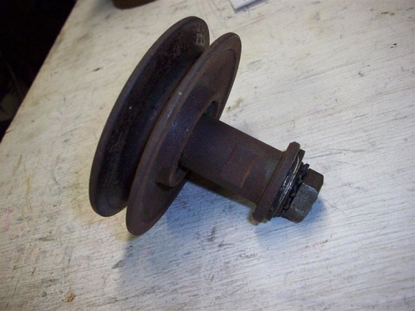
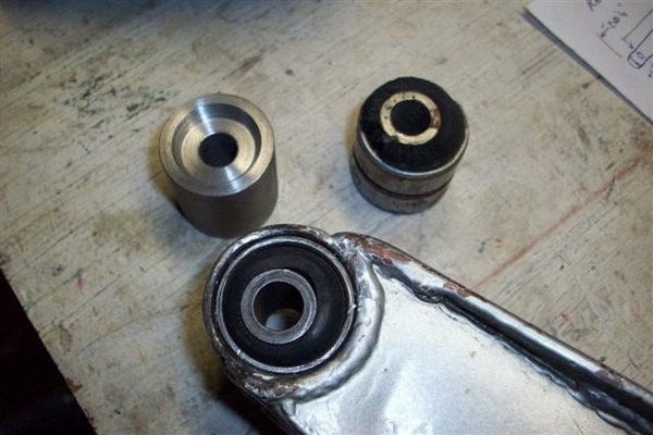
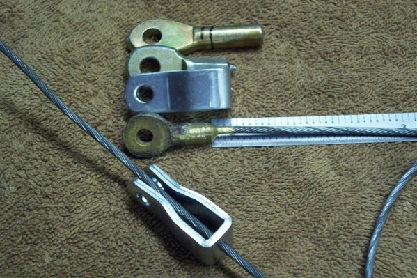
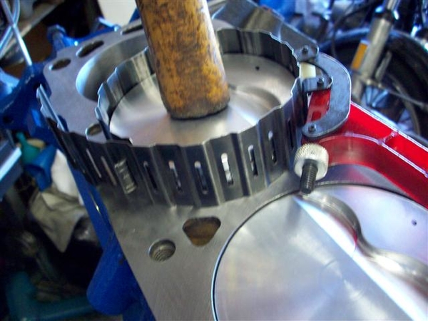
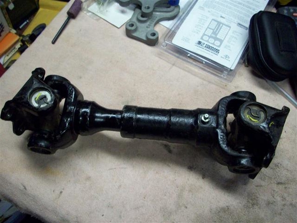
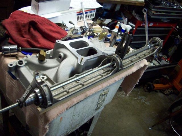
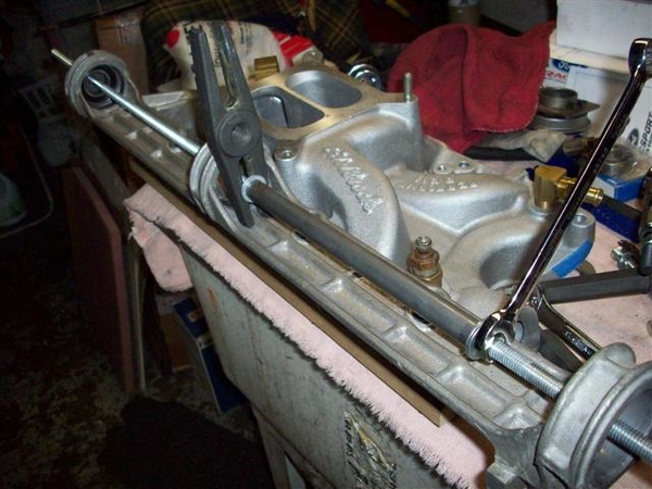
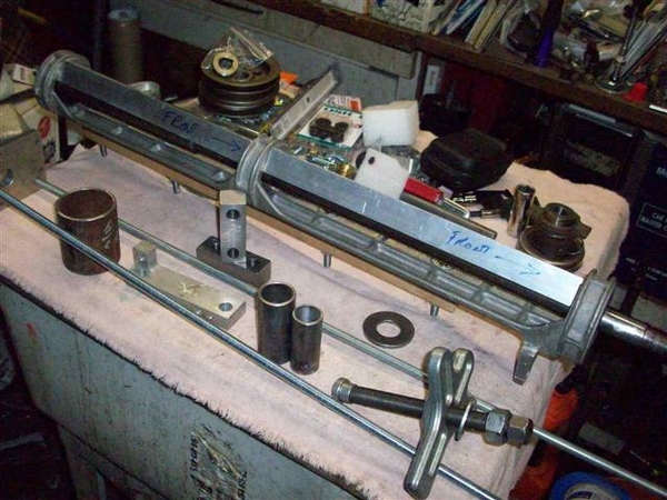
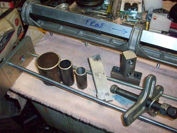
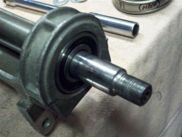
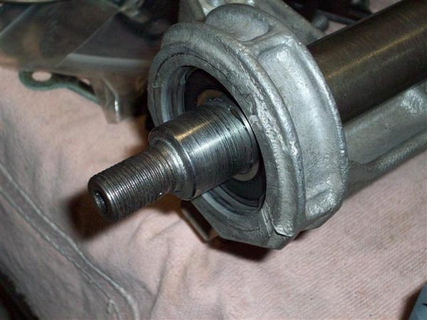
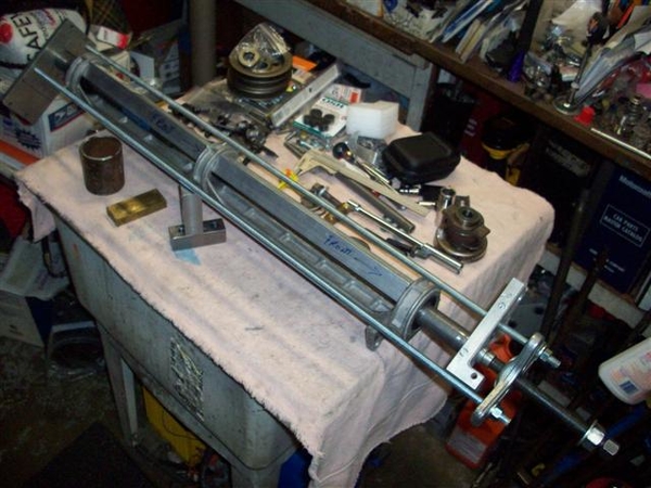
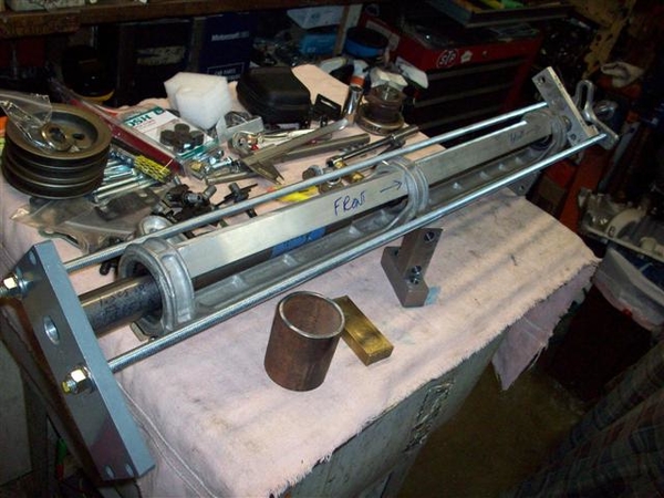
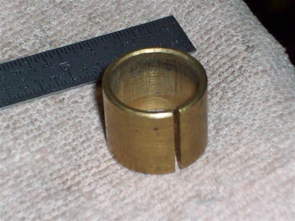
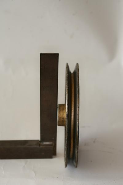
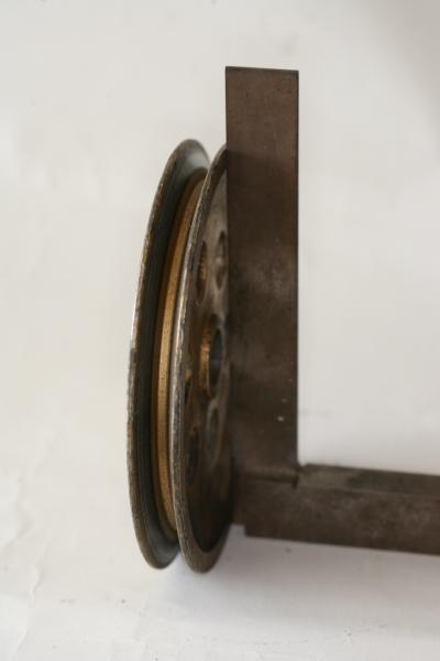
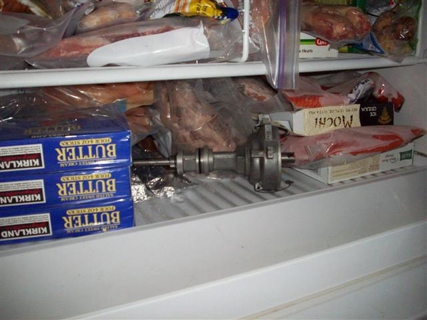
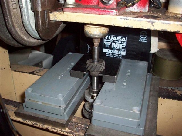
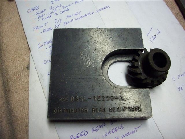
I am also working on thinking up a set of pieces that I can use to push and pull the jackshaft in and out of the carrier bracket, as well as putting bearings on and pulling them off of the shaft.... I have some good ideas, but need to do some more machining and cutting of some 1/2" aluminum stock that I have! Not to mention visit Home Depot's metal section to see what I can find for suitable materials that won't weigh a lot yet will be strong under compression.....
OK, that pretty much sums up this week. Perhaps tomorrow I can post some pictures, as I won't be doing too much else, except for packing my bags to travel!
Ciao!
Steve


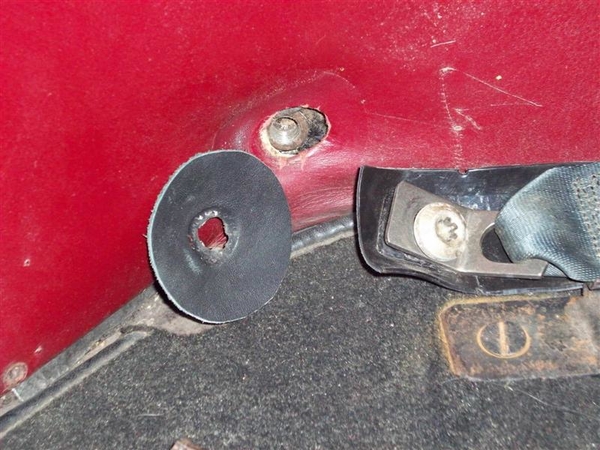
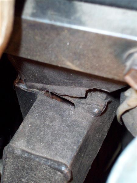
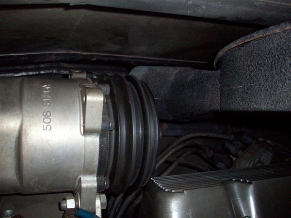
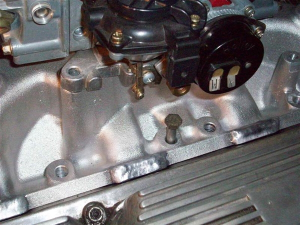


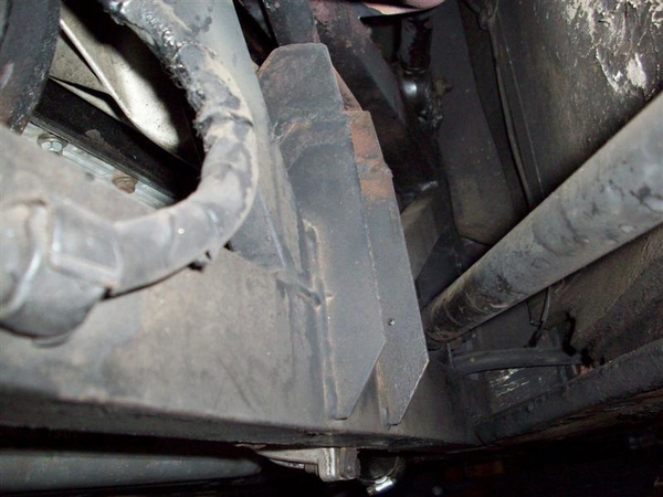
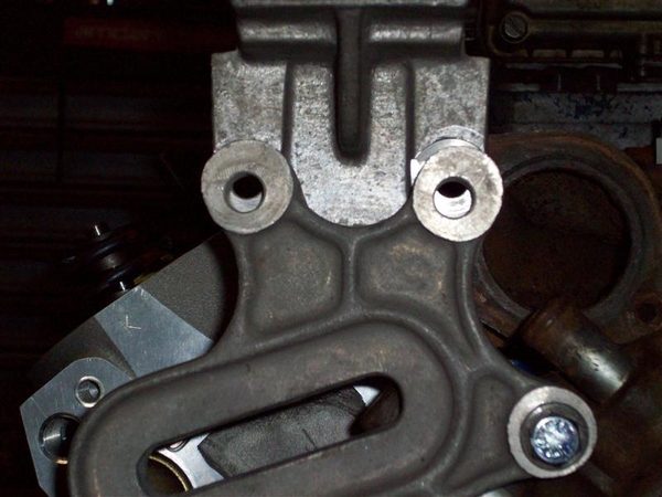


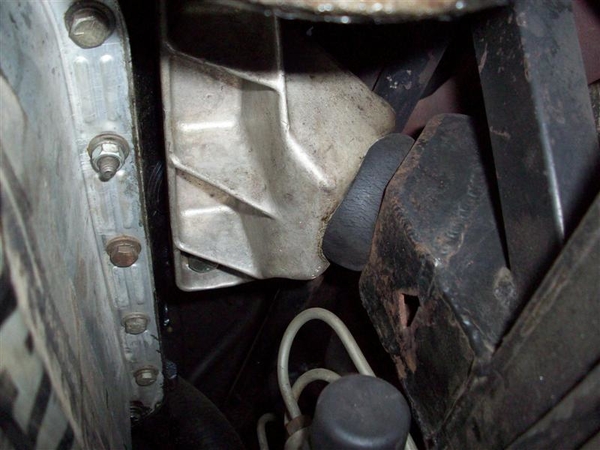


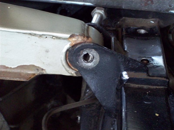


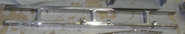


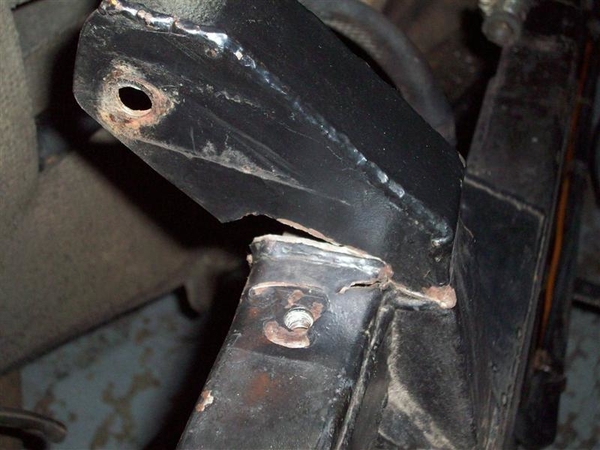
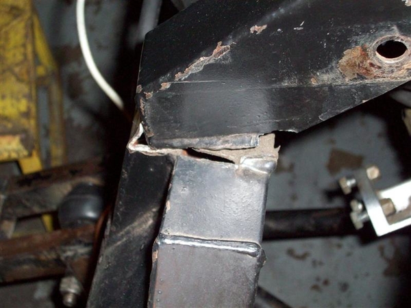


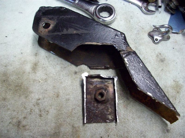


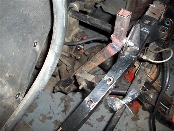


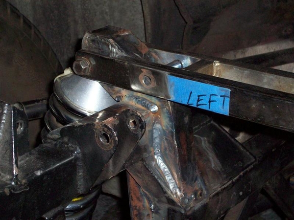
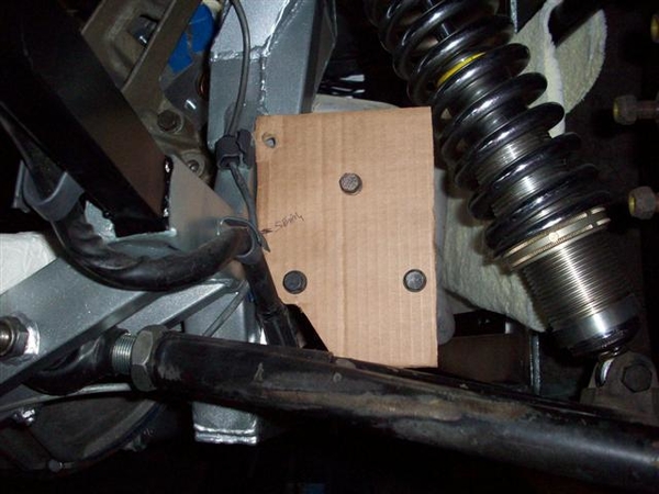
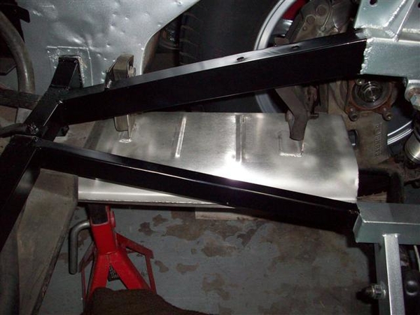
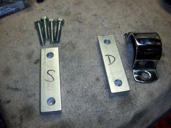
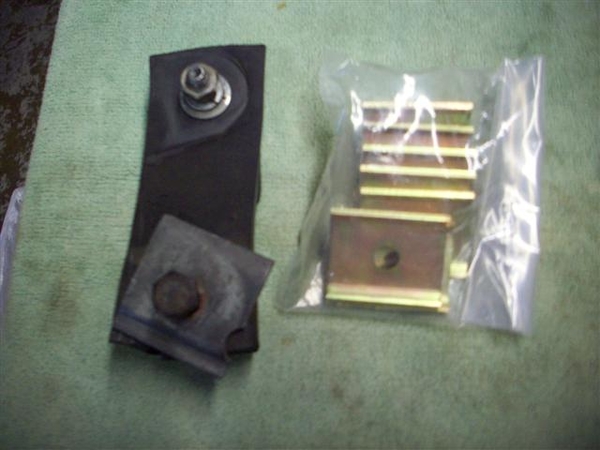
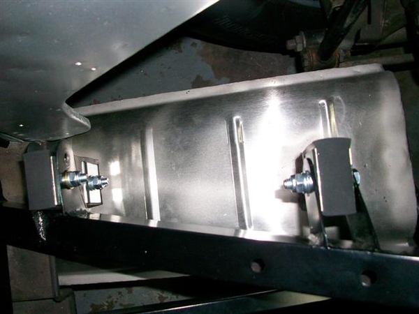
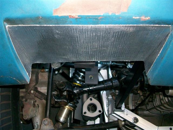
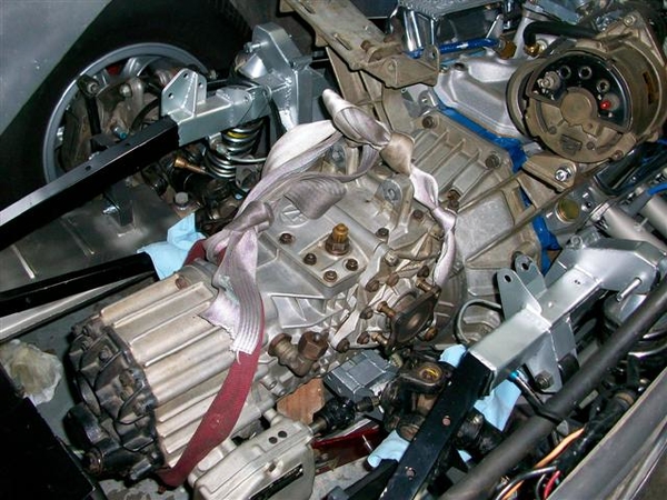
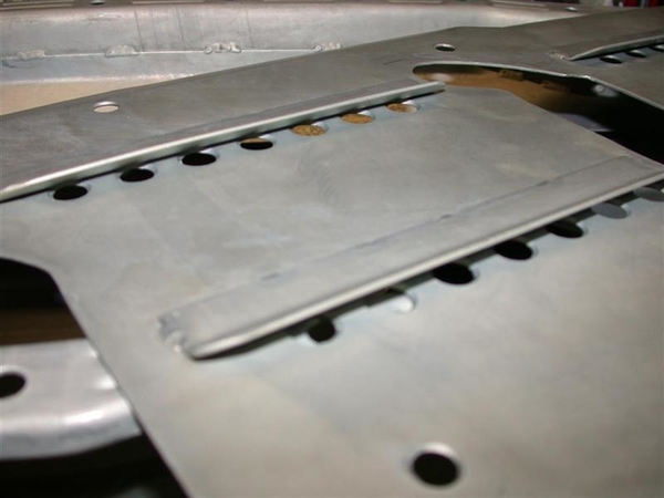
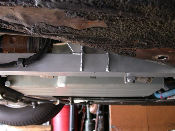
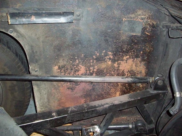
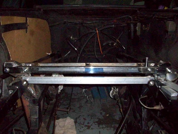
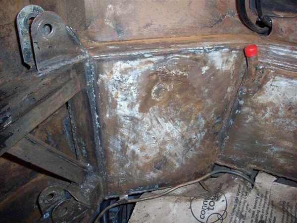
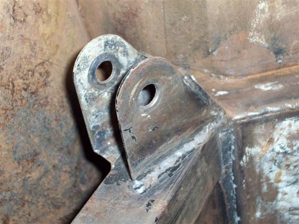
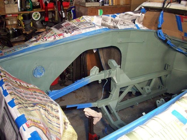
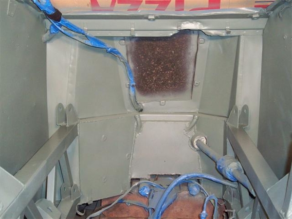
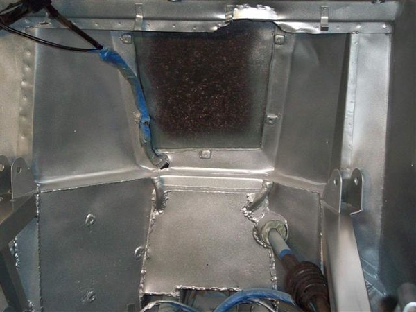
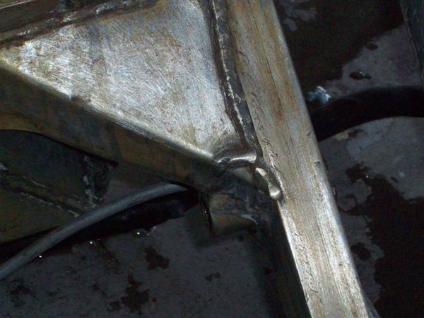
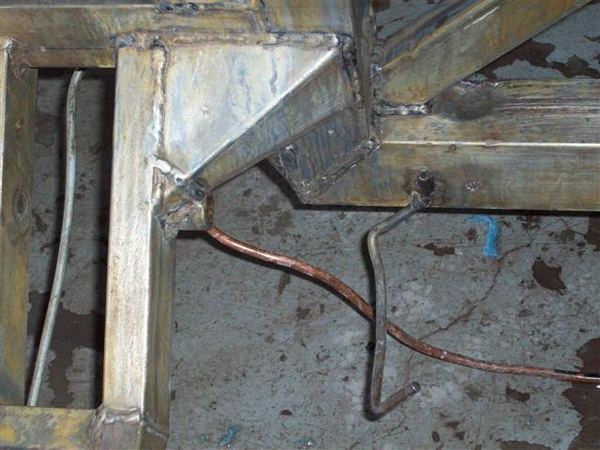
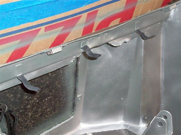
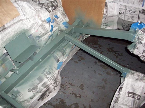
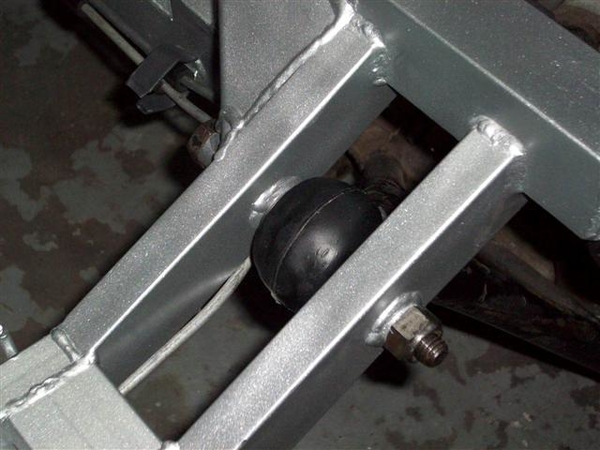
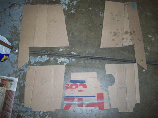
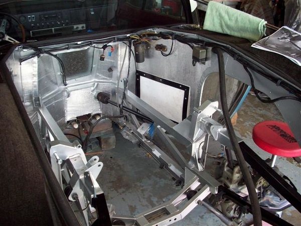
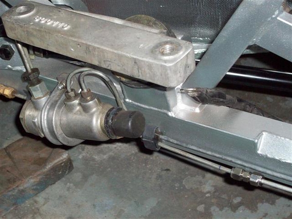
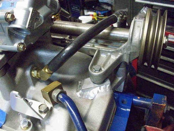
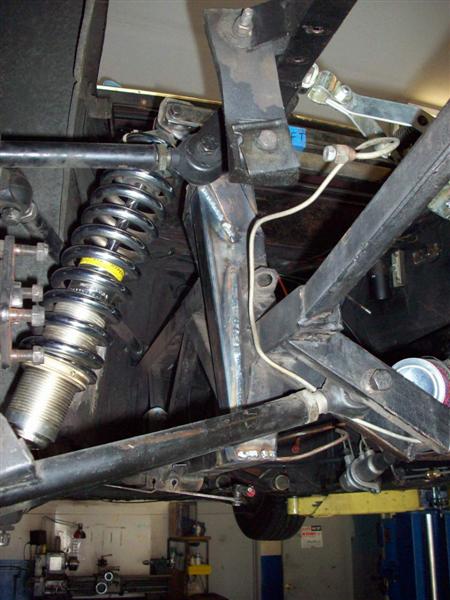 This mirrors what the factory originally did on the RH side to make up for the notch in the frame to accommodate the shifter linkage.
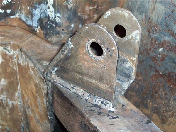
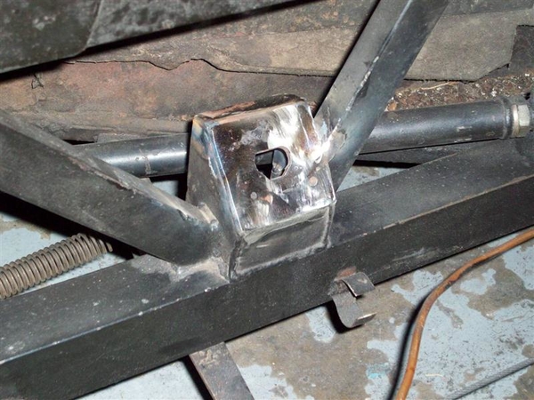


")


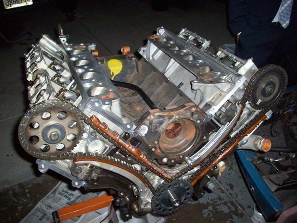


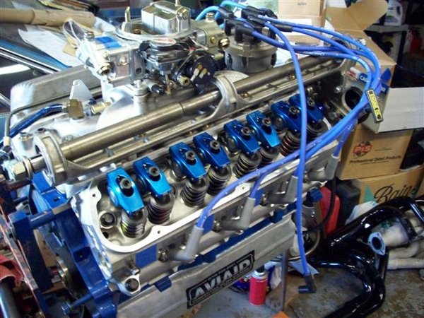


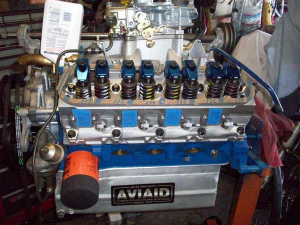


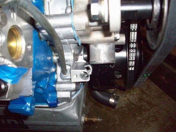


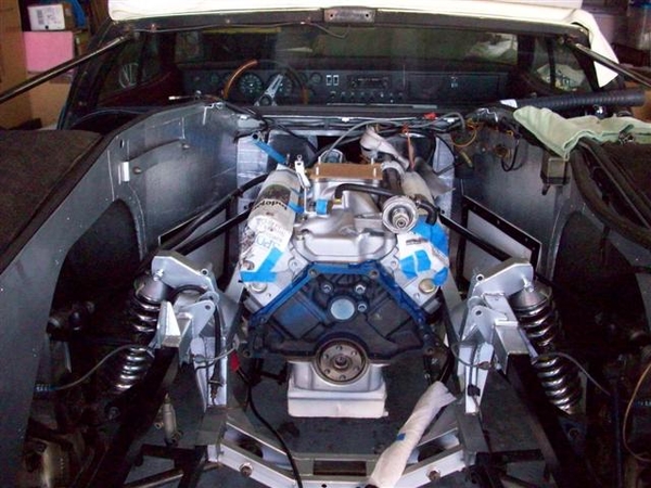


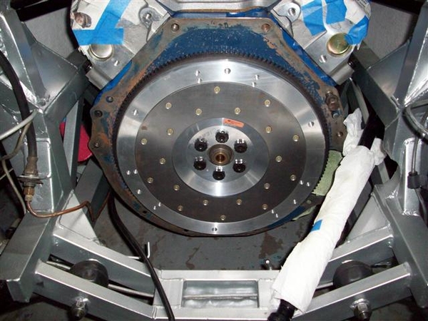
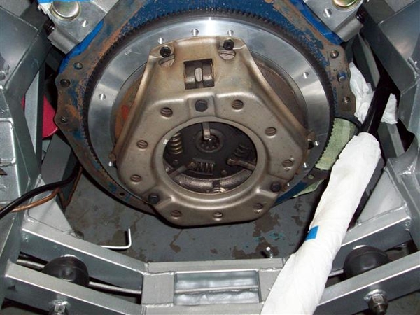
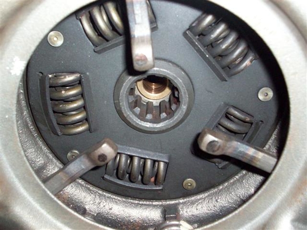
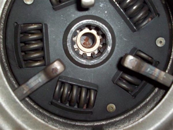
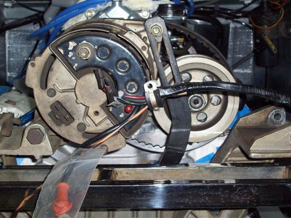
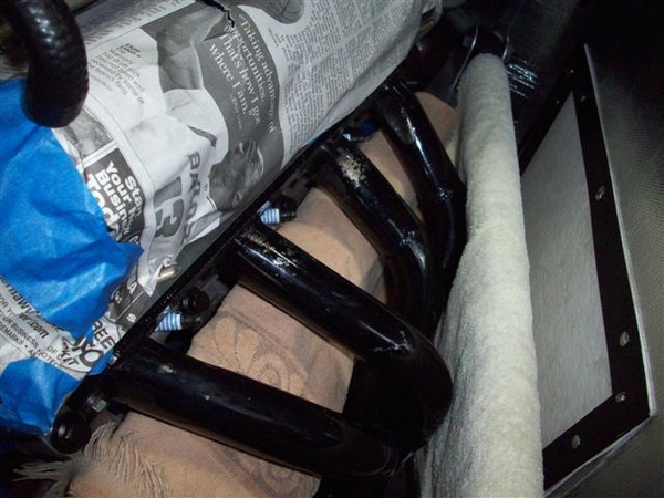
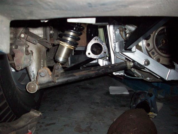
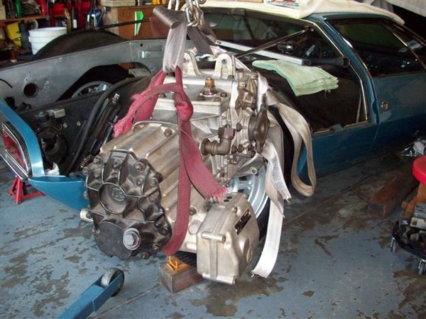
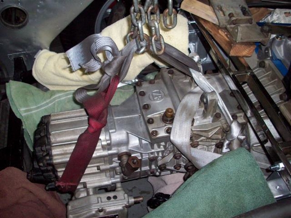
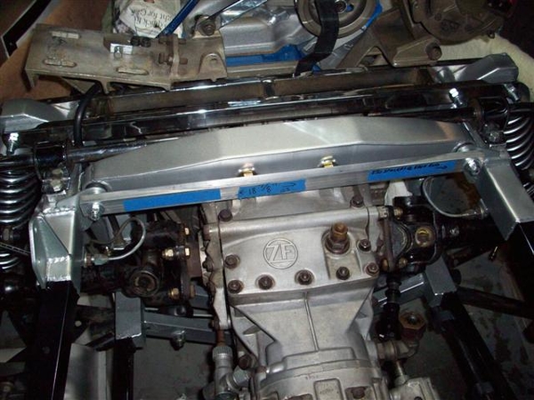
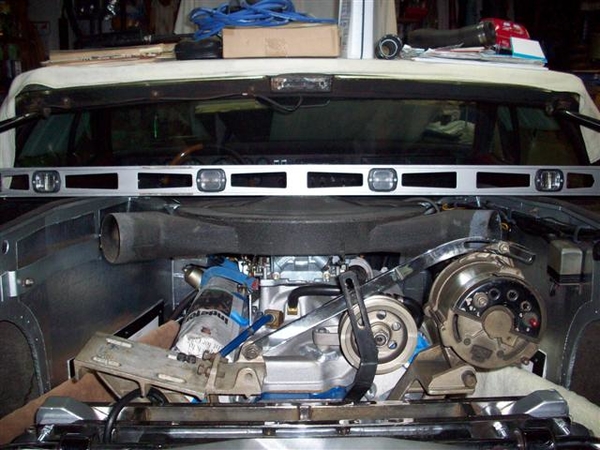
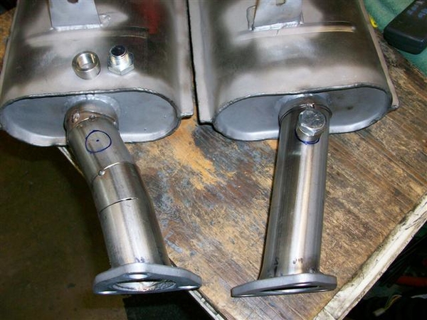
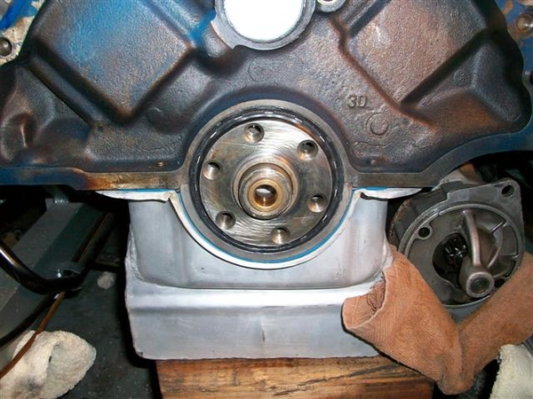
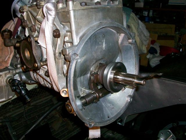
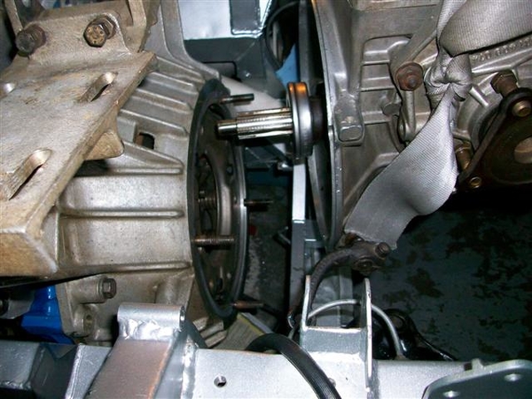
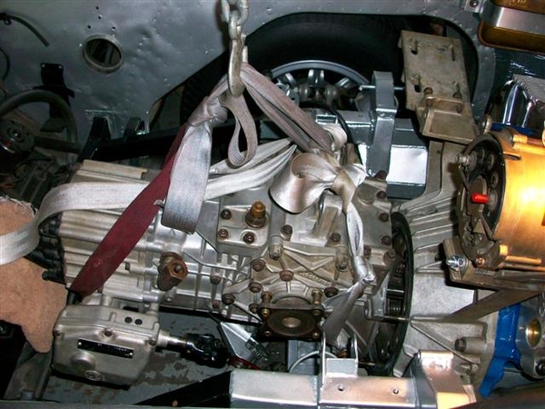
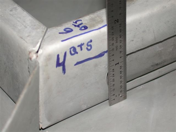
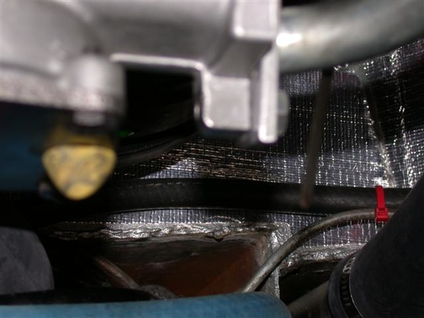
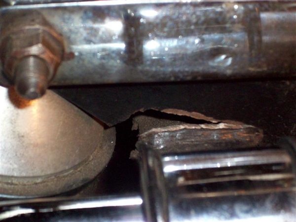
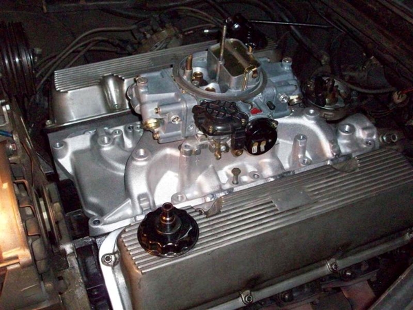
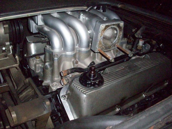
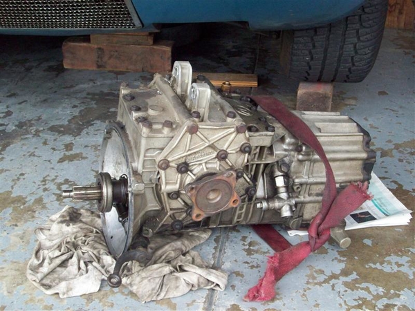
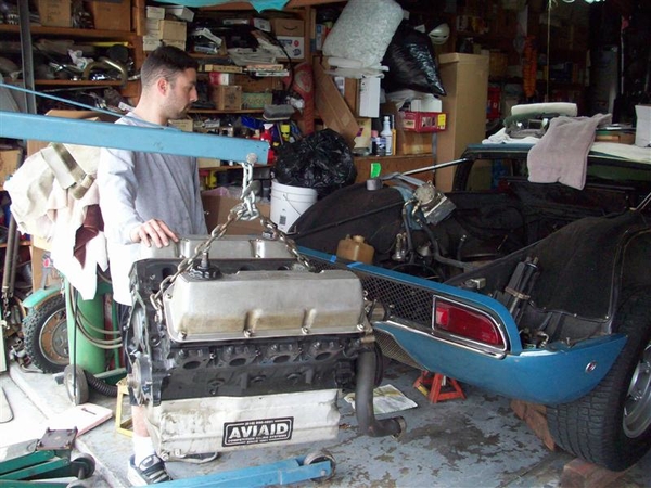
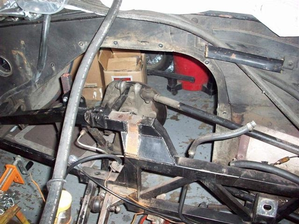
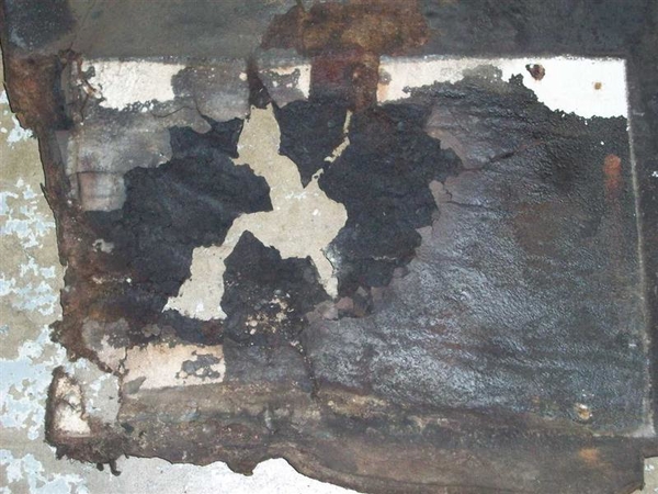
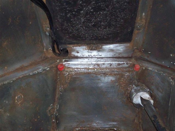
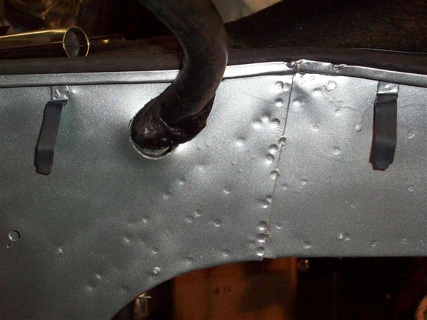
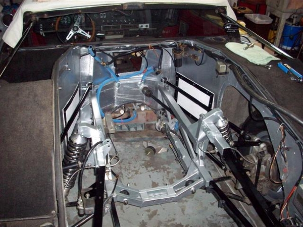
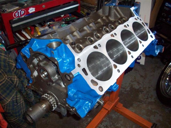
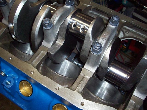
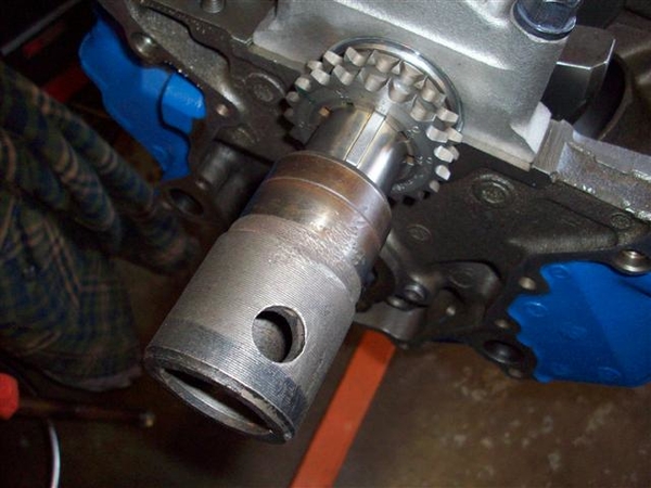
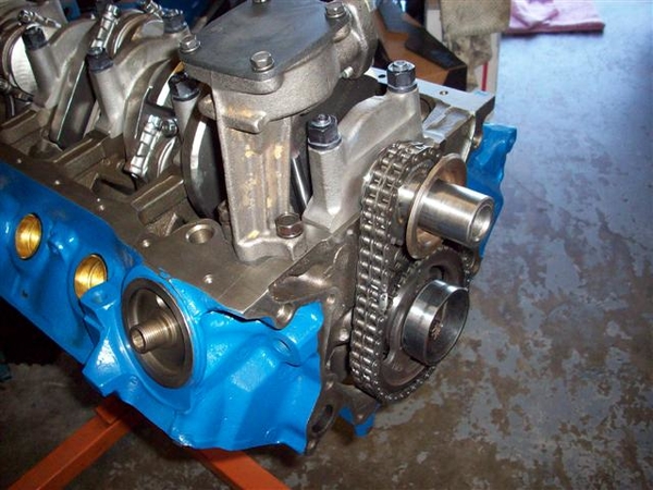
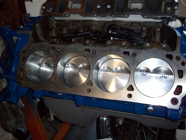
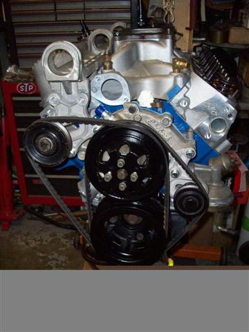
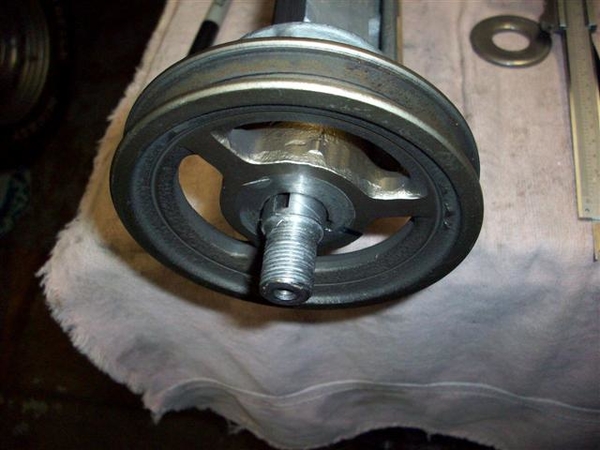
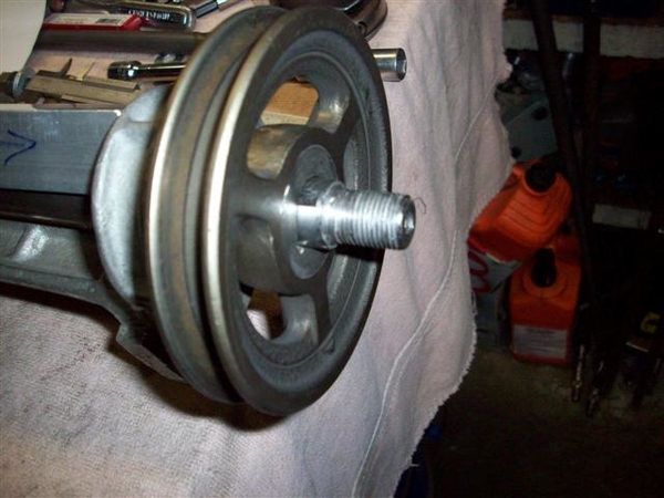
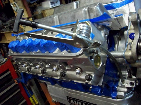
 NOTE IN THIS PIC Y0U CAN CLEARLY SEE THAT i HAVE FORGOTTEN TO PUT THE ONE PIECE REAR CRANK SEAL IN PLACE!!! THAT GAP IS HUGE!!! This will come to light once the engine is fired up for the very first time!!!!
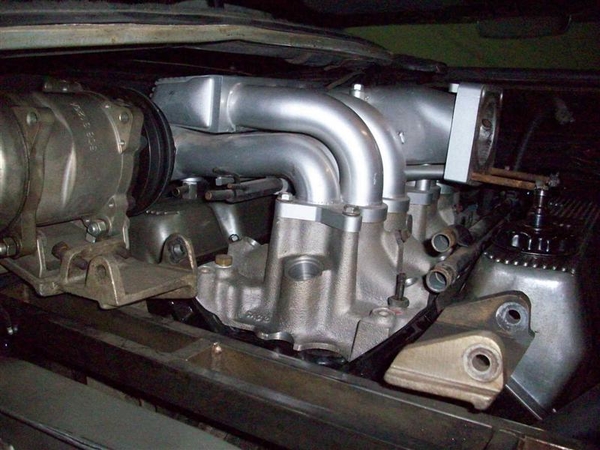