Hi guys,

rather then start multiple new thread I figured I might be best just to start one and title it with my own car's number. Then I can just add to it as time goes along.

Okay, car is registerd now and on the road, but I knew the Alden Eagle shockers weren't too good and needed replacing. I also need to do rear stub axles and a trunnion bush for the gear linkage. Whilst I'm there, might as well rip out the Upper control arms and send them to the UK for modification, and look at the steering rack whilst the UCA are away.

So there's the initial list. Got to start somewhere hey?

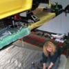
So this morning I ripped out the Alden Eagles. One out of four was still working, one had blown the lower compression valving out completely, one was actually torn in half and the front right had just stopped working.

So I have these on the ground, stripped and cleaned ready for transport to USA.

Question?

These were fitted new in 2004 and the car hasn't done 5000 miles in tht time. Given that now it's Down Under, it may get driven a whole lot more and on a variety of roads, not smooth super highways like we see on USA TV shows!

So, if the guys at Aldens rebuild them, I wonder if it's possible to harden them up more that what they might do for a show car for instance?

Do any of you guys run ALden shockers, and if so, are they sotock, rebuilt or have stock adjustables got enough ajustment to firm them up for the type of driving I'm proposing?

NEXT:

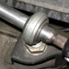
I'm going to send the upper control arms to UK for modification for castor. I've gone to pull them off and suprise, suprise, you need special tools.

I sorted the rubber grommet and found that above the clutch pedal, but the nut is lower than the hole centre so you cant use a socket from inside the car anyway.

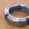
The worst part appears to be the 17mm bolts/nuts that actually hold the ball joint to the upper control arms. None of my 17mm gear will go on to them. Looks like you need a special super thin wall tube spanner to get onto them. Can anyone confirm the two techniques to 1. get the 19mm bolts of the upper control arms, and 2. what tool to use to get the 17mm ball joint off the upper control arms?

Thanks
Original Post

Replies sorted oldest to newest

Okay, shocker question still stands, but.............

Some days I just hate women!!!

Picture this. Her, the lanky blonde wife, arrives home after work and wanders into the shed with the business jacket, tight skirt and high heels.

"Are you still under that car?" she says, "You started that when I left this morning!"

So I explain to her that I got the shockers off and show her the cleaned up struts ready to post tomorrow, and then tell her that I struck an issue with the upper control arms etc as described in post above.

"What about that set of special sockets with the covers on them that I bought you to take the wheels off the cars without scratching them?" she says. "Isn't the smallest one of those a 17mm size?"

Yeah, yeah, yeah, but it's too thick to fit in this space I try to explain to her.

In her best, I'm only a mere woman and you are Tarzan type voice, "Well, what about if you slide off the nylon sheath that protects the wheels, then I'm sure you will be left with a thin enough wall to fit in there" she says, looking towards the roof of the garage as if to add 'dumbass' onto the end of the statement if she wasn't actually a very well mannered lady!

And guess what.............she was right. Three minutes later I've got both upper control arms on the bench.

Yes, she went and changed clothes then operated the 1/2 drive rattle gun from under the wheel arch, whilst I crawled into the footwells and captured the 19mm nuts. Bloody women!!!
quote:
I have aldins in mine, and mine are in simular condition to yours.

IMHO, from what you both have experienced, it might seem as if putting stock and faith in the virtues of rebuilt Aldins is pretty much an exercise in throwing your money away.

I cannot recall other failure reports with the Aldins, but the writing on the wall seems pretty clear.

Dump them now, buy Konis, and be done with it.

Larry
I've heard of a few Aldan failures- mostly leaks around the damping adjust screw. If you send such back to Aldan, they unscrew the adjuster and put a new 0-ring on. Until the next time. Had not heard of hard-part breakage before. What spring rates do these assemblies have?
Our Pantera has always had Konis with zero failures in going-on 30 years.
Okay, based on feedback from the guys that know, I went to Koni in Melbourne to discuss the issue. Now this is the Australian HQ for Koni, yet they tell me that the only product that they list for Pantera is the 8211 series which is a 12 stage fully adjustable rebound and compression shocker as fitted to all 70's and 80's race cars including F1.

It seems they will do the job, but their recomendation is the Code 1324 version with the B3 valving which suits a 285 - 450lb spring rate.

My car runs a 400/650 spring rate which they think is too stiff for the car, and if I stick with that spring rate then I need a Code 1324 with a B6 valving rate suitable for 400 - 700lb springs.

Now here is the kicker, $1100 AUD pr shocker plus labour charges to adjust the valving to suit the car and shorten the bump stops as required.

Close to $5000 for the set including new springs.

They said that if I could find an old set of Koni's, they can certainly rebuild them, but there are no suitable bodies available as new items apart from these racing shocks.
I have Konis supplied by Quella.

I took the following # off mine - 30 1301 1000.

'30' referred to the series 30 shocks, (gas-filled, sealed and not rebuildable)

1301 was the style (oval track with heim
joints for the upper/lower mounts

1000 was production date code (10th week of
the year 2000).

These are rebound adjustable shocks that must be removed from the car to be adjusted according to the factory sequence.

Springs are also from Quella and are -

GT5 SPRING RATES ARE:

FRONT 450 POUNDS

REAR 550 POUNDS


Hope this helps at least a little bit.

Larry
Yep, they look great. The 30 series won't do it for me as they are not height adjustable. Classic garage has a set for a good price, but I'm not interested in a fixed height unit.

The ones on that link look great. Weird that they are not Koni colour as I've never seen a Koni in Yellow, but if I could get a part number from them, I think they would be perfect.
Have you looked at the Hall Pantera shock options, they have both standard and aluminum versions...

http://hallpantera.com/cgi-bin...ntera-inc&item=22484

From the Hall Website under "Chassis Components"...

SHOCK ABSORBERS
Set of 4 gas filled shock absorbers with adjustable ride height. Includes springs.
$1040.00

SHOCK ABSORBERS
Aluminum, gas filled, double adjustable. Includes springs.
$1440.00

Might be worth making a quick call to a vendor or two to see what they have to offer.
Yep, I'm pretty sure they are Aldans.

But.........is that such a bad thing. If Hall supported them and sold them, can they be all bad. Seems a lot of folks using them that want height adjustment.

They may not be a Koni by design, reputation or quality, but are the Q1's going to be much better given their racing heritage.

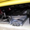
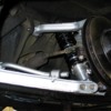
Here's what I found when I pulled out the Aldans. Remember these were fitted in 2004 and then a spring rate change was done in 2007 so they were obviously out at that time.

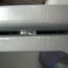
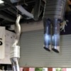
• Front Left - The entire adjustment knob and valve unit is not in the base of the shocker and I can't even see the groove where the circlip sits that holds the valve.

• Front Right - Not too bad, still holding pressure but doesn't seem to be affected by the adjustment knobs.

• Rear Left – No pressure at all.

Attachments

Images (1)
  • 01
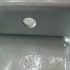
Rear Right – Very badly damaged. The entire shocker had come apart in the car. The top had come off and the inner tube has been rubbing against the casing and worn the thread off the outer casing. I have no idea how this could happen when the shocker is totally captive in the car unless constant movement can unscrew the top cap.

Attachments

Images (1)
  • 03
quote:
Originally posted by OzGT5:

The ones on that link look great. Weird that they are not Koni colour as I've never seen a Koni in Yellow, but if I could get a part number from them, I think they would be perfect.


You can just order the set from Pantera East and they bolt right in. I think the setup was only around $1000. Ride height adjustable too!
I've had trouble with their website recently too, but found this info posted by Larry late last year...
--------------------------------
A recent phone call found that he is redoing his website.

Try his phone or email:

727-381-1151 sales@mapenterprises.net

Marino is the owner

--------------------------------

Just found some other possible e-mail addresses for Marino on the POCA forum

marinoperna(at)ij.net mperna(at)tampabay.rr.com marinoperna(at)gmail.com
Last edited by 5754
quote:
Originally posted by OzGT5:
All Pantera East links that I have are dead.

Is there a new website for them please?


Be sure to tell them that you have a GT5 conversion so they can pre adjust the height for you. That said not all GT5 conversion have their finders in the factory position so some adjustment might be required. With my spring rates I left the back shocks set they way I received them (lower A arms parallel to the ground) and the lowered the front some to provide a slight nose down rake.

Mike
After much contemplation I decided to have the Aldans rebuilt.

Local Koni supplier in Melbourne was close to 4 grand for new ones, so back to CA they have gone.

Aldan recommend their S specification which is more suited to Sport Car / Road Race with heavy compression and heavy rebound settings.

They left yesterday so should be in California for the start of next week.

Whilst that's going on I have sent the upper control arms (front) off to Johnny Wood in the UK for modification which he did over Easter and sent them back today.

One thing of note is that apparently I already had an offset bush in the upper arms which now wont be any good so I have to locate some standard upper control arm bushes.

Can anybody point me in the right direction for these please?

I'm also having a set of short bumpers made by Kirk Evans and have already removed the rear steel bumper and shocker system all ready for the lightweight rear bumpers.
Today I also removed the rear axles. As you may remember I did a temp repair to the drivers axle a few months back to get the car on the road. I used a two part epoxy mix and then machined it on my lathe to 40.04mm and fitted the bearing with a loctite product to get me by, knowing that at a future time I would have to replace the axle.

I have done 300 miles on the repaired axle and today when I pressed off the bearing, the epoxy area looks like new, zero damage. That stuff really is amazing when used properly.

Anyway, I measured up my axles expecting them to be 39.99 and original, but no, it appears they have been changed at some time.

Worst part is they are not even. Starting from the base of the splines I have 40.04, half way down it goes to 40.11, and then back to 40.02 towards the base.

The passenger side wasn't much better being 40.09 through the centre and then back to 40.04mm where the bearing sits on the outside.

Also, when I took the nut off the passenger side it was quite loose, certainly not requiring any grunt at all with a three foot bar on it. The drivers side was still very firm and took a bloody god heave, which was good seeing as this is the one I repaired a little while ago.

There seems to be many and varied opinions on the axle solution, and I'm considering even a different alternative and would appreciate your opinions.

We have a very good hard chrome place nearby who will grind the shaft, hardchrome face it, and then grind back to my specification. Cost is around $220 AUD per side.

I contacted a local bearing supplier today who said that they would like to see approx 0.003 - 0.004 thou of interference fit on a 40.00mm bearing.

Calculating 0.003 thou back to metric brings me to 0.0762mm or 0.004 thou to 0.1016mm

This is really a lot, it means the shaft would need to have a finish grind of 40.075mm if I run with 3 thou interference fit! Seems too much to me, but I'm wondering what you guys think?

I would have considered 40.06 to be a suitable number, then warm the bearings, freeze the axle and slip them together.

Has anyone actually measured the bearings to be an exact 40.0000mm?
On a side note, I fitted new front rotors and pads to my Testarossa a couple of years ago and a few blokes here talked me in to having them cryogenically treated.

Frozen to -270 deg C in liquid nitrogen and then slowly bought back to ambient. Aparently it aligns the molecular structure of the steel and dramatically lessons fatige and structural failure of steel components.

My brakes are great, no disc scoring at all and hardly any dust.

At the time the guy had hundreds of mower blades from the large municipal lawn mowers. Apparently after treating they keep an edge for 8 - 10 times longer than untreated.

He was doing gearbox splines, axles, aircraft components, all sorts of things.

http://www.cryogen.com.au/ will take you to the site.

Today, my local Ferrari mechanic suggested that I do the Pantera axles after the chrome and grind treatment.

Do any of you Americans use this type of treatment or have any experience with it?
Thanks Larry,

Given that my current axles are 40.04 at the bearing end, wouldn't you think thay have been replaced at some time, as I thought factory ones were actually undersize, like 39.99mm?

I'm concerned as to why mine appear to be much thicker in the middle, meaning I'm stretching the bearing somewhat to get over the centre and then going back down to 40.04.

Could the axles be getting thicker in the middle by the tension applied to the nuts?

Are the Wilkinson axles made to really good tollerances in your estimation?

Would it be possible to get a current price inclusive of post to you from Wilkinson as trying to get the time right between the countries is hard.

BTW: I also need that strange bush that sits on the drivers side chassis rail that the gearshift shaft runs through. Mine is so bad it has more than 6mm of sideways movement and I've had to take the finger gate off to allow gear selection of Reverse and first.
I wrote to Steve Wilkinson today to see if he can confirm the shaft size of his axles. I really want to go with a 2 thou interference fit to the bearings and if I can't buy this then I may have to go down the spray weld route. After 35 years, the old girl deserves a new set of axles, so I hope that the Wilkinson axles have the right tollerances.
Last edited {1}
quote:
I also need that strange bush that sits

Trunnion bearing. Stocker is pretty well done for after 35 years.

All the vendors have it.

Quella does something different on his restorations. He removes the shaft and welds a larger pipe over the area where the trunnion is. He then turns that new o.d. down to fit properly inside a large heim joint.

No slop, but a bit problematic for keeping lubricated.

A local owner bought the axles just late last year. I recall the bill was just under $400. Doubt it has risen since them.

As for tolerance, I do not have measurements of the set I bought, but I am quite sure Steve had them made for a proper fit.

Larry

Attachments

Images (1)
  • Picture_5
Larry, I tried to sign up for Steve's subscription today but the sign up link didn't work at all.

It's pretty hard to find anything there except, naturally, for the stock parts that come up on the catalog diagrams.

Is there a specific link to an area on his site where he lists all the new stuff, like these axles etc?
quote:
It's pretty hard to find anything there except, naturally, for the stock parts that come up on the catalog diagrams.

Steve's site has not, nor is likely to be in the foreseeable future, upgraded since created.

But some of his new parts have been added, and are findable by going to that piece's description page, and deleting the last letter and adding the next letter.

He is in effect creating a new part number. Sometimes he adds several,so keep changing the last letter until you get a void page.

Not so with his new axles.

For instance:

This is the page number you get for one of the coolant pipes

http://www.panterapartsusa.com...l.cgi?prod_id=11007A

If you change the last letter "A" to a "B", you get his upgraded stainless steel pipe

http://www.panterapartsusa.com...l.cgi?prod_id=11007b

Larry
Still no joy here. No answers back from Wilkinsons as to the actual external size of their new axles.

Car is in a million bits and whilst waiting for answers so that I can order my bits from USA, I've started cleaning up some of the underbody bits.

The previous owner stated in the car records that all of the control arms were bead blasted and coated back in 2007 when new bushes were fitted.

Doesn't ring true to me as ALL of the control arms have surface rust on them. Sandblaster took it all off and the paint was so thin, I'm sure it was a $2.95 spray can from home depot. Certainly not a decent paint let alone a powder coat.

So having sand blasted them all again, this time they are all getting a proper priming and coating with 2 pack enamel in an alloy colour. I've also pulled off the rear stabiliser bar and I'll have this powdercoated as the spring tension in it wont take kindly to chrome plating or even painting.
Pantera and Mangusta stub axles need a medium press fit if you're going to use ball bearings or straight-roller bearings such as the GT5-S had. Slip-fits do not hold the inner race tightly enough for 300+ horses with these bearings. The axle will flex a little and the steel used is much softer than bearing race steels, so the axles get wear-tracks pounded in them.
I've seen stock axles successfully repaired by welding, by hard-chrome and by spray-welding. Once repaired and reground (NOT lathe-turned!) to a medium press fit (0.0005"), ball bearings will last a lifetime.
But if big wide sticky tires are mounted AND you drive hard or do frequent track days, expect to find the second weak spot in stock axles. This is the wheel flange where it joins the axle shaft. The flange will flex at the shaft with giant tires, eventually cracking in two and you lose a wheel- and usually, the lower rear quarter panel! This doesn't happen with normal street use but 3 continuous hours on a race course with race tires will usually break one or both stock axles. Most aftermarket axles do not have hollow shafts, and have 3X thicker wheel flanges. Such non-flexing axles are adequate for pro racing with over-600 bhp engines. Knurling or magic glues will be very temporary axle repairs if you drive the car as it was intended. Finally, all this is useless unless you check axles with a 4-decimal micrometer: 3-decimal micrometers simply cannot measure close enough to check a medium press-fit of 0.0005". You'll be guessing which usually doesn't work. And remember, axles and the bearings are made with tolerances. Its possible to find completely stock combinations that are loose, tight or just right, but it takes a lot of parts to sort thru to find the 'good' combinations. Better to get high-quality high-carbon steel aftermarket axles and put that worry aside forever.
With you all the way and understand that Larry.

I just need an answer. Do I just buy a set of Wilkinsons and be done with it?

Are they the right size?

I have to worry about this when a guy here in Perth ordered WIlkinson axles and they are 39.995mm measured properly.

This is undersize to the bearing so as long as it's seated parallel, it's barely a press fit as it's undersize.

Checking my imperial back to metric, your 0.0005" comes back to 0.0127mm

To get this crush inside the bearing I need to confirm that Wilkinsons new batch is 40.0127 or pretty damn close.

As soon as I see 39's, they just can't be right.

By the time I get them here, and slip new bearings in, it's a $1000 job, so I must get it right. You guys are too far away to do it again, and the mail is a killer on heavy things.
quote:
With you all the way and understand that Larry.

I'm Larry, but Bosswrench is Jack. Smiler

Of course, if everyone (Including you Wink) would just sign your postings - like folks used to do in the old letter-writing days, sigh - then we would know who is who a bit more easily.

quote:
Do I just buy a set of Wilkinson's and be done with it?

Are they the right size?

Steve is closed Mondays. I will call him Tuesday and see if he gives me a clear answer to the size question.

Stand by.

Larry
Well I completed the rear control arms today. All shiny and new in their new coat of metalic silver paint. I used a special hardened enamel designed for wheels as it's got great adhesion properties and resilient to chipping.

I have one hub stripped out and ready to go and will do the pass side tomorrow.

My front uppers should be back from Johnny Woods tomorrow or Wednesday so by the end of the week I should have all of the control arms painted, rebuilt and ready to fit back in again.

Hopefully Aldan turn my shockers around nice and quick so I can get it on the ground soon.

I need to check my steering rack for play but can't really do this till wheels are back on and the weight of the car is on them properly. Then I'll have the wife rock the steering wheel whilst I have a good look and see what else is needed.

Then I can order the trunion bush, axles, and maybe steering rack rebuild kit all at once.

I have also ordered Kirk's shortened bumpers to give it a cosmetic lift at the same time.
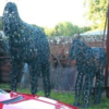
I searched Oz for a decent Testa and couldnt find one so I went to UK and bought it. That sculpture is in a small town called Heydon in Norfolk. Apparently after the Crusades, my family owned a castle near there and this village supported the castle.

Those sculptures are outside the local blacksmith shop in the village. Look great don't they?
Did you look thru the technical pages Larry.

There's a bit of info there on how to fix these Italian beasts as well.

They are prone to all sorts of issues, but it's been fun learning how to fix them.

And now I start all over again with the elder cousin!! Glutten for punishment I think.
And a couple of issues I discovered along the way.

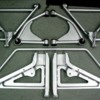
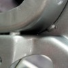
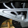
The lower front control arm has been pressed and assembled from two components. It's then been welded together but the seams between the pressing can catch and hold a lot of road debris, which stays wet and can cause cancer in these areas.

If you ever strip these down, pay particular attention to these areas. Get them really clean, sandblast, scratch, do whatever, but get the crud out of these seams. Then treat them with a rust converter product like ferrite tannate solution before you paint them.

I'm actually going to use a grey coloured mastic filler over the paint and carefully apply it OVER these gaps to stop the crap getting in there in the future.

Attachments

Images (1)
  • 4210
They don't show in that pic as they are on the underside of the a-arms. I was just curious if you had them.

I see that you have a nice ding in the rear lower a-arm. I have a similar one on one of mine. It was probably from some tire jockey in the early days.

I also went through the same scraping and cleaning on my front lower a-arms. That area trapped a lot of dirt and gravel.

John
I wrote to Precision Performance yesterday and had a reply straight back from Bob.

Most interesting, quoted below for the information of anyone looking for axles.

"We have been doing this since 1977. These other people keep trying to change whet has always worked. The axels we make press into your bearings like they are suppose to. They never did from the Factory or from all the others made. I guess they never figured it out.

So here you go 1.575 +.0008-0 That means 2000 press on to the bearing, any more and its to big to press apart later.

If you get this kind from any one else you still get them from me as I'm the manufacturer of almost all parts made.

Pantera by Wilkinson has them made in China and they are too small and spin."

Looking at their website, (http://precisionproformance.com/sc2014.htm) they say that the axles are 4340 billet steel, and can be supplied as stand alone axles @$375 USD per axle or complete kits with bearings, spacer and nuts @ $475 USD per axle.

Has anybody here used or have experience with the precision performance axles. All the answers appear to be right, but I'd like some feedback before I drop $1100 Ozzies in the hole!
I had a reply from Steve Wilkinson today. As you guys said, he was in Italy at the factory.

"LET TALK ABOUT YOUR AXLE PROBLEM! FIRST OFF LET ME STRAIGHTEN THINGS OUT ON DETOMASO MAKING THE AXLES THE WRONG SIZE. ALL THE AXLES THAT CAME IN THE PANTERA WERE THE RIGHT SIZE. FORD MADE A RUN OF AXLES IN 1972 THAT WERE UNDER SIZE BY .002. THEY WERE STILL OK TO RUN BUT YOU HAD TO INCREASE TORQUE ON THE NUT TO 420 LBS. WE STILL USE THE TORQUE OF 420 LBS ON THE NEW AXLES TODAY. YES, YOU SHOULD USE NEW AXLES THE DOUBLE BEARING AND A SHORT SPACER. THERE IS NO MOD. THAT HAS TO BE DONE TO INSTALL THE DOUBLE BEARING."

So still no confirmation of the finished sizing of a Wilkinson axle but I've replied and asked again as the last thing I want to do is have a set of axles sent to the other side of the World only to find that they are either undersized to fit the bearing correctly, or worse, have some taper to them.

This research takes such a long time. Poor old car is missing out on a run of Autumn 27 - 30 degree glorious days. Bugger!

Still haven't recieved my front upper control arms from Johnny Wood either. He posted them ages ago, bloody volcanoes!
My Percision Proformance axles arrived today. They look pretty darn nice. Looks like the rebuild can commence now. My repaired shcokers also arrived back from Aldans.

What a great bunch of guys. They found that two shockers had issues which thye felt related to manufacturing, so they replaced them. The other two had worn (actually bent) shafts in them so they fully rebuilt them with all new parts internally, charged me $100 and sent them back again. Fantastic service and highly recomended.

Question: What would cause three shocker shafts to become bent?
I rolled the old shocker shafts on a laminated board and the bend is just discernable.

The car originally had 350 / 550 springs when the shockers were fitted, but were changed in 2007 to 400 / 650 springs. Maybe the original springs bottomed out sometime?

Aldan have set up the replacement/rebuilt shcoks to an 'S' sprecification. This is a road/rally spec with much firmer valving than previously.

Hopefully these will be better and I might gain a better opinion than Julian's. I'll let you all know.
Hi guys, I've put the front end back together with Johnny's arms and it all looks great.

Went to make a start on the rear end tonight and noticed the MIN THICK 17.5 on the rear rotors.

Mine appear to be in nice conditon, virtually no scoring at all, and measure up to 17.82mm.

Can anybody tell me what the thickness is for a new set of rear rotors? This axle replacement is quite a big job, and I don't want to have to do it again if I find out that I'm really close to min thickness on the rotors with barely one skim left in them.

My fronts measure up 20.38mm but I can
t see any MIN THICK writing on the fronts so I'm not sure what's good and what's bad for the front.

So I've put the rear on hold until I sort out the thickness issue. Besides, it's too cold in the shed these last few nights anyway.
Just going through the workshp manual, which is all in imperial for some reason, and there are a number of sums written there for New and Refinished sizes.

Front - new 51/64" refinished 43/64"
Rear - new 47/64" refinished 39/64"

Hard for me to understand this so using the old grey matter calculator i thought I'd run a mathmatecal equasion over this to convert back to metric.

As an inch = 25.4mm I did the following:

25.4 divided by 64 multiplied by 51 gave me 20.24mm

Similar calculations gave me the following:

Front new 20.24mm refurbished 17.06mm
Rear new 18.65mm refurbished 15.48mm

Now someone please check the figures because this doesn't make much sense.

The rear solid rotors on my car certainly say Min thickness 17.5mm yet here's the factory manual telling me that 15.48 is the min.

Interesting also to see that Larry runs a stock DT fonts that say 19mm on them and here's the manual saying 17.06 min on the front.

Nothing is ever easy is it?

I'm trying to sort this out for two reasons.

1. The rear axle job is so intensive, I don't want to do it again in a year because my rotrs are down.

2. Rotors and pads are common wear items that must be available down here. They are probably shared with some other car and available from EBC dealer locally. I just need to go to EBC with the right dimensions and have them match up a set of rotors for me.
That's great Larry. Vented rears as well. Excellent.

The 121.61053 says that it is a C-Tek standard rotor.

The 120.61053 says that it is a Premium Rotor - Preferred. I take it that they are better in some way?

You used a front Mustang rotor on the rear and found it to work just fine?

So both numbers are from the FRONT of a Mustang?

Measuring my rotors, the height of the hat from face of disc to mounting surface on the front are 36mm yet the rears are 40mm. This 4mm variation seems a lot and I would have thought that it pushed the centre line of the rotor back 4mm in towards the centre of the car?


Your Mustang rotors (as above) show a height of 58.6mm and a Nom thickness of 21mm, therefore giving a 'hat' height of 37.6mm.

1.6mm higher than stock fronts and 2.4mm lower than stock rears.
quote:
That's great Larry. Vented rears as well. Excellent.
Indeed

The 121.61053 says that it is a C-Tek standard rotor.
The 120.61053 says that it is a Premium Rotor - Preferred. I take it that they are better in some way?
.........As noted in the text, the company stated difference is said to be a better casting and a black paint 'e' coating. In my case, they both were the same higher grade casting, just one had the 'e' coating.

You used a front Mustang rotor on the rear and found it to work just fine?
.........Yes. Read the text with the photos closely. There is a diameter difference. It will result in some unswept pad on the rear. In practice, this is not really a problem. If it concerns you, take them to a machinist and have them turn them down to match the OEM diameter.

So both numbers are from the FRONT of a Mustang?
..........Yes, but again, read text closely. Due to continuing difference in suppliers, make SURE the #'s currently match to just the rotor, not the one-piece hub and rotor unit.


Measuring my rotors, the height of the hat from face of disc to mounting surface on the front are 36mm yet the rears are 40mm. This 4mm variation seems a lot and I would have thought that it pushed the centre line of the rotor back 4mm in towards the centre of the car?

.............I found the height of the new rotors to match the old rotors. They created no change in rotor position as far as centering in the calipers.

I was able to knock out the metric studs and drive them into the new rotors.

A very basic upgrade procedure with only minor issues.

Larry
Last edited by lf-tp2511
Out of curiosity I went and looked at my old rotors (found them in a corner of the shed!) they indeed say min 19mm front and both were 19.8mm. The rears say min 17.5 and they were 17.8mm, so I guess they really can go out to trash next week.

When I upgraded rotors and brakes I used two piece rotors and hats and moved the hats outboard to make for easy disassembly next time.

Julian
Well what a day it was.

After measuring, procrastinating, and then measuring some more, I took off to visit head office of RDA which is Rotors and Drums Australia, our biggest supplier and also a subsiduary of EBC (UK and USA)

The only DeTomaso listings were for a 1990 Pantera with huge discs, or discs for a Longchamp!

So then I followed Larry's advise and asked about 65/66 Mustangs. Every early Mustang in the catalog were hub mount style rotors with the wheel bearings integral in the rotor, like on a trailer. There were no floating discs listed for any Mustangs.

The guy at RDA suggested that www.brakewarehouse.com are probably manufacturing a hub system to adapt to a floating style rotor. That's why theu offer the various styles of rotor to fit the Mustangs. Unfortunately, not having too many Mustangs, this isn't an option here.

Rotors are too damn heavy to ship so I'm going to have to continue the hunt down here for a suitable product.

So.......still at the drawing board!
Problem down here is that we didn't have a plethora of Mustangs. We have a few now that they are old enough to be eligible for import, but certainly nowhere likely to have new old stock, or actually any stock at all.

I'll have to see if any other blokes come through with details of their brakes, ie: rotor diameter and thickness and top hat thickness and if they changed calipers to suit.

Given some more info, I'm sure I can find something suitable down here. Given my wheel size I'd like to have larger brakes under her anyway. I already have one Italian that doesn't stop, so it would be good to be able to slow this one down in half the distance it takes to stop the Testarossa......or better!
Not being able to locate a suitable replacement rotor for the car, I've decided to put it back together with the current rotors. Then I can take some accurate measurements of the caliper centred position, with and without pads in place, and then I can ascertain exactly what will fit onto the car.

For those Aussies out there, keep an eye on this thread for locally available parts when I can locate suitable rotors.
Work sucks! Keeps me away from the car.

Thanks to Australia still celebrating the Queens birthday, it's a long weekend here so we got a bit done on the car. Even the wife got into it, parked herself on the carpet in front of the pot belly stove and scraped 35 years of sludge from the half shafts and got them all ready to repaint.

Attachments

Images (1)
  • 0315
Quick question:

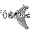
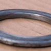
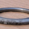
When assembling the rear axles with new bearings, there is a shaped washer under the split axle nut.

This washer has a taper on one side and is flat on the other side. The taper, to me, appears that it would face downwards to compensate for any casting irregularities in the head of the splined yoke. This would let the split nut sit against a perfectly flat face when tensioning to the required 400ft/lbs.

But........my washers may have been previously fitted upside down as there are marks on them where they have come into contact by the split nut.

Can anyone verify which way this washer should actually be seated?
But........

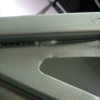
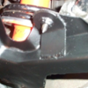
Here's the flange. Hard to see but the flange isn't dead flat inside as the casting shape starts to curve slightly. This initially indicated to me to put the washer in with the tapered side down so when it pulls up tight, the tapered part of the washer stays clear of the casting rounded shape.

Then the fully flat face of the washer must contact the split nut, and if that is the case, then why have the slightly raised section on the split nut?

Attachments

Images (1)
  • flange
quote:
then why have the slightly raised section on the split nut?

I've checked all my manuals, and the online sites. Nothing shows this in detail.

But, as you noted, it appears the taper side of the washer should go in first so it stays clear of the rounded shape of the flange.

As for the ridge on the nut, you wouldn't want the full face of the nut pressing on the outer edge of the washer, as the washer radius and the flange rounded shape radius are likely not an exact match. With just the raised edge of the nut contacting the washer, the nut's force is all directed squarely on the bearing area of the washer.

Does that make sense?

Hope I helped.

Larry
Well the plot certainly thickens. Larry thinks as I do, yet John is oposite, thinking that the two ground surfaces on the nut and washer should meet.

It's certainly an interesting one and I'm supried that it hasn't surfaced before. There are a lot of owners who have either changed axles or bearings or both and evryone must come across this sae issue.

I could just put mine back together the way it came apart, but I'm not convinced it was correct to start with.

Logic says that the job of that nut is to pull the flange down onto the bearing at 400+ ft/lbs.

If I sit the washer into the flange it's near on impossible to see if there is clearance to the tapered section of the casting.

If john is right and the raised section of the washer is parallel ground, then it would make sense to do as Larry says and put the washer taper down and tighten the raised section of the split nut down onto the flat side of the washer.

As you can see, my washers are marked pretty badly. Had they been assembled as suggested in the above paragraph, I would only se rotational scoring on the inner 3mm of the washer face and this would give me a good clue.

I have located a 3/4 drive torsion wrench so will try and do this job over the weekend, so if anyone can definatively solve this puzzle in the next day or so it would be most helpful.

Maybe anyone close to CA could give Bob at Precision Pro-Formance a call. I'm sure he could anwer it, especially given that he makes the axles and split nuts.
When we took two different cars apart (71 and 74) and the cupped side/relived side was toward the outside of the car. We assembled it the same way and have had no problems. I think it was designed that way to give a little extra clearance with the splines on the axle and yoke. You will notice that as you slide the yoke on the axel the splines are pretty close to the top of the yoke spines. If the spacer between the bearings has much wear the yoke can stop on the axel splines before the spacer is held tightly between the bearings. This also moves the full force of the compression away from the splined area on the yoke.

Not sure how well I explained this but hope you can follow the attempt.

Mike
Last edited by pantera1887
quote:
Larry thinks as I do, yet John is opposite, thinking that the two ground surfaces on the nut and washer should meet.

I'm not sure John is in disagreement with us.

He merely stated the two sides are parallel, implying that the torque applied to one side is evenly applied to the other.

Which is what we want to happen.

I think as long as the torque is being properly applied, then it becomes an issue of fitment.

And the tapered side of the washer would seem to want to be placed towards the tapered side of the casting.

I've got a call into Bob and he is supposed to call me back.

I'll update when I hear from him.

Larry
I agree with Mike's logic. If the taper were installed toward the yoke (toward the outside of the car), then the smaller diameter seating surface of the washer's tapered side would put the compression force very close to the splines of the yoke.

Inversely, if the taper were installed toward the nut (toward the inside of the car), then the compression force would be farther from the splines of the yoke.

Interesting discussion.

John
Post
×
×
×
×
Link copied to your clipboard.
×