

The fit was sloppy with lots of lead and lots of gaps. It's just the way they were. Many don't address it during restoration and it shows.
Looking good Rodney. Making crazy progess man.
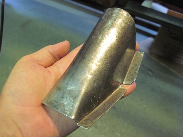
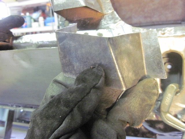
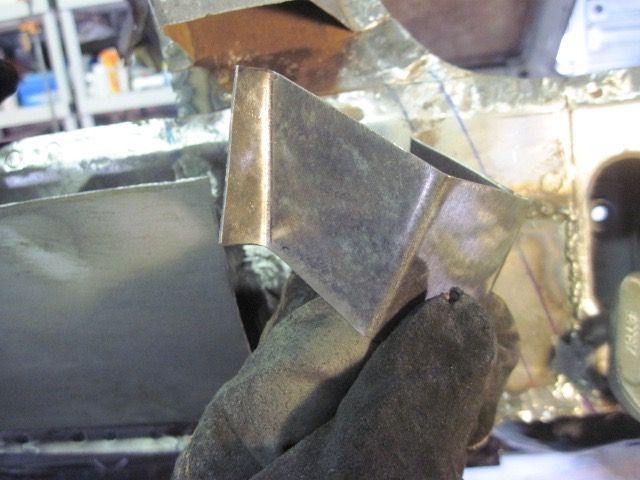
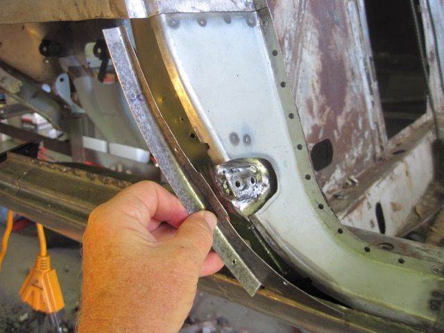
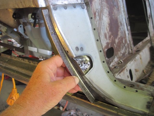
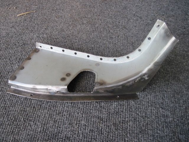
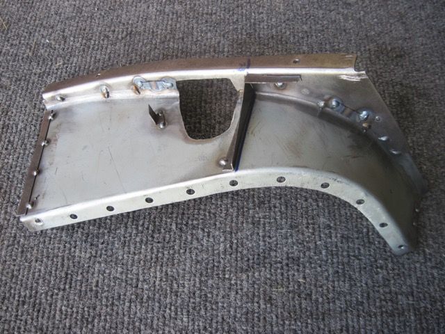
How did you get the curve in that piece? It looks perfect. Curious how you stretched and shrank the flanges to get such a nice finished piece.
Steve
Steve
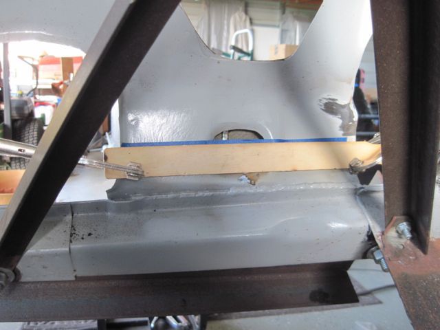
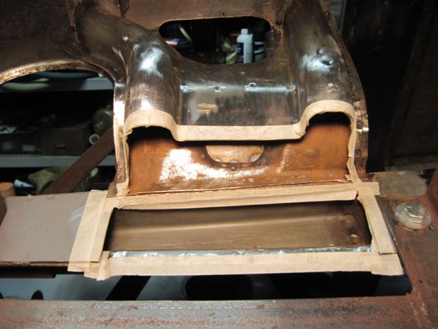
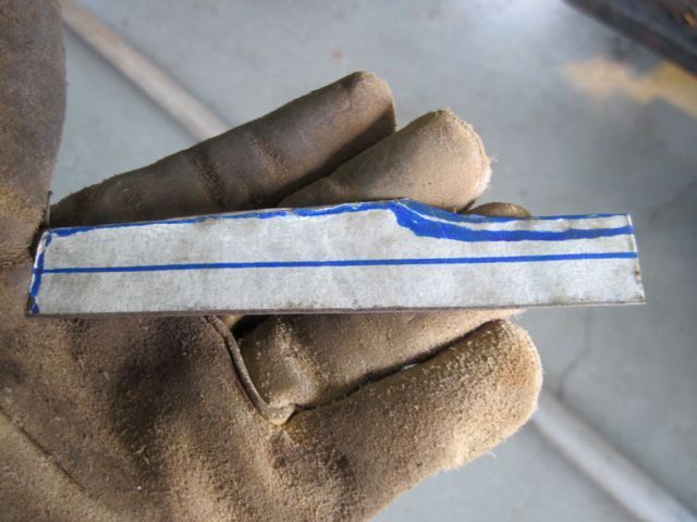
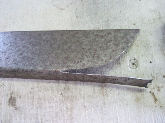
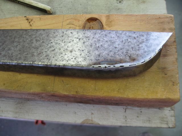
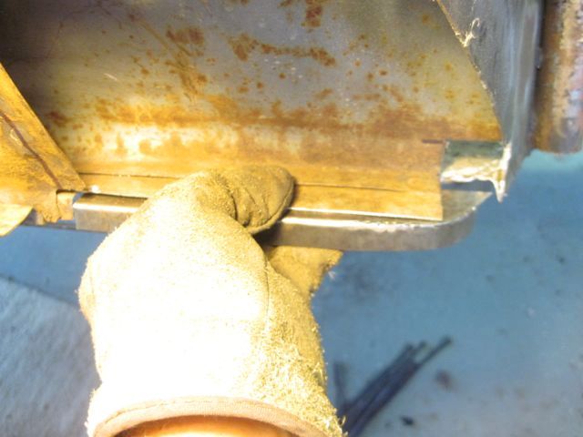
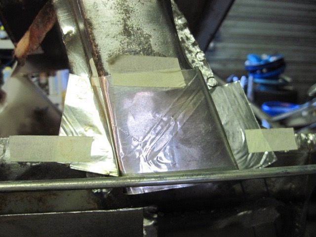
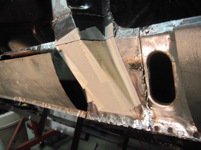
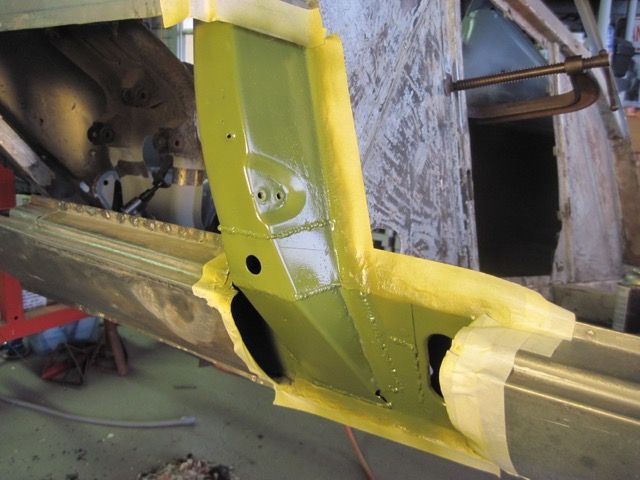
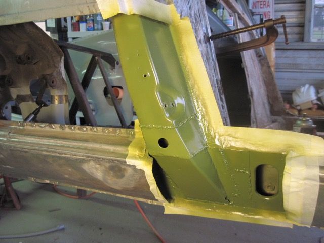
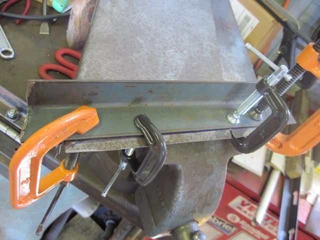
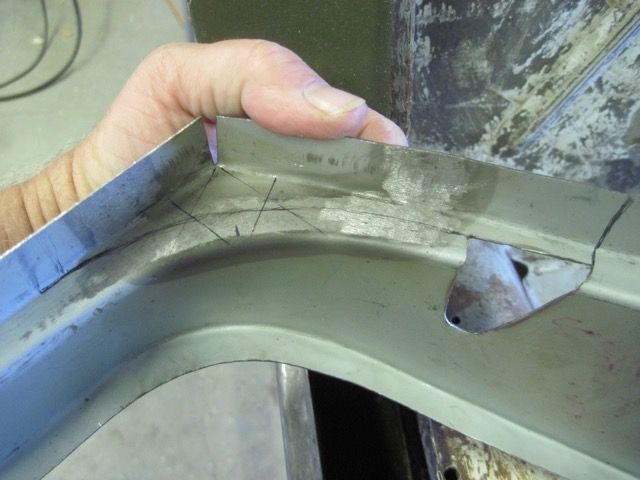
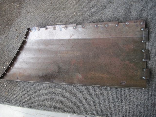
Funny you should ask, Steve. I bought the stretcher and shrinker tools from HFT. In the pic where I have the masking tape on the flat piece of metal, the outer flange has already been bent, so not easy to see in that pic. The inner flange is sketched on in marker. It is only 22 gauge, so it cuts and bends easily. I just bend the flanges to about 90* on the piece, then shrink the inside flange and stretch the outside one till the curve fits like I want it. Then trim off the excess if necessary.
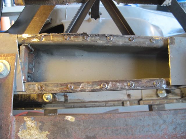
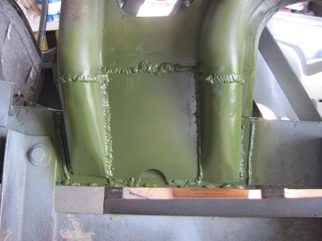
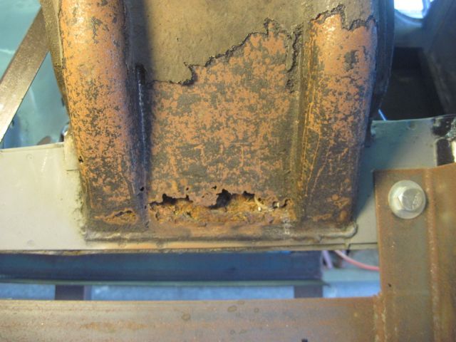
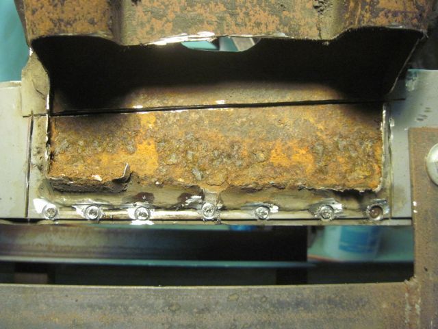
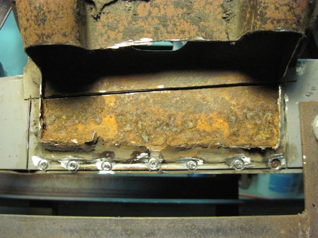
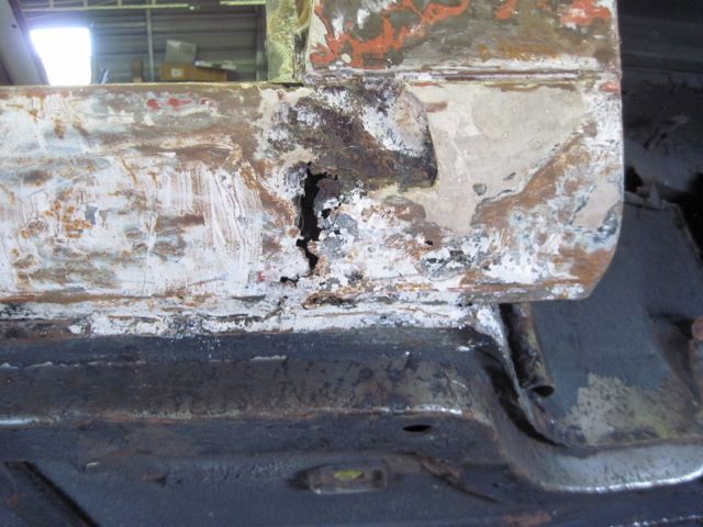
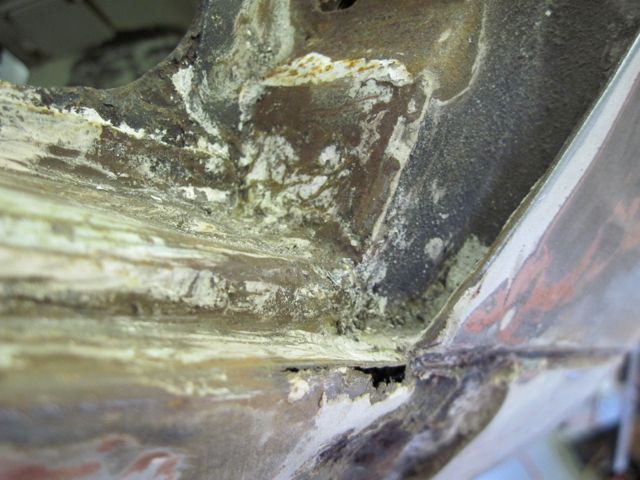
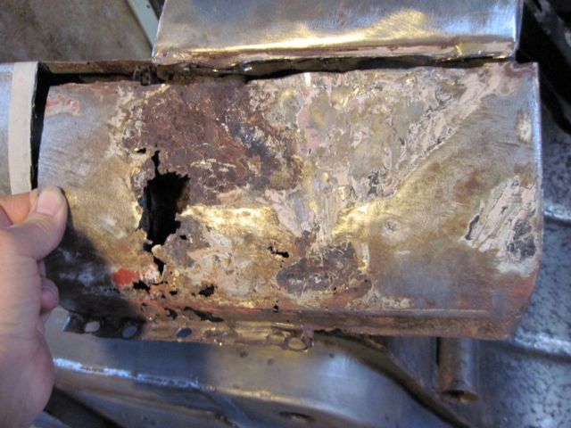
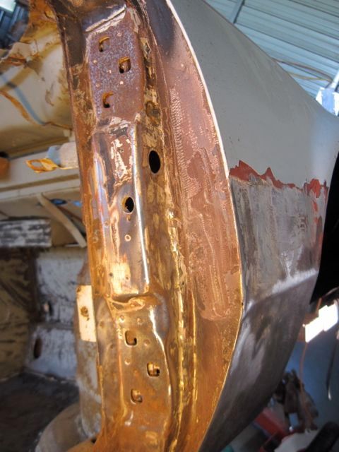
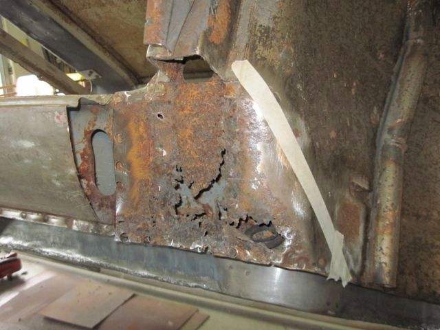
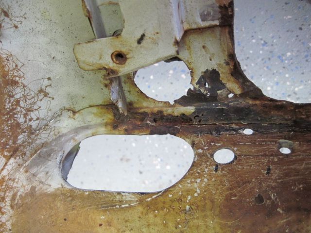
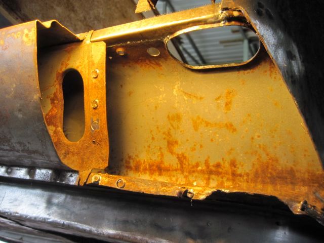
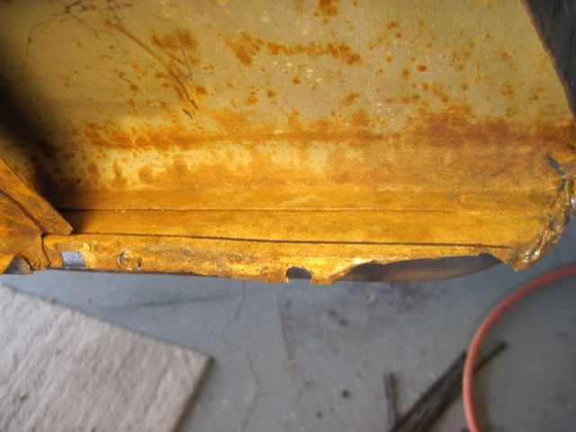
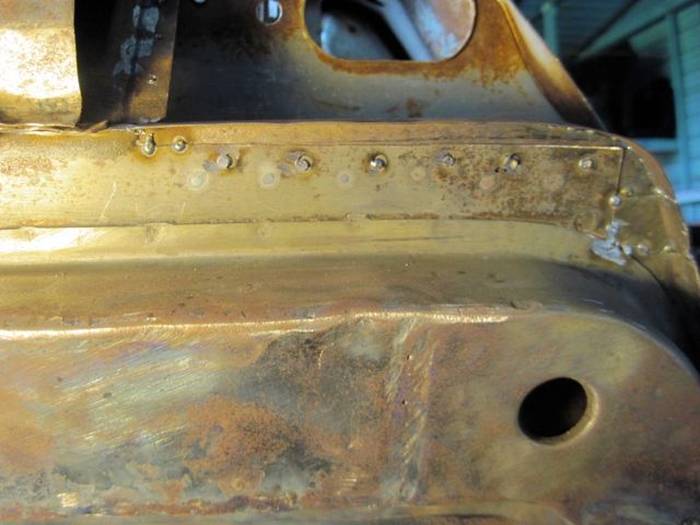
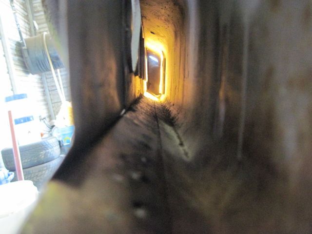
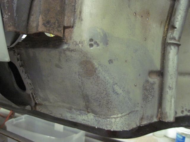
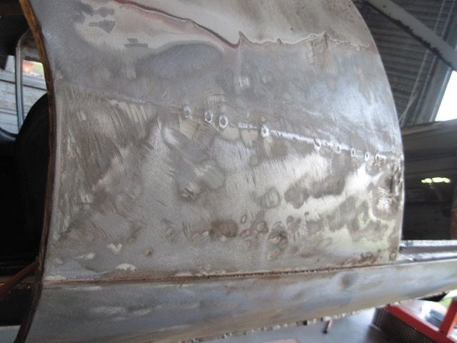
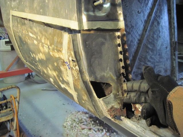
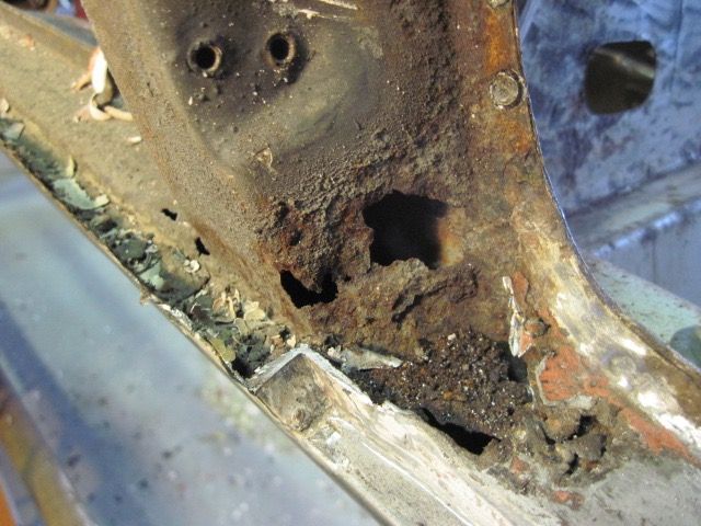
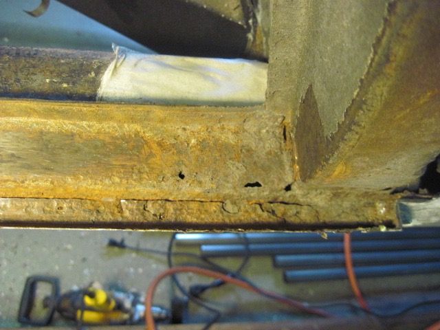
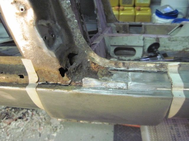
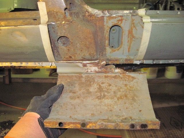
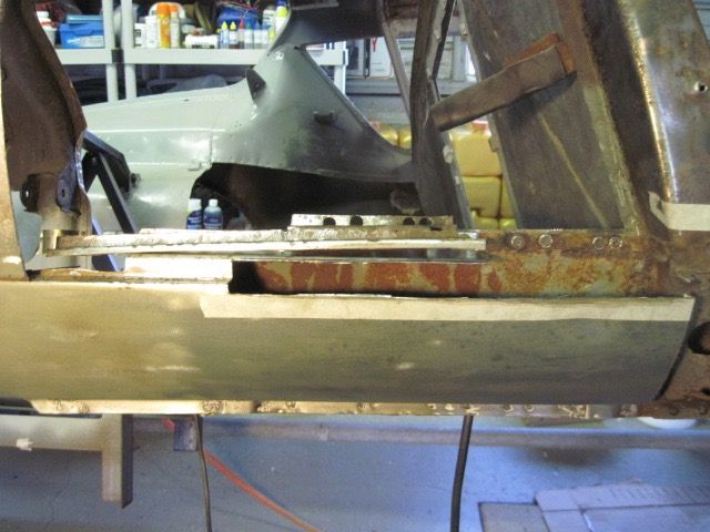
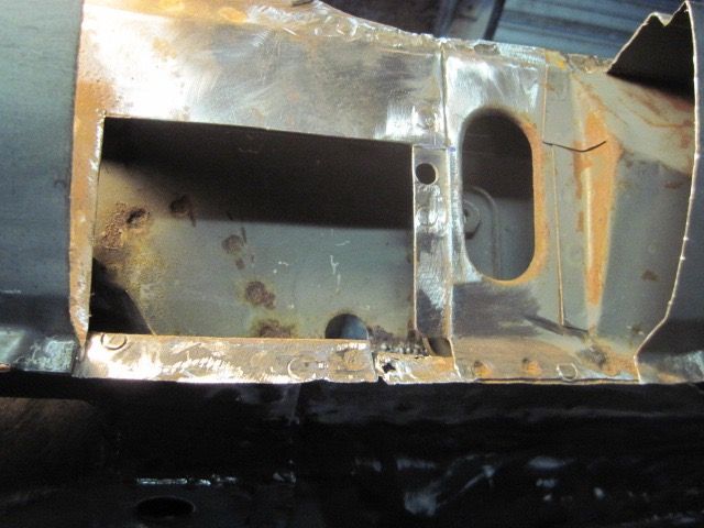
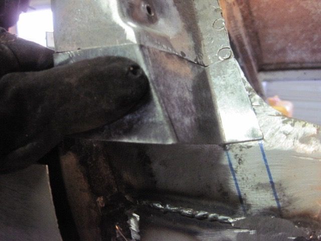
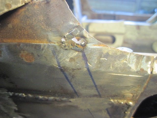
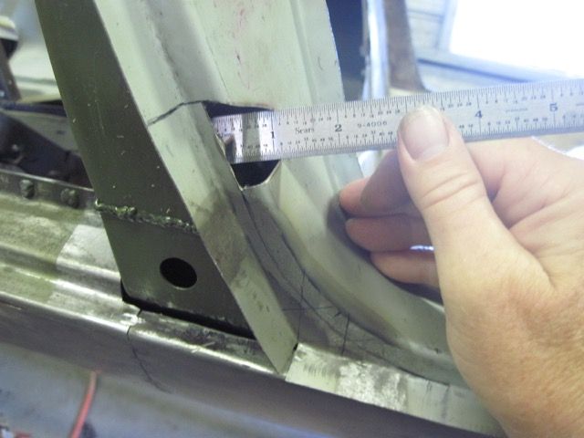
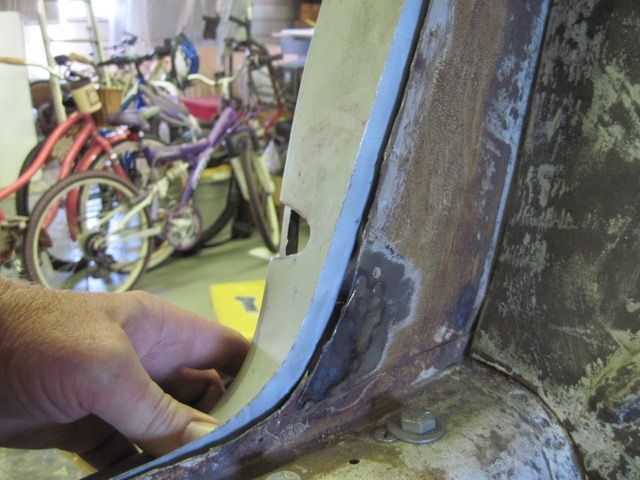
This is pretty much a text book example of rear wheelhouse structural rust. I used a panel nibbler to cut upward just to find where the rust ends, and I have sketched some marks about where I think I need to go.
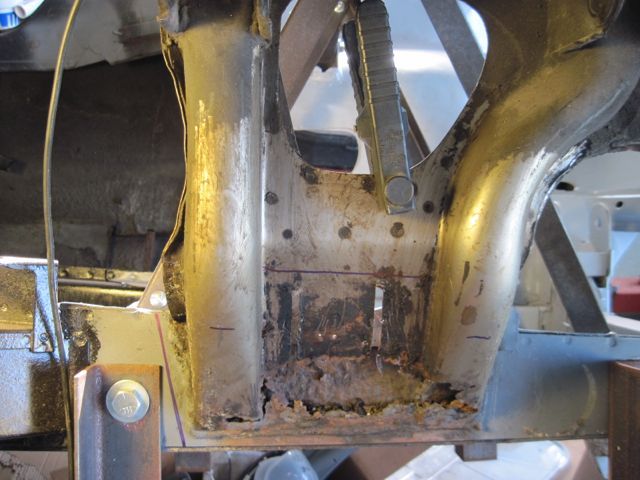
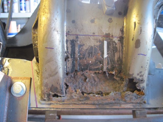
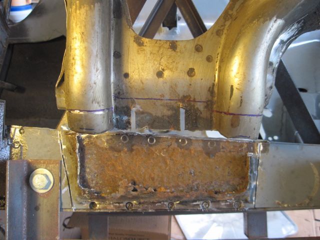
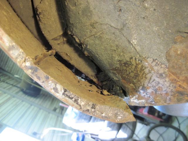
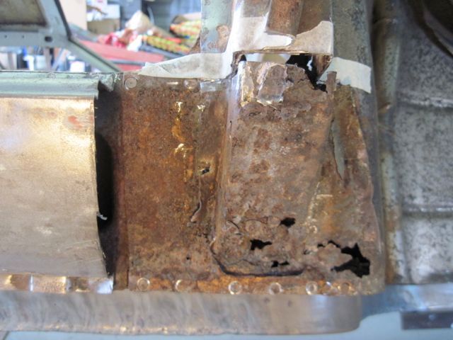
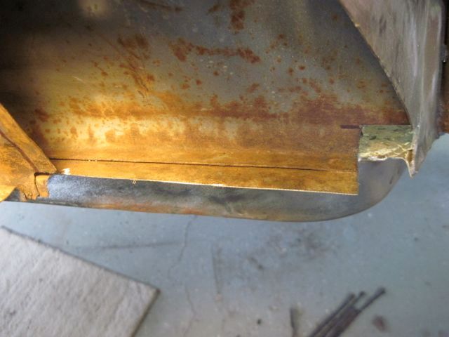
I used the plasma cutter here, since I could see this was trashed pretty much through and through. A little collateral damage is no big deal.
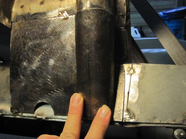
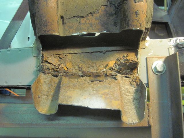
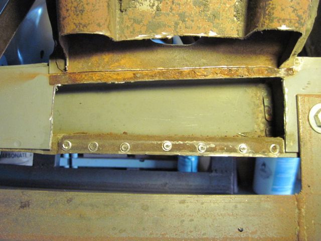
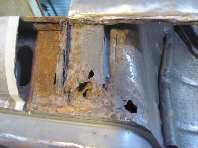
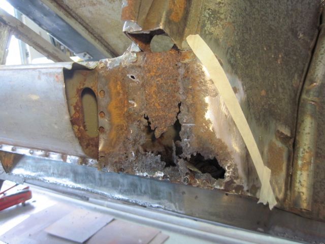
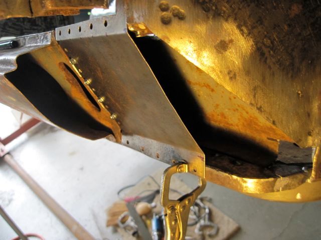
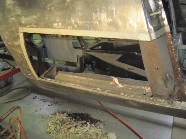
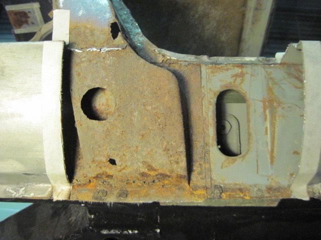
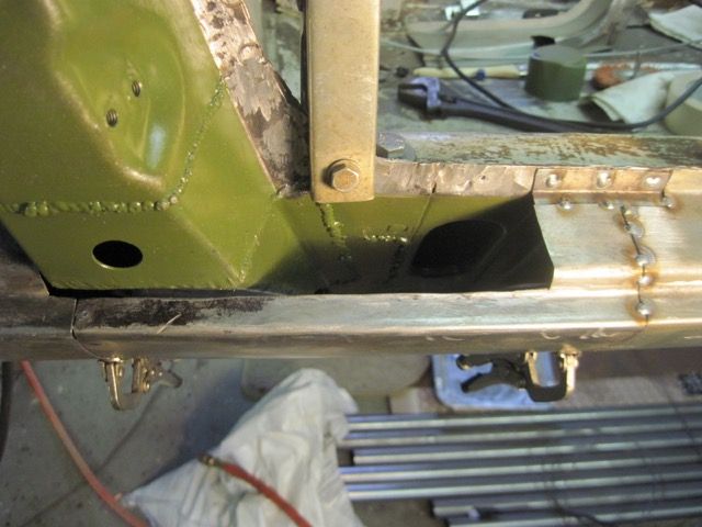
This is kind of strange, how this is put together. The light gauge inner panel must have been welded to the heavier outer stamping, then the subassembly welded to the frame rail. The outside panel of the frame rail is rusted and has to be replaced, but I have to cut away the inner panel just to get at the top welds. Not an issue in this case, since the inner panel is rusted also. If the inner panel were undamaged, I would still have to cut it away to fix this.
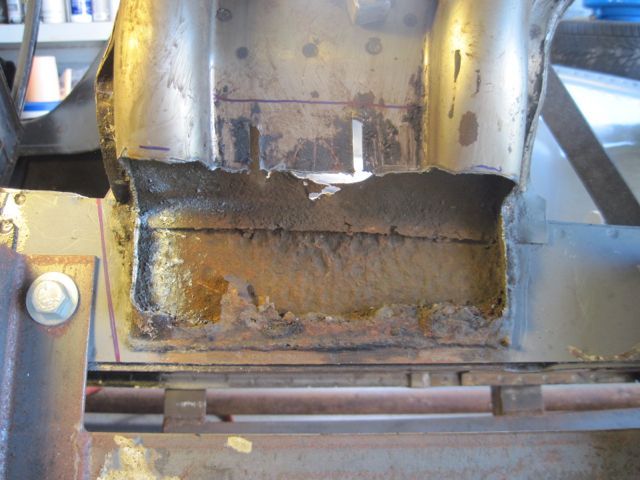
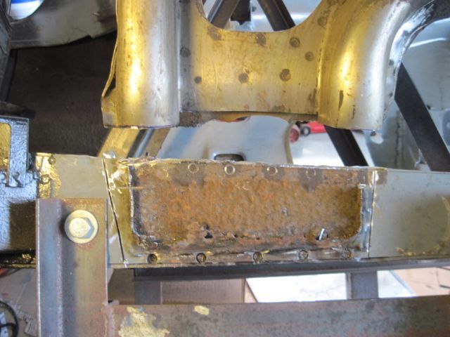
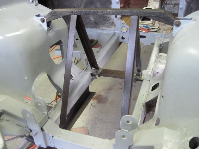
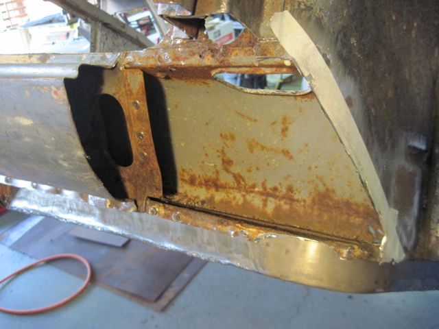
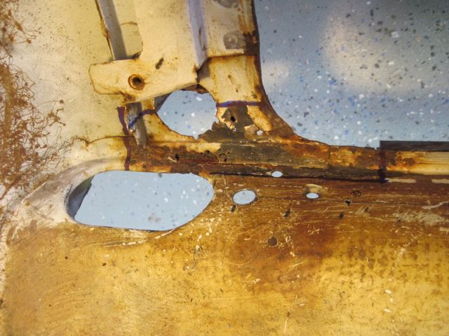
Before I start cutting this all apart, I made an “A” frame support to keep the rear end pieces in position. It connects the rear most suspension points to the bay brace, and to the fixed cross member just above the forward mounting points. I thought I had a better picture of it, and I’ll put one up later if I can find it.
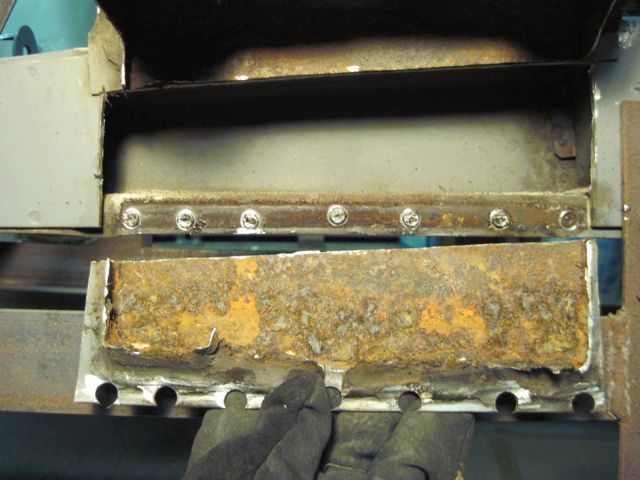
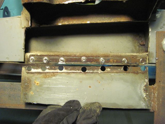
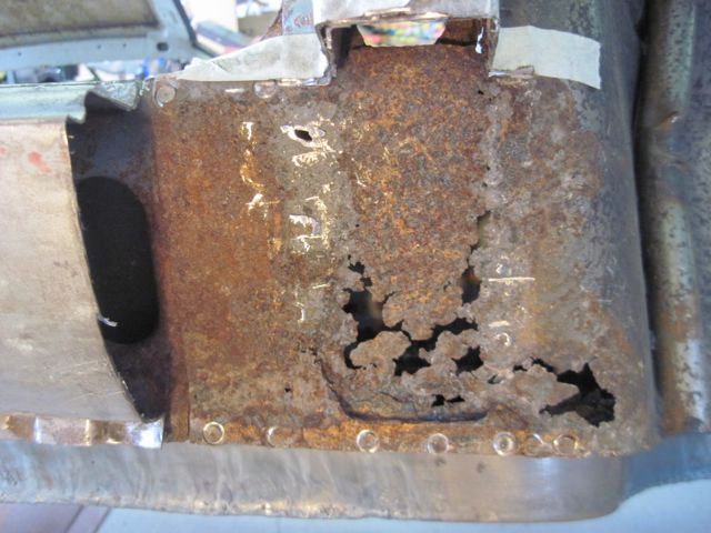
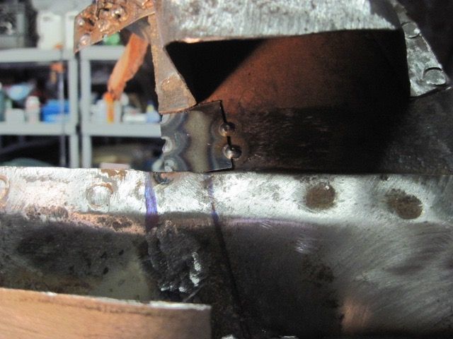
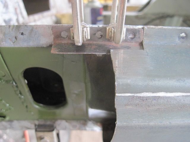
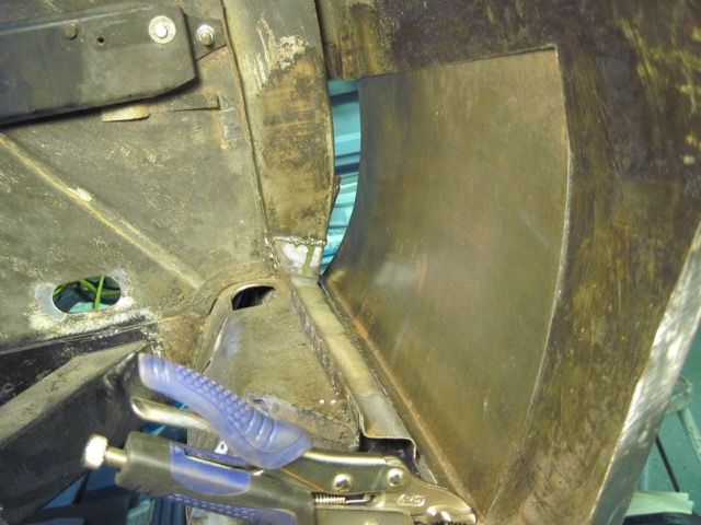
Here you can see part of it, while I prepare to cut off the inner panel just below the obround hole:
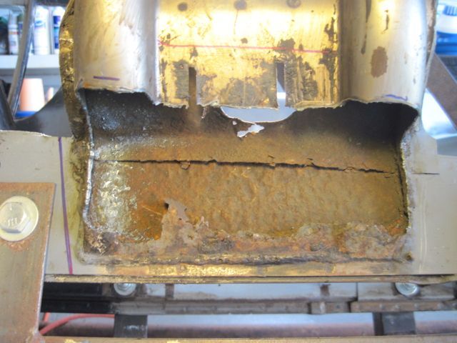
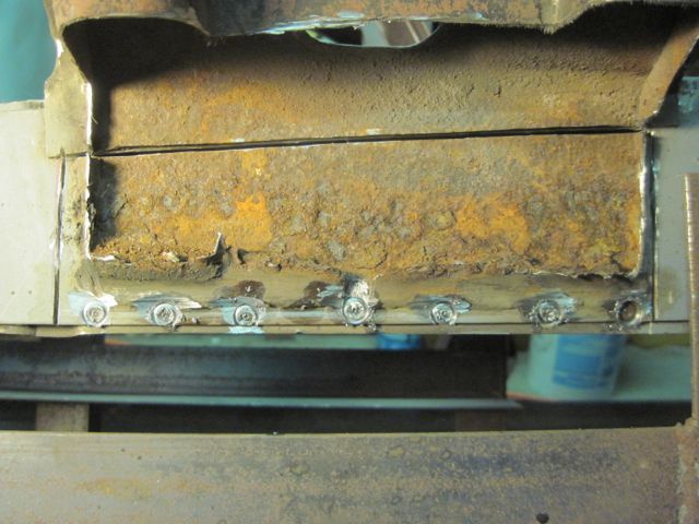
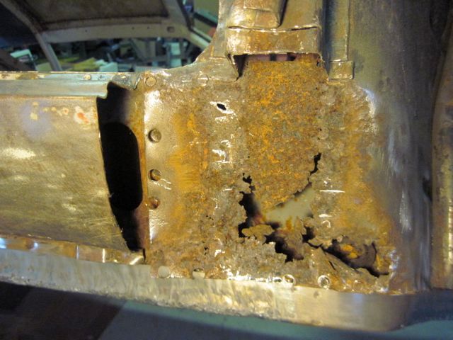
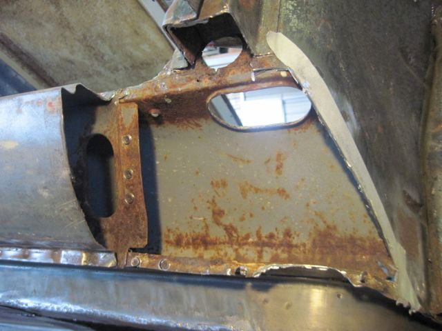
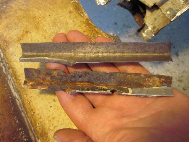
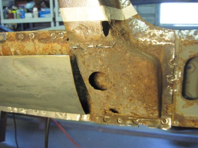
With that out of the way, I can cut the spot welds and slice the outer frame rail panel to cut out the rusty section and the old welds all at once. I used a cutting wheel for this, since I don’t know for sure what is inside:
I also cut the wheelhouse again, up higher, because the rust damage went up farther than I thought. Using the cutting wheel gives me a clean straight edge to work with:
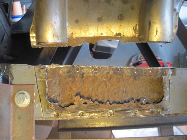
Finally it comes off:
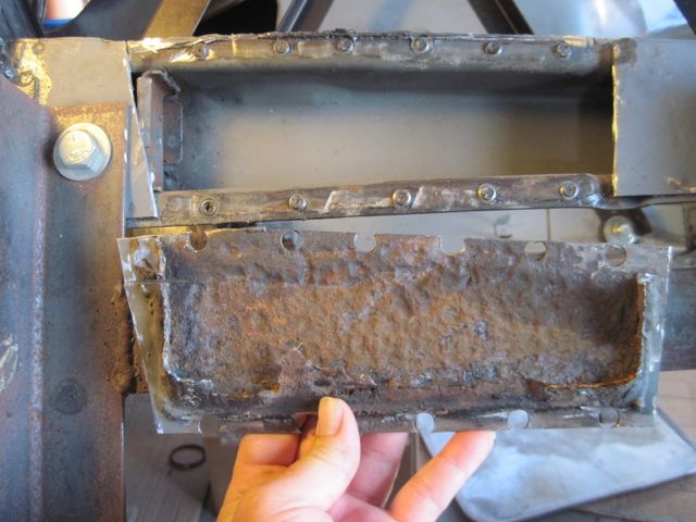
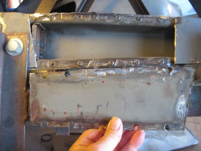
Thankfully, clean and nearly rust free on the inside:
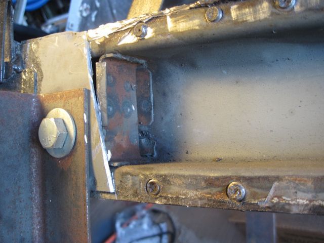
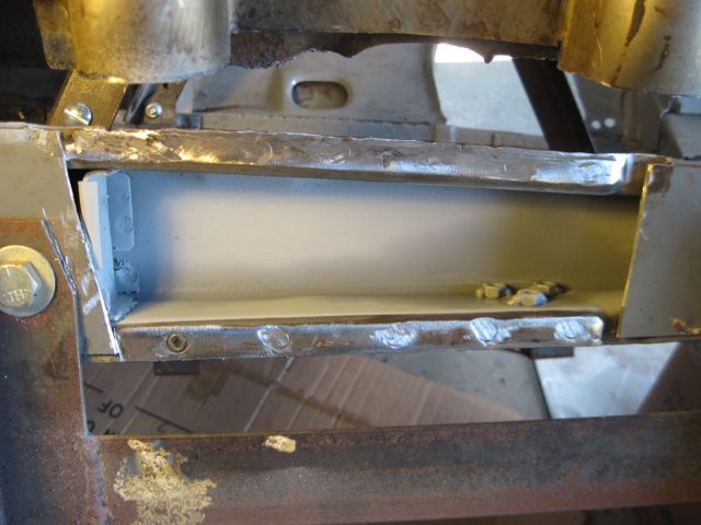
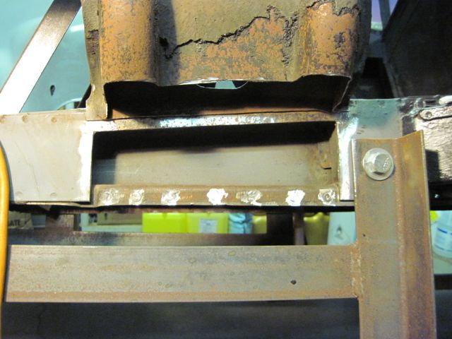
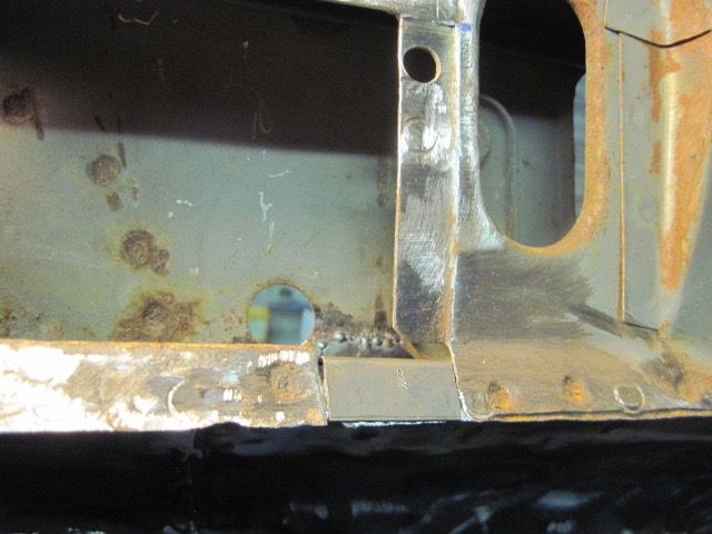
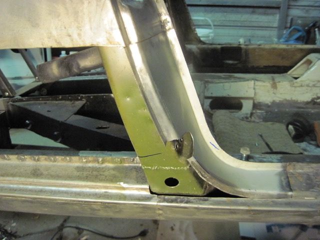
Here is the frame stiffener inside, next to the mount points. This is why I don’t use the plasma cutter when I don’t know what is in there; I could have destroyed this piece:
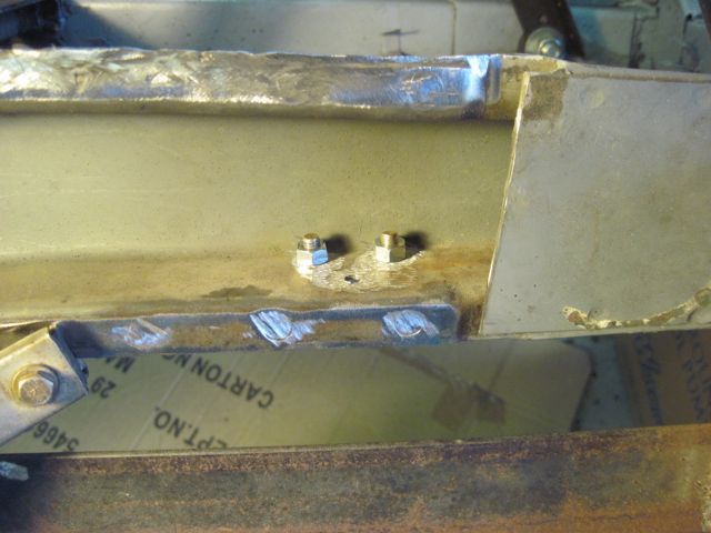
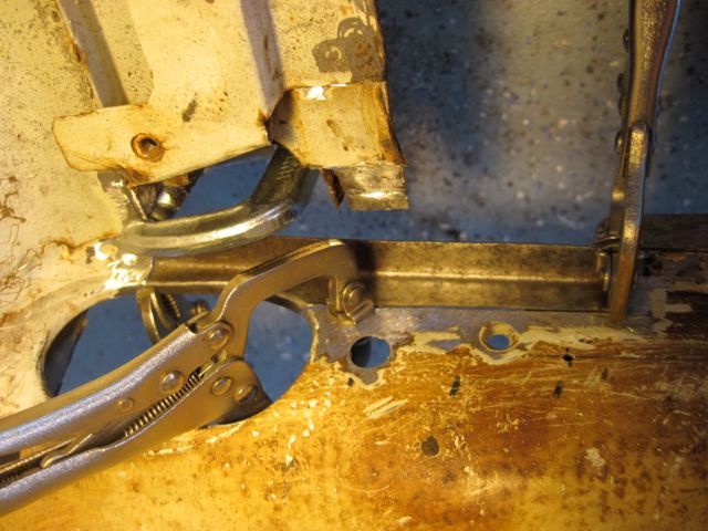
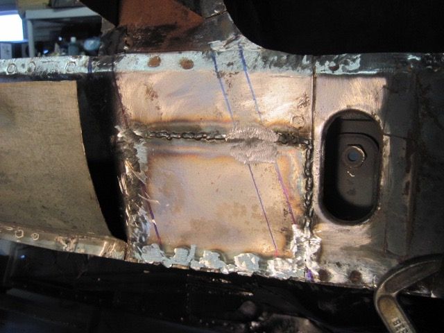
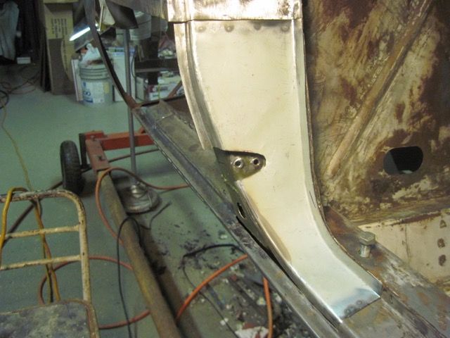
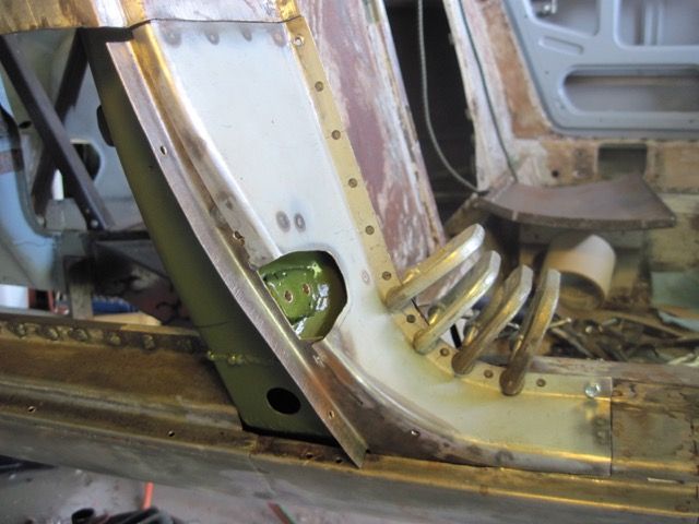
I decided to move my emergency brake assembly rearward, to make the cables shorter. This is where it ended up, and I’m welding some nuts on the inside to make for a stronger mount. If you stay with the stock arrangement, you do not have to do this:
With the area cleaned up, I spray in some zinc primer:
Next episode, I’ll dig into making the repair pieces.


I used the plasma cutter here, since I could see this was trashed pretty much through and through. A little collateral damage is no big deal.


This is kind of strange, how this is put together. The light gauge inner panel must have been welded to the heavier outer stamping, then the subassembly welded to the frame rail. The outside panel of the frame rail is rusted and has to be replaced, but I have to cut away the inner panel just to get at the top welds. Not an issue in this case, since the inner panel is rusted also. If the inner panel were undamaged, I would still have to cut it away to fix this.
Before I start cutting this all apart, I made an “A” frame support to keep the rear end pieces in position. It connects the rear most suspension points to the bay brace, and to the fixed cross member just above the forward mounting points. I thought I had a better picture of it, and I’ll put one up later if I can find it.
Here you can see part of it, while I prepare to cut off the inner panel just below the obround hole:

With that out of the way, I can cut the spot welds and slice the outer frame rail panel to cut out the rusty section and the old welds all at once. I used a cutting wheel for this, since I don’t know for sure what is inside:

I also cut the wheelhouse again, up higher, because the rust damage went up farther than I thought. Using the cutting wheel gives me a clean straight edge to work with:


Finally it comes off:


Thankfully, clean and nearly rust free on the inside:

Here is the frame stiffener inside, next to the mount points. This is why I don’t use the plasma cutter when I don’t know what is in there; I could have destroyed this piece:

I decided to move my emergency brake assembly rearward, to make the cables shorter. This is where it ended up, and I’m welding some nuts on the inside to make for a stronger mount. If you stay with the stock arrangement, you do not have to do this:

With the area cleaned up, I spray in some zinc primer:

Next episode, I’ll dig into making the repair pieces.
Here, I found the pics I was looking for.
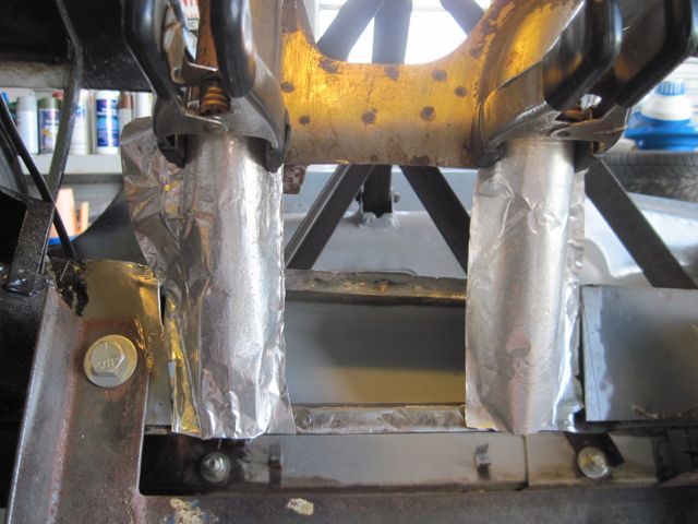
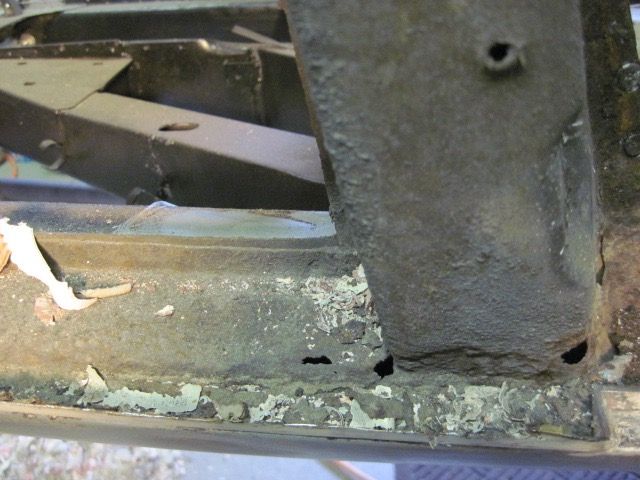
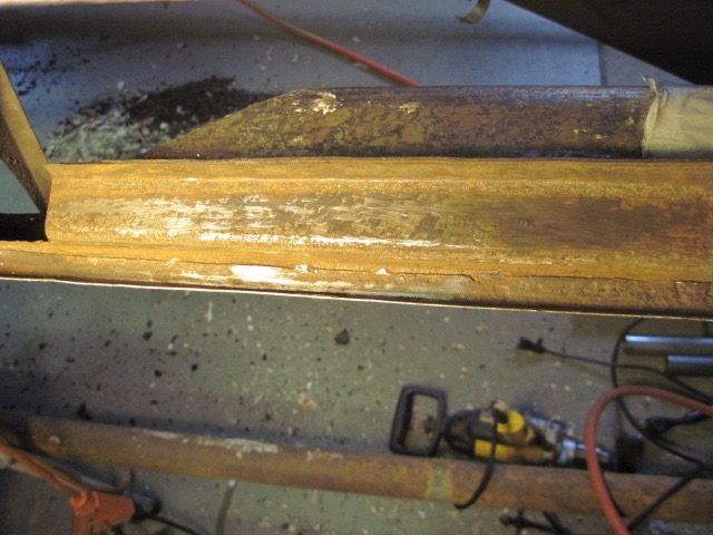
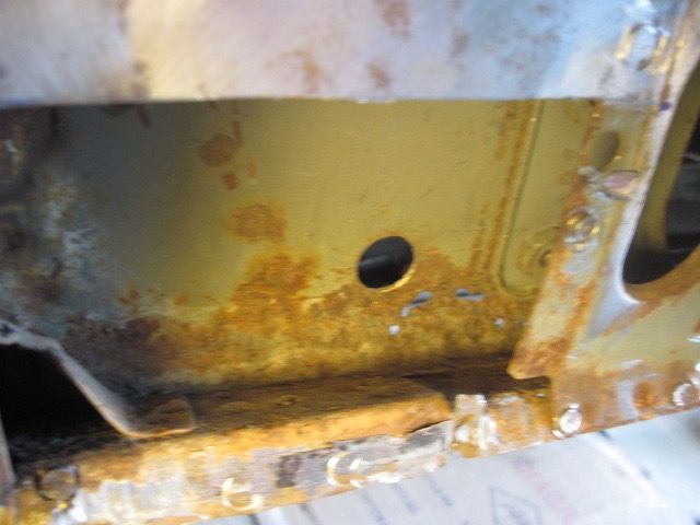
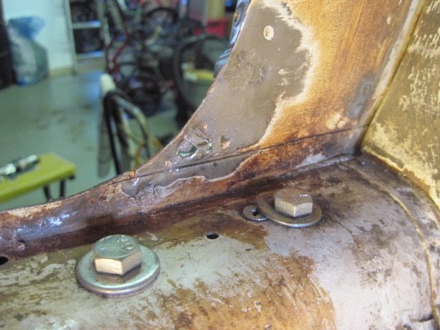
First are a couple I took while taking the rear suspension off. The undercoating hides the extent of the rust damage:
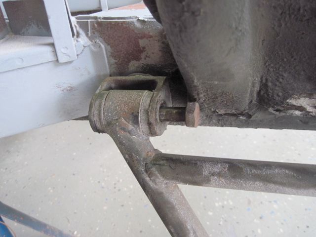
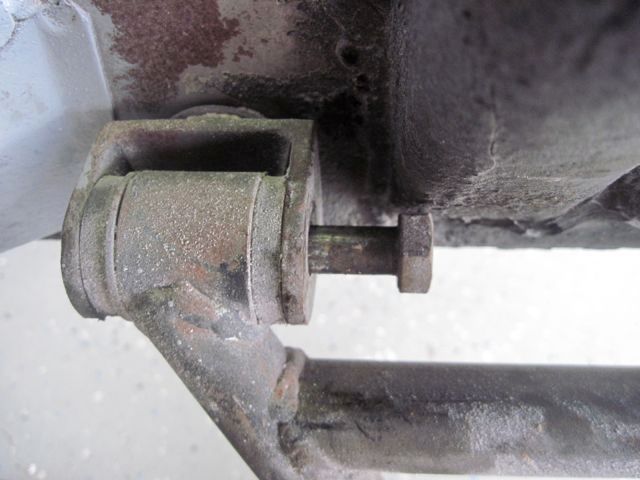
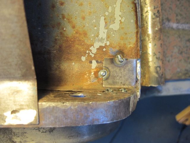
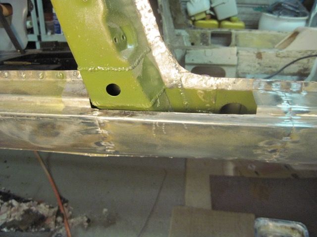
That is not why I took the photos. See how little clearance there is for that bolt head? It cannot be put in the other way, because the motor mount structure is there. I must be sure to leave enough clearance to get this bolt in and out, when I rebuild this part.
Here is the brace I made to hold the rear end pieces in position while I do the repairs:
First are a couple I took while taking the rear suspension off. The undercoating hides the extent of the rust damage:


That is not why I took the photos. See how little clearance there is for that bolt head? It cannot be put in the other way, because the motor mount structure is there. I must be sure to leave enough clearance to get this bolt in and out, when I rebuild this part.
Here is the brace I made to hold the rear end pieces in position while I do the repairs:

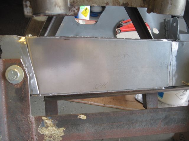
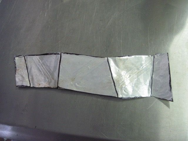
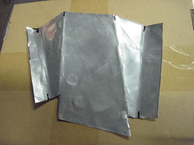
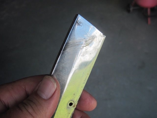
This pic shows a technique I came up with to make models of complex pieces. On simple pieces, cardboard and / or tape works ok; I often use breakfast cereal boxes. On curved pieces it does not conform easily nor hold the shape. I tried aluminum foil, but it is too delicate. This is aluminum too, but heavier. I save “disposable” cooking pans from the kitchen, clean them out, and cut out the bottom of the pan. After smoothing and flattening the material, it works great for mocking up parts like this.
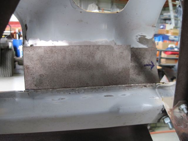
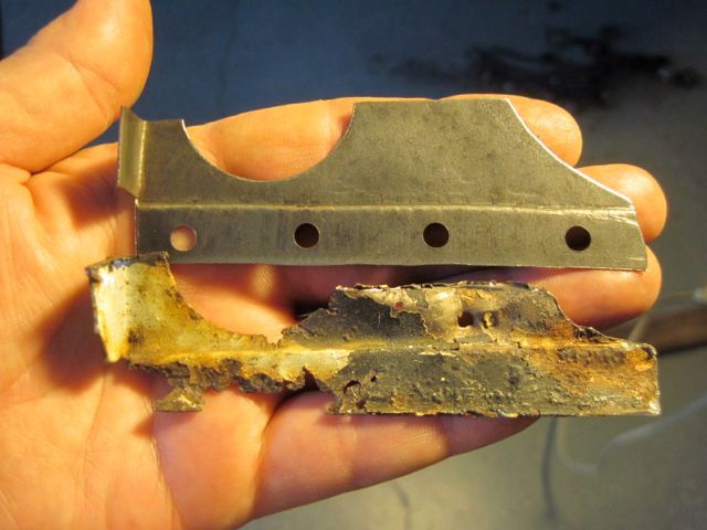
Earlier, JT asked me about the gauge of steel needed. This is one of the 18 gauge pieces I had to order. I could have used 16 I suppose, but it would have made for some uneven steps I had to weld across. Probably not too important, but thought you would like to know.
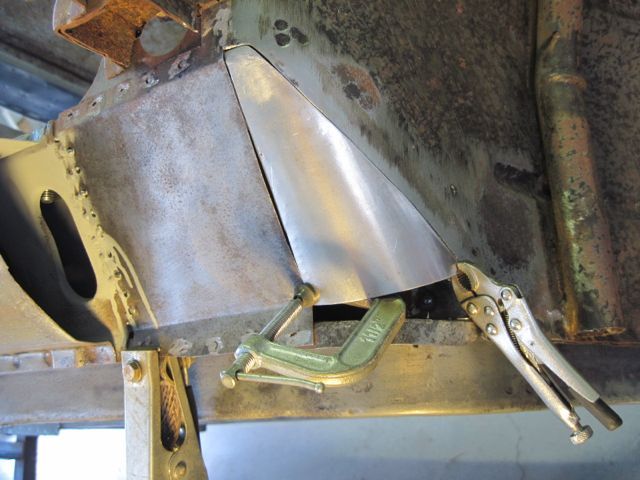
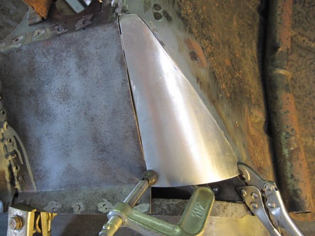
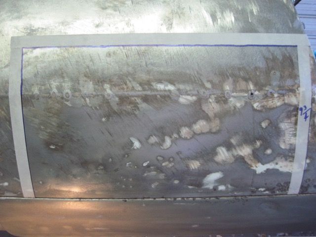
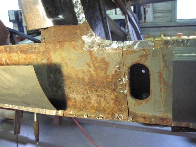
I had to cut away the inner wheelhouse panel here, which left me with a choice; do I reproduce the obround hole, or eliminate it. I decided to eliminate it. The rear most part of this panel is nearly flat, but the front part is concave, so I made it in two pieces:
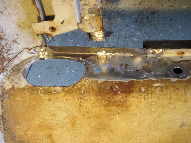
Here I have cleaned up the weld zones, added a hole to allow rust proofing to be put in, and sprayed in some zinc primer:
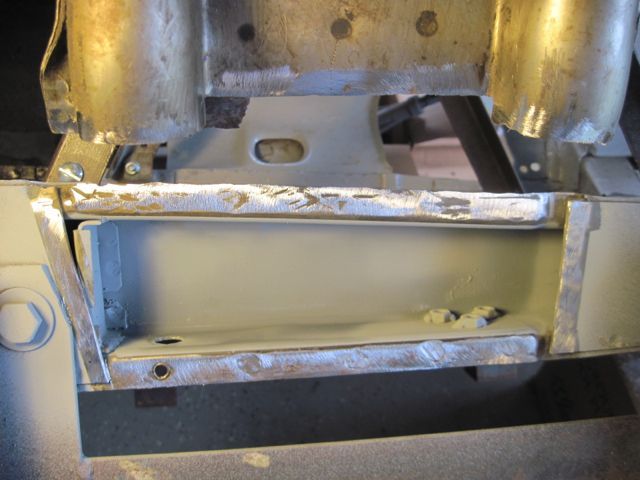
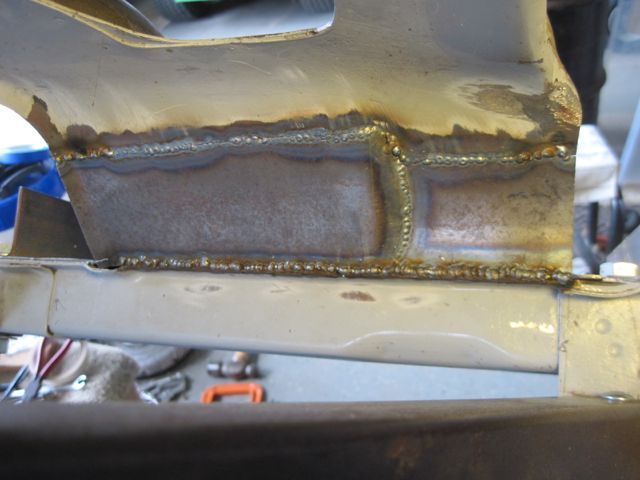
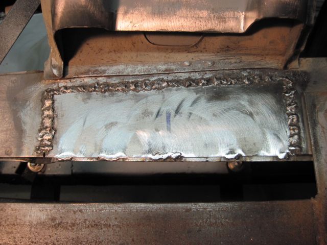
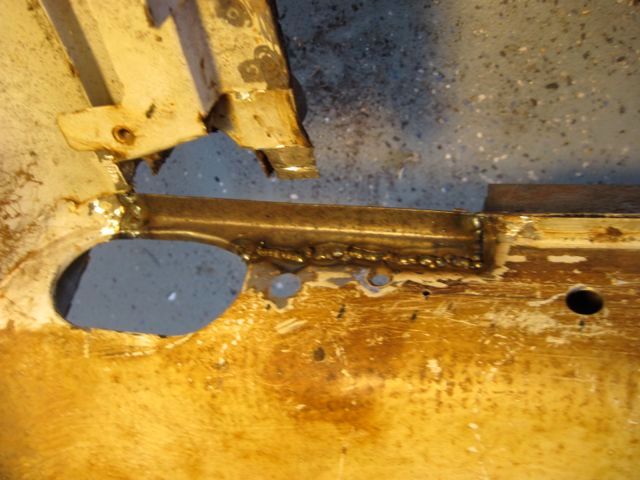
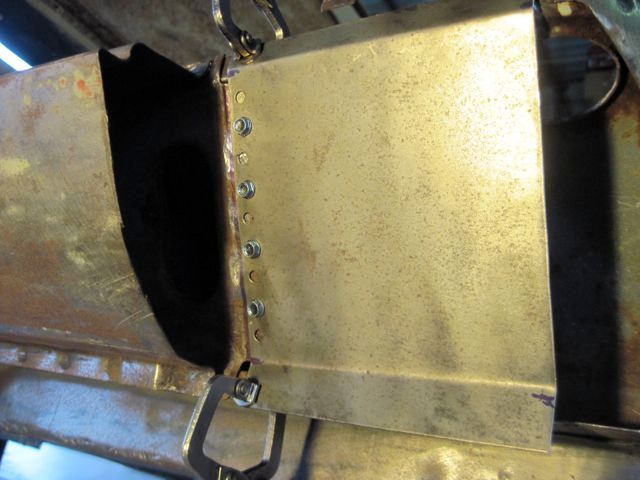
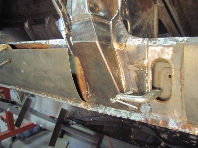
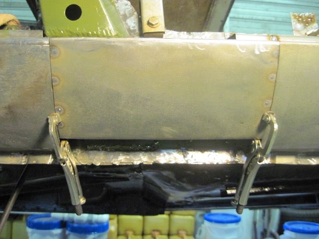
On this frame rail repair piece, I decided to scallop the top to make places to weld. I just wanted less post weld clean up to do, since I have more pieces to weld in this same area:
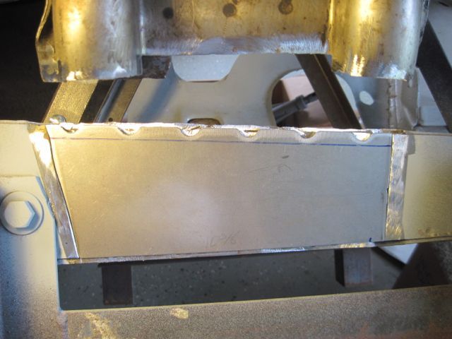
Now tacked in place:
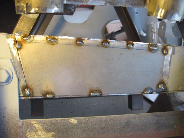
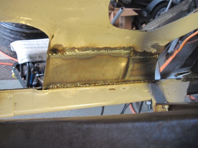
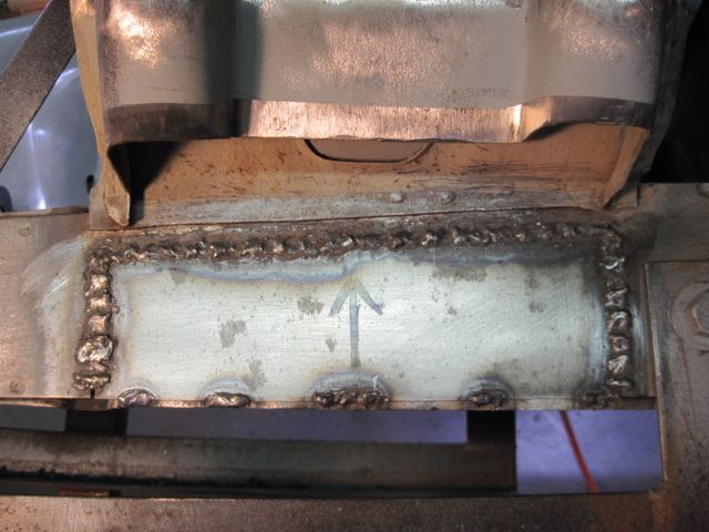
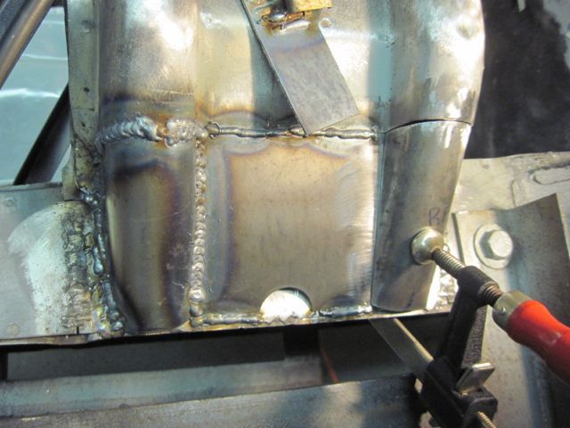
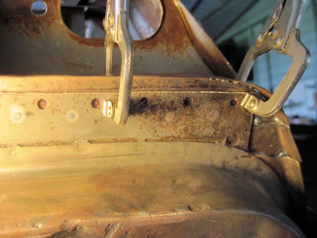
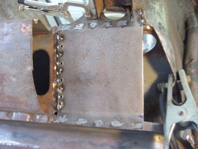
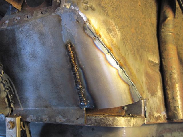
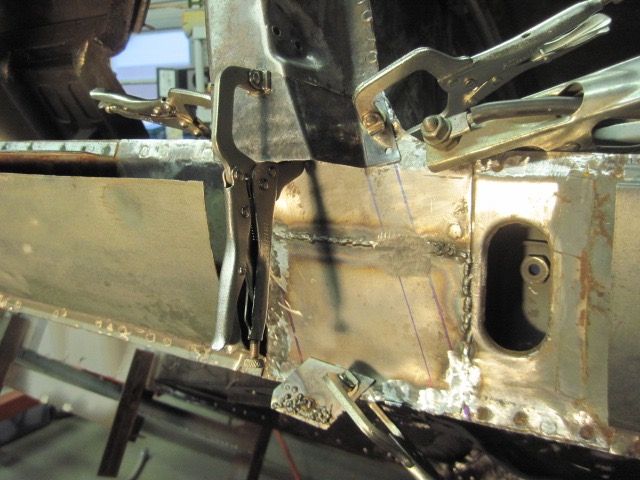
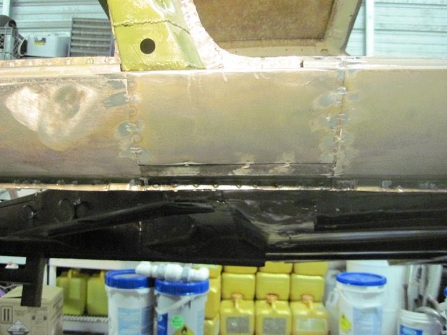
Here I am starting to weld in the inner panel repairs. This is 22 gauge, and I am welding it from the inside so it looks better on the visible side:
I had to weld from this side down where it joins the frame rail, but the upper seam came out quite nice:
Now to mask off the weld zones, and spray some primer in there:
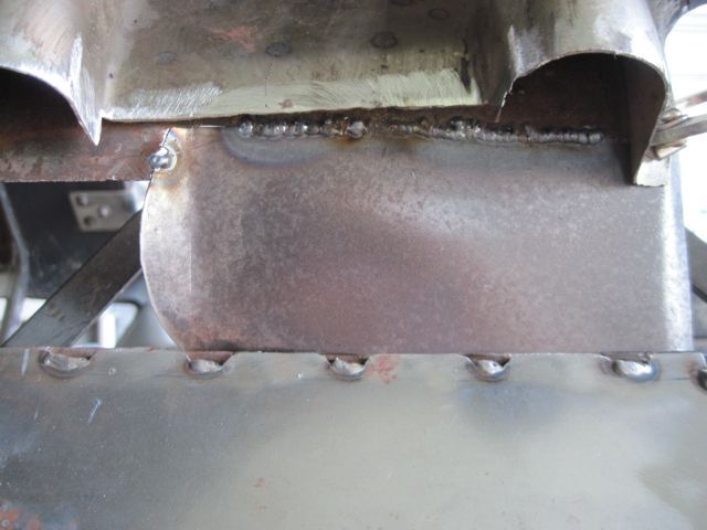
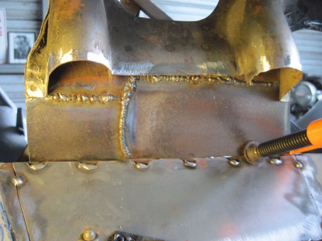
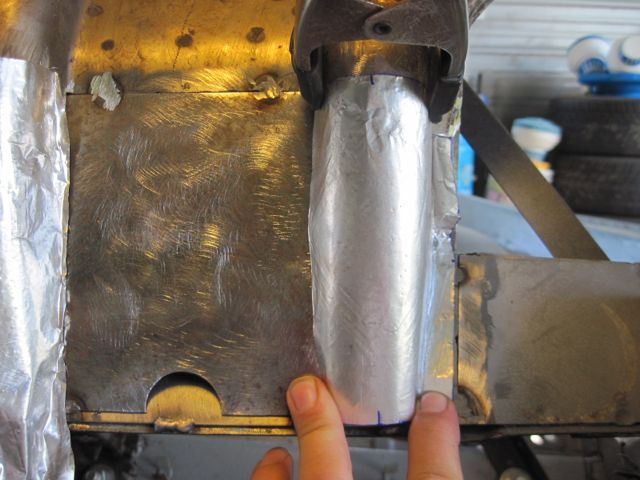
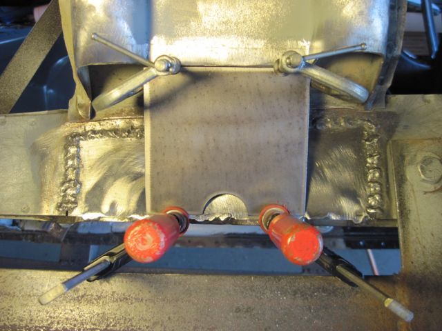
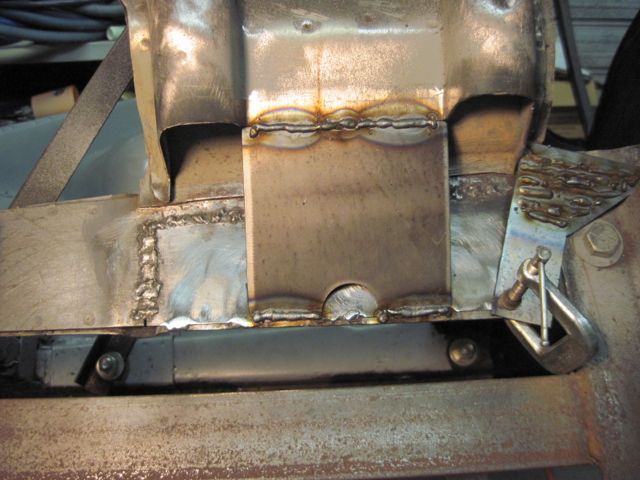
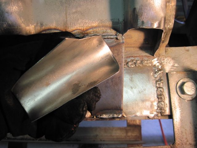
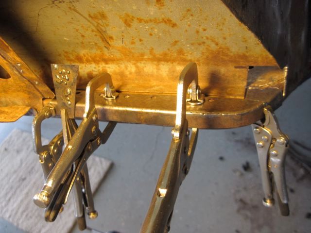
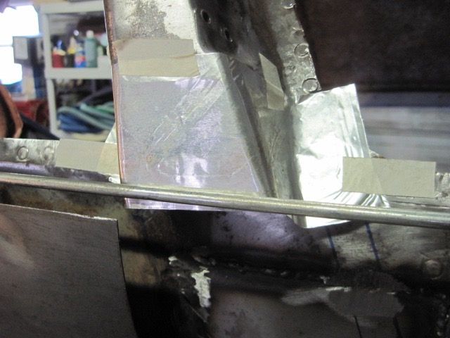
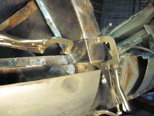
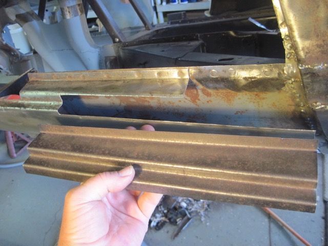
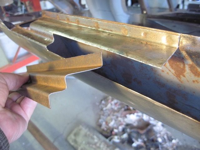
I decided to make the structural repair in 3 pieces. With the simple workshop tools I have, it is just too hard to make all of these bends and get them just right. This is 16 gauge steel, and I have already tacked in the flat center piece:
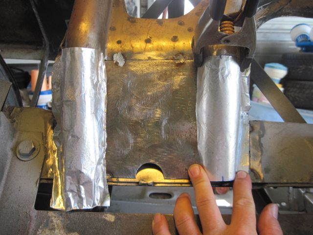
This is my first try at this. Getting it round at the top and kind of rectangular at the bottom was a PAIN.
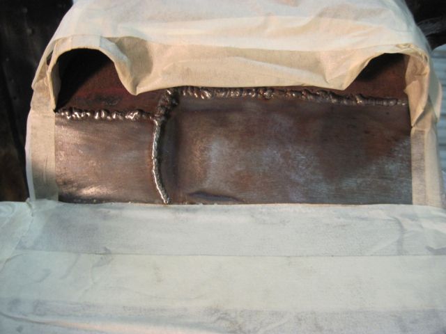
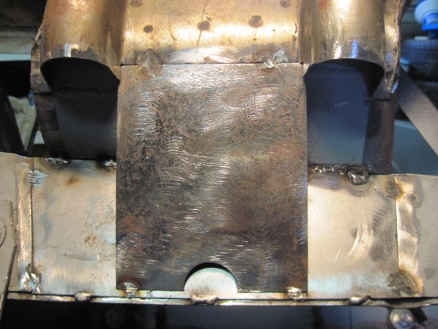
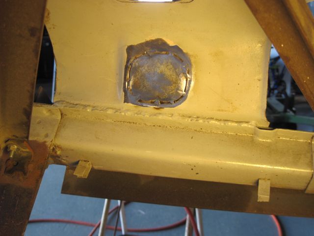
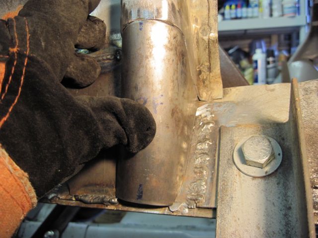
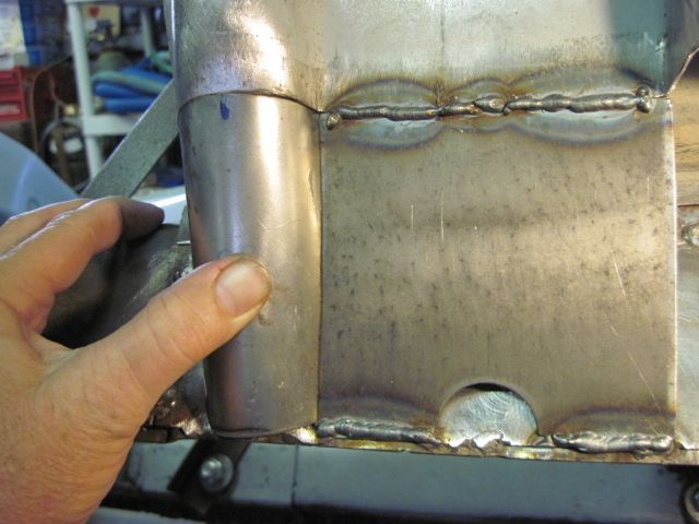
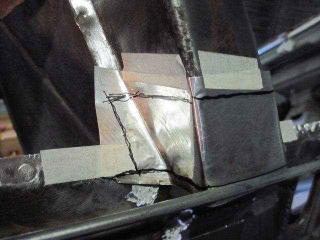
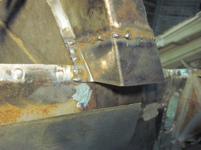
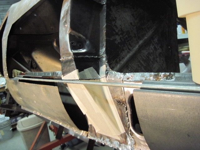
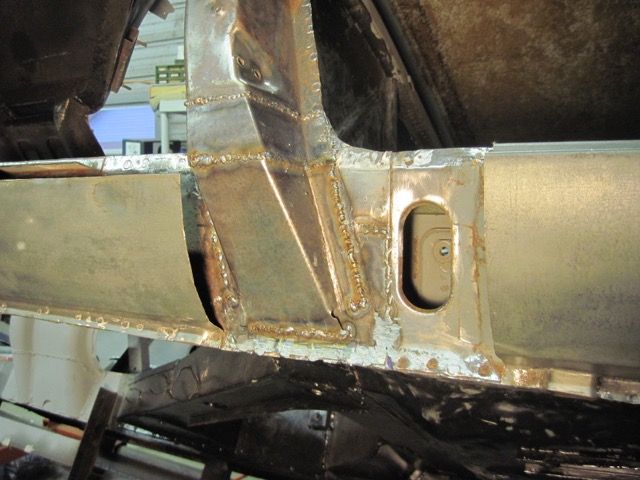
I decided to do away with the side flanges; I just could not get them right. I “T” welded the pieces instead. Here it is just about done with welding:
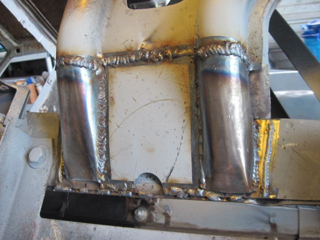
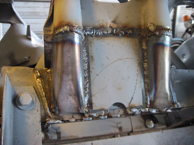
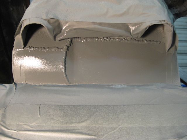
And after several coats of zinc primer, I’ll declare victory and move on:
Not sure what I will go after next; tune in again to find out!

Earlier, JT asked me about the gauge of steel needed. This is one of the 18 gauge pieces I had to order. I could have used 16 I suppose, but it would have made for some uneven steps I had to weld across. Probably not too important, but thought you would like to know.

I had to cut away the inner wheelhouse panel here, which left me with a choice; do I reproduce the obround hole, or eliminate it. I decided to eliminate it. The rear most part of this panel is nearly flat, but the front part is concave, so I made it in two pieces:

Here I have cleaned up the weld zones, added a hole to allow rust proofing to be put in, and sprayed in some zinc primer:

On this frame rail repair piece, I decided to scallop the top to make places to weld. I just wanted less post weld clean up to do, since I have more pieces to weld in this same area:

Now tacked in place:

Here I am starting to weld in the inner panel repairs. This is 22 gauge, and I am welding it from the inside so it looks better on the visible side:


I had to weld from this side down where it joins the frame rail, but the upper seam came out quite nice:


Now to mask off the weld zones, and spray some primer in there:


I decided to make the structural repair in 3 pieces. With the simple workshop tools I have, it is just too hard to make all of these bends and get them just right. This is 16 gauge steel, and I have already tacked in the flat center piece:


This is my first try at this. Getting it round at the top and kind of rectangular at the bottom was a PAIN.


I decided to do away with the side flanges; I just could not get them right. I “T” welded the pieces instead. Here it is just about done with welding:


And after several coats of zinc primer, I’ll declare victory and move on:

Not sure what I will go after next; tune in again to find out!
Best thread on the forum! Great progress!
Thanks Garth. Did you get your block fixed after it inhaled the air cleaner screw?
It seems that photo bucket has messed up my pic links. Dang, as if I don't have enough stuff to fix.
It seems that photo bucket has messed up my pic links. Dang, as if I don't have enough stuff to fix.
It seems like it's back now.
It had messed with everyone....
PS - Did you see how Peter Fenlon had built his uprights? He and his "tinbender" did a great job...
Scroll Down for #3840 Upright Repair
It had messed with everyone....
PS - Did you see how Peter Fenlon had built his uprights? He and his "tinbender" did a great job...
Scroll Down for #3840 Upright Repair
No, I had not seen Peter's work. He did a great job. Wish I had thought of that. I also have to fix the rear crossmember, bent from jacking.
Photos seem to be linking correctly now, but I still have hundreds of error messages from photo bucket; they look like sticky notes on the background of my browser display, making it hard to read anything other than the thread.
It's late and I have to get to bed, work tomorrow. Hope this will be cleared up by then.
It seems the photo bucket problem is resolved. That had me worried; no way I wanted to try to re-link all these photos with the text. I have learned a trick, though. To post this stuff up, I first choose the pics I want to use, then export them and upload to photo bucket. Then, I open a simple text file, write the copy I want with the pics, and put the links from photo bucket into my text file and save it on my machine. Then I just copy and paste the whole works at once into the forum entry window. That way, if it ever gets messed up, I can just pull up my text file, and I have all the information right there.
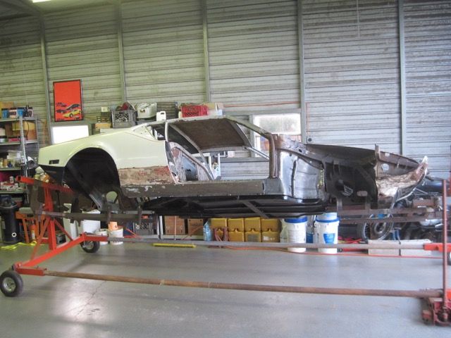
So on with the show. Here are just a few pics of the overall progress. Just to recap, I started with the deck lid and trunk lid. The metal work is done on them and they are in primer, wrapped in plastic and stored away. Then I cleaned up the engine bay and painted it. I removed the doors and dismantled all of the glass, trim and so on. The doors were so badly rusted I bought a set. Meanwhile, I pulled the fixed glass, and did the metal repairs around them as far as I could. The new doors arrived, and I stripped and repaired them as needed, painted, and test fitted all the mechanisms to make sure I had no surprises waiting there. They too are wrapped up and stored away. Next I repaired the floor pans, which had both rust and jacking damage. Then I worked my way down the driver’s side, front to back, repairing all of the rust damage. There is very little accident damage on this side of the car.
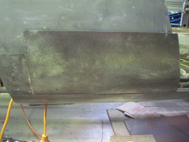
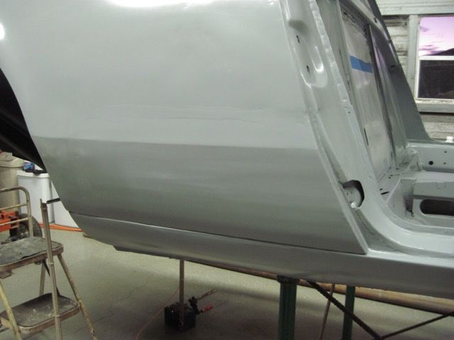
At this point, I cleaned up what I had done so far, and rolled it outside for primer, as you see here:
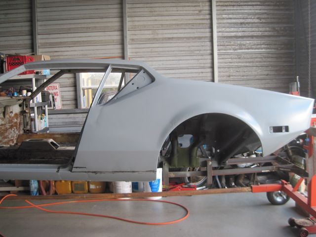
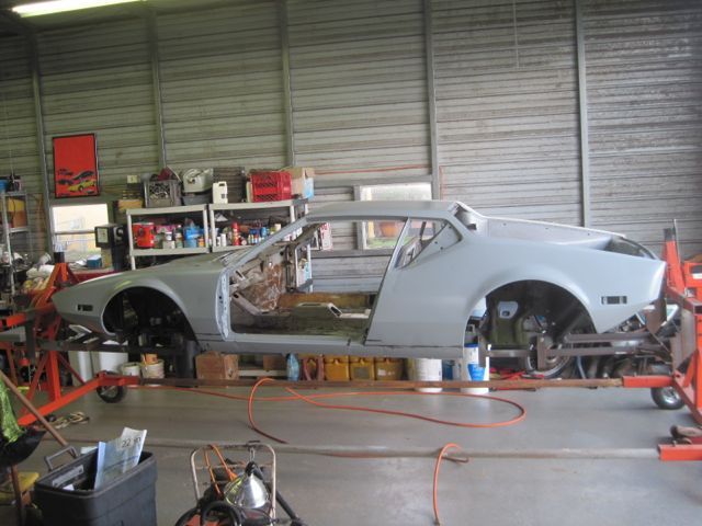
You can see I’ve already put some epoxy into the body seams where I need to contour them to make them uniform again. I won’t mess with it anymore until I am ready to do the second coat of primer over the whole thing. I have a few minor wrinkles to fix around the rear wheel arch, but for the most part, I’m about done with this side.
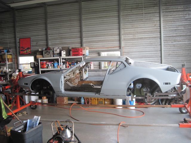
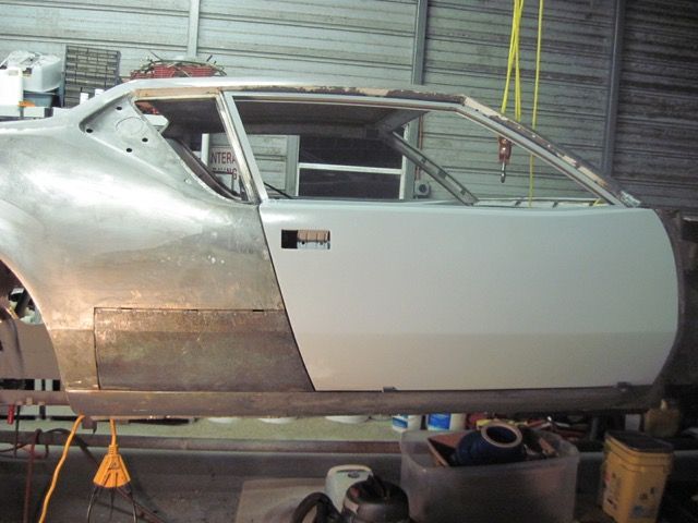
This side needs a bit of work yet:
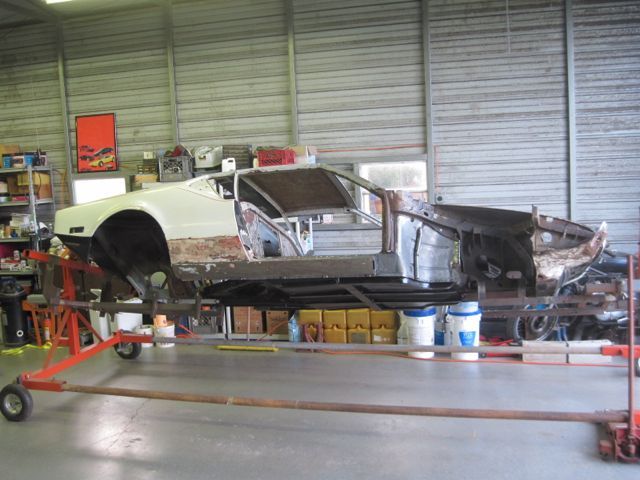
When I work my way up this side, from rear to front this time, I’ll roll it outside and primer it again. Then I’ll take it off the rotisserie to do the front and rear repairs.
Stay tuned!
So on with the show. Here are just a few pics of the overall progress. Just to recap, I started with the deck lid and trunk lid. The metal work is done on them and they are in primer, wrapped in plastic and stored away. Then I cleaned up the engine bay and painted it. I removed the doors and dismantled all of the glass, trim and so on. The doors were so badly rusted I bought a set. Meanwhile, I pulled the fixed glass, and did the metal repairs around them as far as I could. The new doors arrived, and I stripped and repaired them as needed, painted, and test fitted all the mechanisms to make sure I had no surprises waiting there. They too are wrapped up and stored away. Next I repaired the floor pans, which had both rust and jacking damage. Then I worked my way down the driver’s side, front to back, repairing all of the rust damage. There is very little accident damage on this side of the car.
At this point, I cleaned up what I had done so far, and rolled it outside for primer, as you see here:


You can see I’ve already put some epoxy into the body seams where I need to contour them to make them uniform again. I won’t mess with it anymore until I am ready to do the second coat of primer over the whole thing. I have a few minor wrinkles to fix around the rear wheel arch, but for the most part, I’m about done with this side.
This side needs a bit of work yet:

When I work my way up this side, from rear to front this time, I’ll roll it outside and primer it again. Then I’ll take it off the rotisserie to do the front and rear repairs.
Stay tuned!
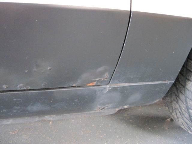
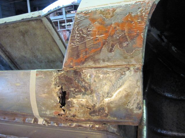
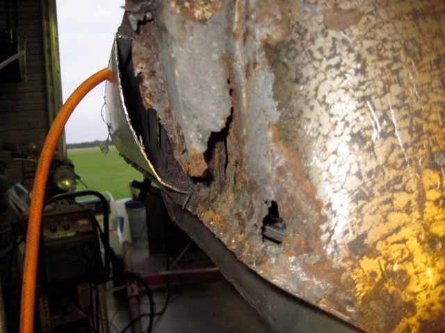
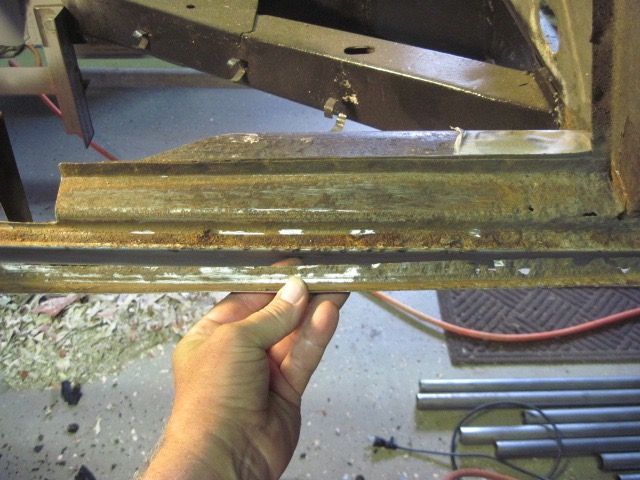
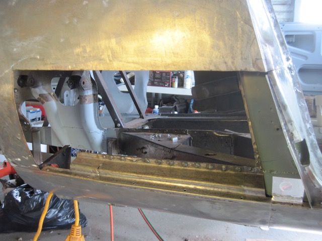
The right side repairs are almost the same as the left, so much the same work needs to be done. Stripping off the undercoat reveals the rust damage:
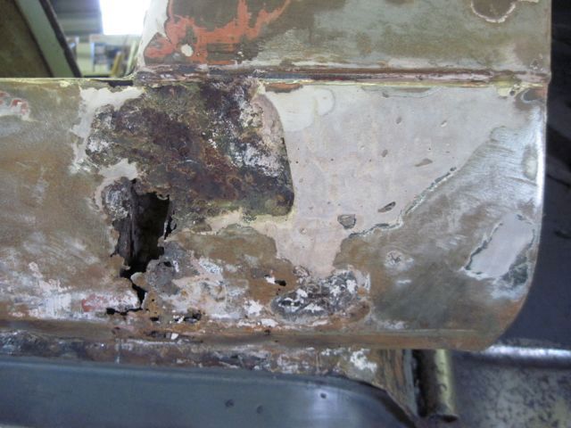
The inside is always worse:
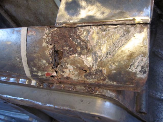
This side is not as bad as the left. I can see through the access hole that the damage on this side does not extend up so far:
This time I use the grinding disc to start, not the plasma cutter. Just to save myself from doing it twice, since I have a better idea about the extent of the damage that needs to be cut away:
Cutting the spot welds along the lower frame rail flange finally cuts this piece free:
Again, thankfully, very little rust on the inside:
Here I have trimmed away another 1/2 inch of the inner wheel house metal. Just to satisfy myself that there is only surface rust and scale between these pieces. Because of this, I do not have to cut the outer frame rail panel all the way to the top.
They are not welded together inside this structure, only on the engine bay side. This also gets the thin inner wheel house metal out of my way, so I can clean the frame rail pieces up for priming and welding:
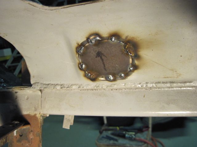
Now, however, I have a hole on the right side, and not on the left. The simple answer is to weld a cover over this one:
Next, the frame rail repair piece is welded in:
Now to rebuild the outer structure:
Almost done:
Ready to do the last few welds:
Next episode; I’ll go back in time (a bit) to fill in some gaps.

The inside is always worse:

This side is not as bad as the left. I can see through the access hole that the damage on this side does not extend up so far:

This time I use the grinding disc to start, not the plasma cutter. Just to save myself from doing it twice, since I have a better idea about the extent of the damage that needs to be cut away:


Cutting the spot welds along the lower frame rail flange finally cuts this piece free:

Again, thankfully, very little rust on the inside:

Here I have trimmed away another 1/2 inch of the inner wheel house metal. Just to satisfy myself that there is only surface rust and scale between these pieces. Because of this, I do not have to cut the outer frame rail panel all the way to the top.

They are not welded together inside this structure, only on the engine bay side. This also gets the thin inner wheel house metal out of my way, so I can clean the frame rail pieces up for priming and welding:


Now, however, I have a hole on the right side, and not on the left. The simple answer is to weld a cover over this one:


Next, the frame rail repair piece is welded in:


Now to rebuild the outer structure:


Almost done:


Ready to do the last few welds:

Next episode; I’ll go back in time (a bit) to fill in some gaps.
I got things a bit out of order. I actually did some of the right A pillar repairs along with the left. As they are more - or - less mirror images of each other, it seemed like a good idea to make some of the repair pieces at the same time.
Here is a look at the area before stripping it down:
It is amazing how much damage can be covered with bondo and paint. Scary:
No point in wasting time, taking the bondo off of a piece that obviously has to be thrown away and rebuilt from scratch:
I will toss it in the junk bucket and keep it till I’m done, however. Even a nasty scrap like this is helpful to recreate the contours in the replacement piece.
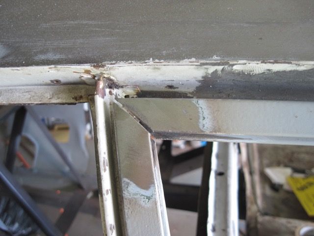
This is the lower front corner of the door frame, just below the hinge:
And here the inside view:
A shame the factory did not put a rock shield here. A simple piece of sheet metal would have made a big difference. You can be sure I’m going to put one in.
Starting to strip paint off the fender:
Cutting spot welds and sectioning the pieces to be cut apart:
The forward most piece of the outer rocker is cut free:
Revealing more nastyness:
Heating bondo and putty with a propane torch will soften it up, but be careful; it will burn if you get it hot enough:
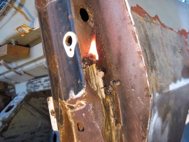
There was a lot of bondo in here, covering up a slightly bent A pillar. I think this contour panel was replaced. I can’t see how you could bend the A pillar without destroying it. I’ll be looking closely at this area when I get to fitting the new doors:
Just like on the driver’s side, the bottom of this A pillar has to be cut off:
Rust never sleeps:

Starting to cut away the wheel well surround from the mid rocker and floor pan. Now having had the other side apart, I know where the lap seam is:
I had to cut another 1/2 inch off the bottom of the A pillar to get at the rusty metal under it. The tape is my guide for cutting away the damaged section:
And off it comes:
This car has rust in some bizarre places; this just below the fuse box mount:
Most of the de-construction is done here, so next time I’ll start to detail some of the re-construction. Stay tuned!
Here is a look at the area before stripping it down:

It is amazing how much damage can be covered with bondo and paint. Scary:

No point in wasting time, taking the bondo off of a piece that obviously has to be thrown away and rebuilt from scratch:

I will toss it in the junk bucket and keep it till I’m done, however. Even a nasty scrap like this is helpful to recreate the contours in the replacement piece.
This is the lower front corner of the door frame, just below the hinge:

And here the inside view:

A shame the factory did not put a rock shield here. A simple piece of sheet metal would have made a big difference. You can be sure I’m going to put one in.
Starting to strip paint off the fender:

Cutting spot welds and sectioning the pieces to be cut apart:

The forward most piece of the outer rocker is cut free:

Revealing more nastyness:


Heating bondo and putty with a propane torch will soften it up, but be careful; it will burn if you get it hot enough:

There was a lot of bondo in here, covering up a slightly bent A pillar. I think this contour panel was replaced. I can’t see how you could bend the A pillar without destroying it. I’ll be looking closely at this area when I get to fitting the new doors:

Just like on the driver’s side, the bottom of this A pillar has to be cut off:

Rust never sleeps:


Starting to cut away the wheel well surround from the mid rocker and floor pan. Now having had the other side apart, I know where the lap seam is:

I had to cut another 1/2 inch off the bottom of the A pillar to get at the rusty metal under it. The tape is my guide for cutting away the damaged section:


And off it comes:


This car has rust in some bizarre places; this just below the fuse box mount:

Most of the de-construction is done here, so next time I’ll start to detail some of the re-construction. Stay tuned!
I’ll start by sectioning out this rusty bit below the fuse box bracket:
Rough cut on the repair piece:
After some shaping:
Clamping in place to weld:
Raw welding work:
And after some smoothing:
View from the inside:
I decided to try a different approach to the floorpan corner where it curves in to meet the wheel well:
Here is the section that needs to come off; rusty and pretty beat up:
I will overlap the repair piece with the good metal that remains:
Test fitting:
A gap needs to be filled here:
Remember I said the little pieces can be the hardest to do. It took me 4 tries to get this little bugger right:
Next comes the bottom of the A pillar’s inner panel. I used a hole saw in this piece:
Then cut and flanged it to match the mating pieces:
This portion of the wheel well surround, where it joins the mid-rocker, is pretty straight forward. The screws are only there because I can’t get a clamp that far back to hold them together:
Now to start welding:
One more little patch, and a drain / access hole, while I can still get at this area:
Here I’m just checking all clear, before I put in my roll cage reinforcement:
Now to patch in this contoured piece of the wheel well surround:
These kind of pieces are a bear to get fitted just right:
Finally time to weld:
Not sure why I do not have any pics of finishing this area. I will take some if I need, to finish this part.

Rough cut on the repair piece:

After some shaping:

Clamping in place to weld:

Raw welding work:

And after some smoothing:

View from the inside:

I decided to try a different approach to the floorpan corner where it curves in to meet the wheel well:


Here is the section that needs to come off; rusty and pretty beat up:

I will overlap the repair piece with the good metal that remains:

Test fitting:

A gap needs to be filled here:

Remember I said the little pieces can be the hardest to do. It took me 4 tries to get this little bugger right:

Next comes the bottom of the A pillar’s inner panel. I used a hole saw in this piece:

Then cut and flanged it to match the mating pieces:

This portion of the wheel well surround, where it joins the mid-rocker, is pretty straight forward. The screws are only there because I can’t get a clamp that far back to hold them together:

Now to start welding:


One more little patch, and a drain / access hole, while I can still get at this area:

Here I’m just checking all clear, before I put in my roll cage reinforcement:

Now to patch in this contoured piece of the wheel well surround:

These kind of pieces are a bear to get fitted just right:

Finally time to weld:

Not sure why I do not have any pics of finishing this area. I will take some if I need, to finish this part.
quote:Thanks Garth. Did you get your block fixed after it inhaled the air cleaner screw?
Nope! It's still with the machinist. They may have sleeved the #8 cylinder already, but informed me the piston was collapsed and needed to be replaced. Only problem, Probe no longer makes pistons! Since this is a stroker engine, I couldn't just purchase any other piston to replace the damaged one, so I started looking at the stroker piston offerings from other manufacturers - was getting crazy quotes of $1,000 and up for 383 stroker pistons, but only available .030 over, which means I would have to bore my block again to punch it out from .020 to .030. So I began searching the country for a set of .020 over Probe SRS forged stroker pistons for a 351C and found a set on the East Coast. Had to buy the whole set, but it was half the cost of any others I got quotes for, and I don't need to punch out my block any further. They should arrive next week.
Thanks for asking. Now, back to your amazing work!
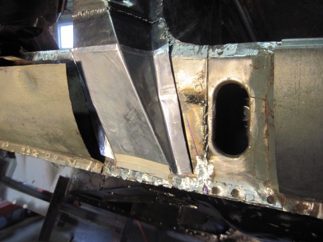
Just to finish my previous episode, here is the area completed. Welded in the last wedge shaped piece, ground the welds smooth, and wiped down with ospho to stop surface rust.

I really appreciate all of the great comments and feedback on this thread so far. Someone suggested that it would be a good time to start fitting the doors before I get too far along. Seemed like a good idea at the time; but that’s why I haven’t posted anything for a month. Dang what a can of worms!
I’m not done yet, but I have a solution to a difficult problem that I thought I would share with you.
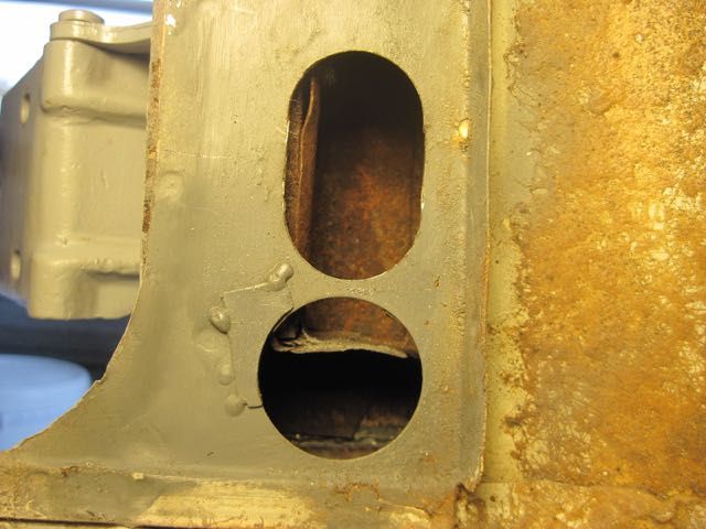
Anyone who has done this already, knows what a pain it is to get the door in just the right position, then get the hinge bolts tightened up without moving the door. It’s not just a pain, it’s impossible. It’s not the bolts that hold the hinge to the door, those are easy. The flat head, countersunk screws that hold the hinge to the A pillar, cannot be tightened with the door in the closed position. They must be loose enough to allow the door to be jockeyed into position, then you open the door enough to tighten the screws, the door slips, and you start over. Again. And again. And again.
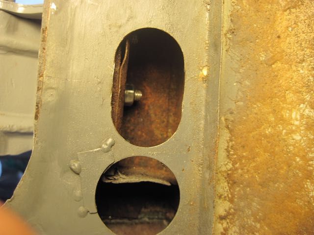
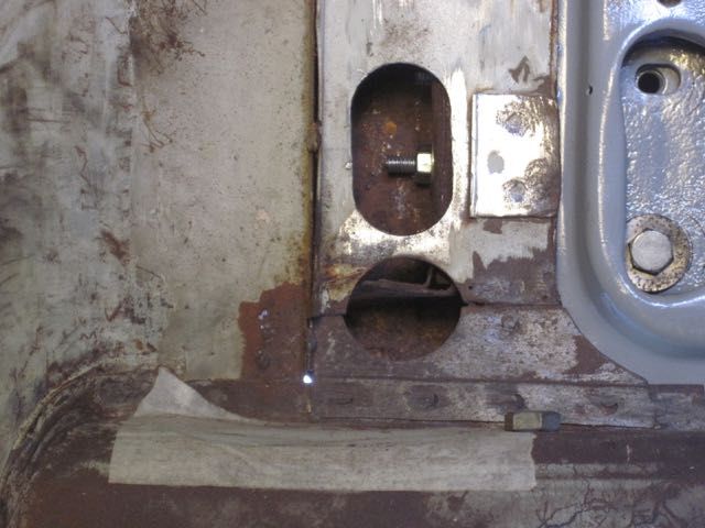
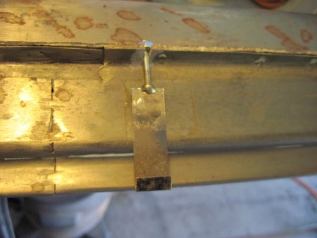
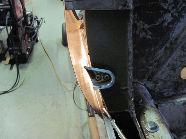
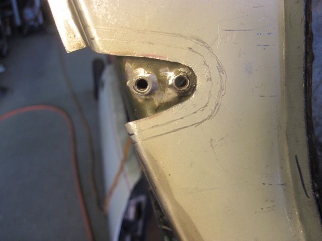
I really had to chew on this one for a while until I came up with a solution. First I spotted this obround hole on the interior side of the A pillar. This one on the driver’s side is just above the weldment that supports the dash and steering column:
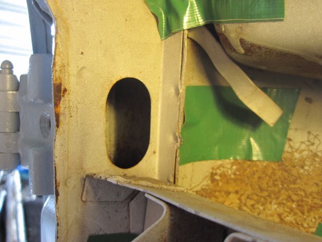
You can see the tips of the screws as the come through the captive nut plate in here, but that doesn’t do any good. Then I realized that I don’t need to get all three of them tight; one will be enough to hold the adjustment. The final piece of the puzzle is to use a nut and bolt, temporarily, in place of one of the screws. Ah-ha. I think I have the answer.
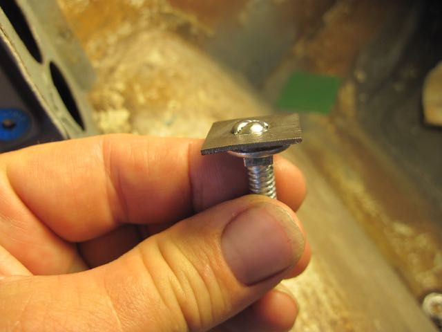
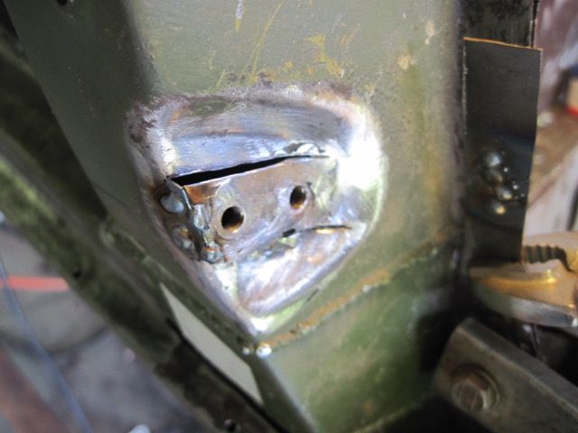
The screws here are M8 x 1.25 mm thread, and I needed a bolt that would pass through the threaded hole in the nut plate without engaging the threads. I used a 1/4 inch x 20 thread carriage head bolt. Just happened to be what I had on hand; M6 x 1 mm would work just as well for you metric guys. I welded a square bit of metal on top to keep it from turning:
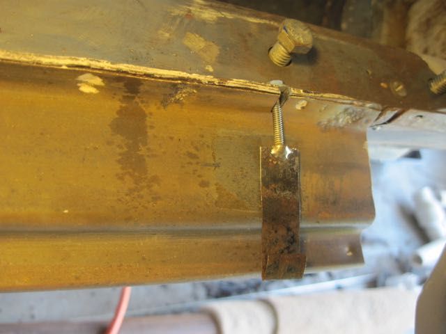
Install the through - bolt in the center hole, and the regular flat head screws in the other two positions. Tighten just snug, then back off about 1/2 turn:
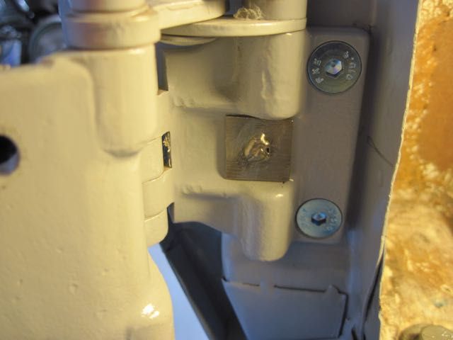
Put a flat washer and nut on the through bolt, inside the A pillar:
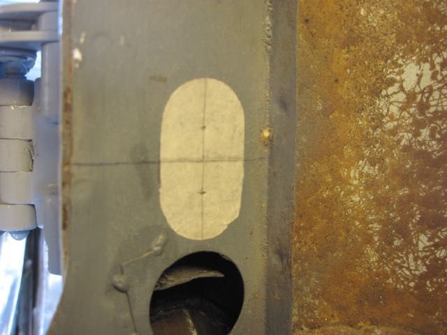
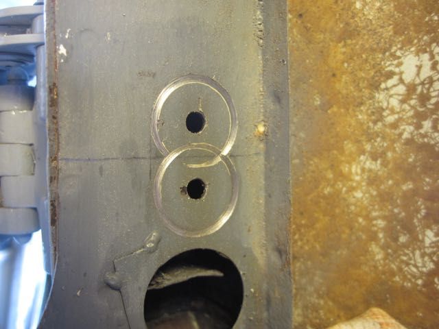
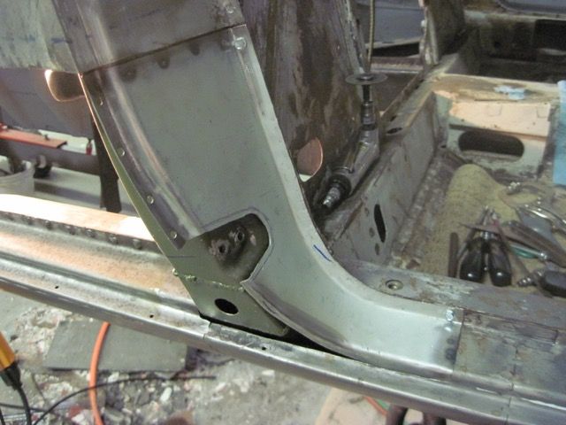
Unfortunately, the factory did not put one of these convenient holes next to the lower hinge, so I had to add it:
Next time I’ll add some more door alignment ideas I came up with.
I’m not done yet, but I have a solution to a difficult problem that I thought I would share with you.
Anyone who has done this already, knows what a pain it is to get the door in just the right position, then get the hinge bolts tightened up without moving the door. It’s not just a pain, it’s impossible. It’s not the bolts that hold the hinge to the door, those are easy. The flat head, countersunk screws that hold the hinge to the A pillar, cannot be tightened with the door in the closed position. They must be loose enough to allow the door to be jockeyed into position, then you open the door enough to tighten the screws, the door slips, and you start over. Again. And again. And again.
I really had to chew on this one for a while until I came up with a solution. First I spotted this obround hole on the interior side of the A pillar. This one on the driver’s side is just above the weldment that supports the dash and steering column:

You can see the tips of the screws as the come through the captive nut plate in here, but that doesn’t do any good. Then I realized that I don’t need to get all three of them tight; one will be enough to hold the adjustment. The final piece of the puzzle is to use a nut and bolt, temporarily, in place of one of the screws. Ah-ha. I think I have the answer.
The screws here are M8 x 1.25 mm thread, and I needed a bolt that would pass through the threaded hole in the nut plate without engaging the threads. I used a 1/4 inch x 20 thread carriage head bolt. Just happened to be what I had on hand; M6 x 1 mm would work just as well for you metric guys. I welded a square bit of metal on top to keep it from turning:

Install the through - bolt in the center hole, and the regular flat head screws in the other two positions. Tighten just snug, then back off about 1/2 turn:

Put a flat washer and nut on the through bolt, inside the A pillar:

Unfortunately, the factory did not put one of these convenient holes next to the lower hinge, so I had to add it:


Next time I’ll add some more door alignment ideas I came up with.
Now that is pretty slick! I like it.
Sheesh - has it really been 3 months since I added anything!? I have been making progress, but got behind with my posting, so now to get caught up.
This door fitting business has really been time consuming. It is one of those jobs that just has to be done, and cannot be over looked in a restoration. A re-paint job or some minor repairs would not be nearly this hard. But I have had to repair or replace parts of the chassis that make up the door frame, and I have “new” (not the originals) doors to fit. The originals are so rusty they cannot be reasonably repaired. The “new” doors do not fit exactly the same, but more on this issue in a bit.
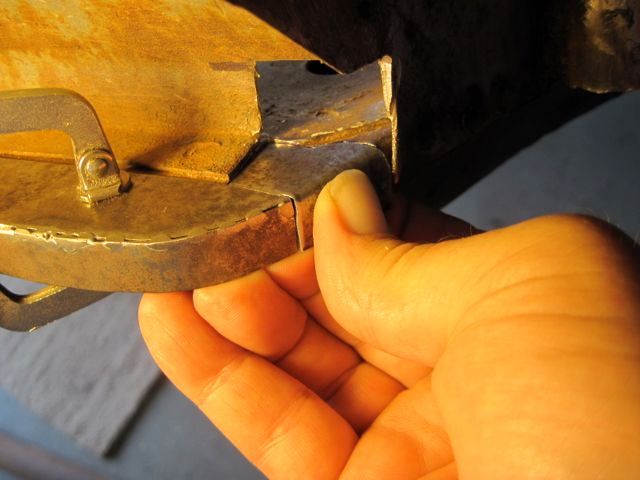
Last time I detailed the way I found to tighten the door hinge screws with the door closed. To do the right side, an access hole to the lower hinge screws is needed, but the fuse holder bracket is in the way.
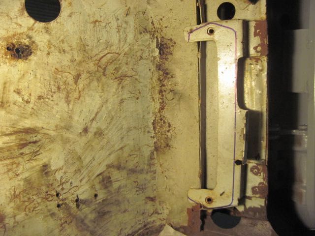
I outlined around the fuse block with a marker, just to be sure I was not about to do something dumb.
The bracket is spot welded on with 2 wide tabs and 2 small ones. I decided to cut them off, and not to try to drill out the welds. It was just easier to do this way. I will weld some new tabs on to the bracket, and put it back in with small sheet metal screws. The metal I left behind will give more thickness to screw in to.
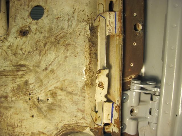
Off it comes, and ready to make the access hole for the lower hinge:
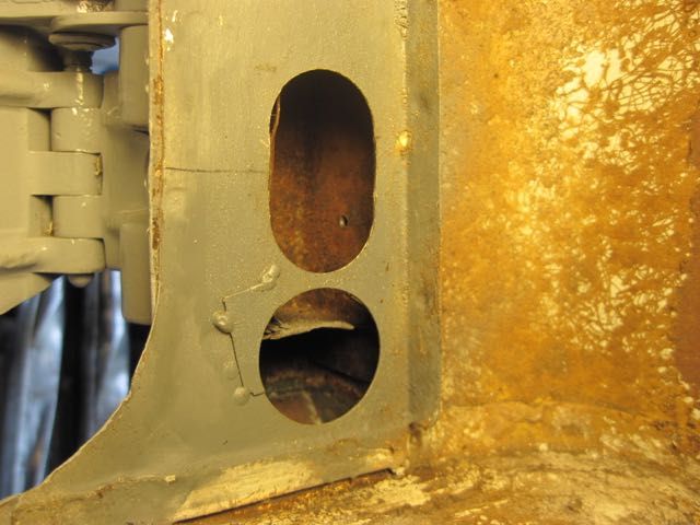
And the result:
To set the height, or vertical position of the door within the frame, I made these little wood shims. They are cut pieces of cabinet shims, and marked with the thickness in millimeters:
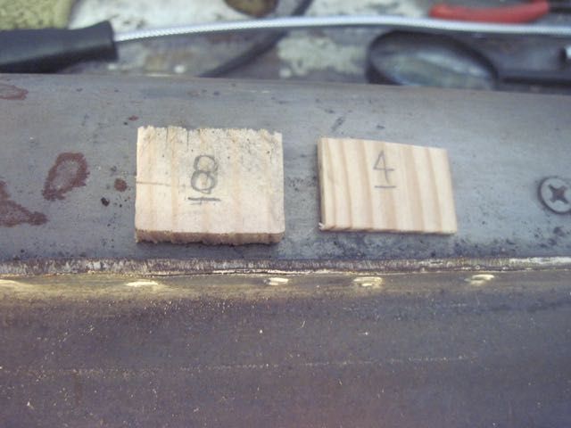
The shims go on the door sill, with double sided sticky tape to hold them (the white patches):
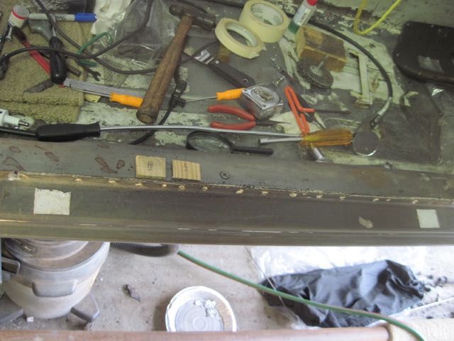
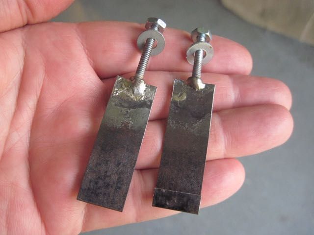
These little tools I made are clips to adjust the door in and out at the bottom:
I had to cut two small grooves in the sill flange, but this will be covered with the door seal later, so I thought no big deal:
The clips grip the door in the drain slots on the underside:
Using the adjustment clips, shims, and modified hinge access feature, it is possible to get a very good door fit with minimum fuss.
This door fitting business has really been time consuming. It is one of those jobs that just has to be done, and cannot be over looked in a restoration. A re-paint job or some minor repairs would not be nearly this hard. But I have had to repair or replace parts of the chassis that make up the door frame, and I have “new” (not the originals) doors to fit. The originals are so rusty they cannot be reasonably repaired. The “new” doors do not fit exactly the same, but more on this issue in a bit.
Last time I detailed the way I found to tighten the door hinge screws with the door closed. To do the right side, an access hole to the lower hinge screws is needed, but the fuse holder bracket is in the way.

I outlined around the fuse block with a marker, just to be sure I was not about to do something dumb.
The bracket is spot welded on with 2 wide tabs and 2 small ones. I decided to cut them off, and not to try to drill out the welds. It was just easier to do this way. I will weld some new tabs on to the bracket, and put it back in with small sheet metal screws. The metal I left behind will give more thickness to screw in to.

Off it comes, and ready to make the access hole for the lower hinge:

And the result:

To set the height, or vertical position of the door within the frame, I made these little wood shims. They are cut pieces of cabinet shims, and marked with the thickness in millimeters:

The shims go on the door sill, with double sided sticky tape to hold them (the white patches):

These little tools I made are clips to adjust the door in and out at the bottom:

I had to cut two small grooves in the sill flange, but this will be covered with the door seal later, so I thought no big deal:


The clips grip the door in the drain slots on the underside:

Using the adjustment clips, shims, and modified hinge access feature, it is possible to get a very good door fit with minimum fuss.
What a lengthy process. Keep up the great work. Cant wait to see it completed
Neither can I.
quote:Originally posted by UFO-LOW:
Neither can I.
Totally understand! You've gone way further down that rabbit hole than I have so far... but the time will eventually come for me to get that deep in. I just want to get mine on the road so I can enjoy for a bit first.
Stunning work though I must say. Truly envious of your skills.
So I kind of got ahead of myself again with the door hinge mod; it was just such a helpful trick for me I thought I should get it out there for others to use. I skipped over the parts that led me to that point. How does that song go … “one thing leads to another”.
Working my way back to front on the right side, I’m going to work next on the rear quarter. The area between the rear wheel arch and the door opening has some bondo there, and the B-pillar and outer rocker panel have rust problems. Hopefully not as bad as on the other side.
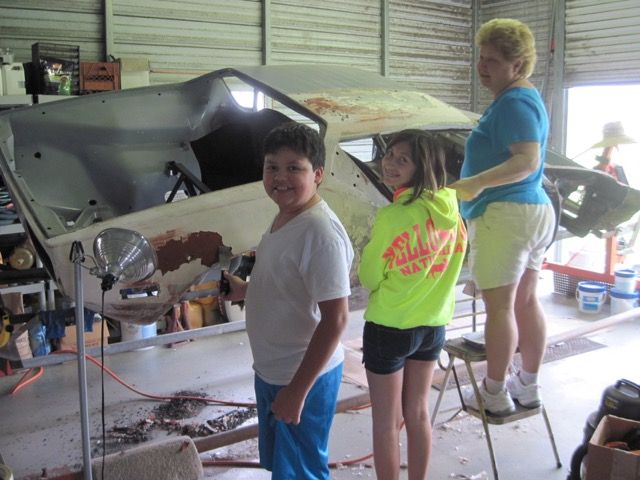
I got some help here - my nephew, daughter, and wife pitched in. They like to destroy stuff:
The bondo is thicker here than I anticipated. Once it is off, I can see why:
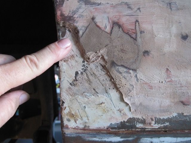
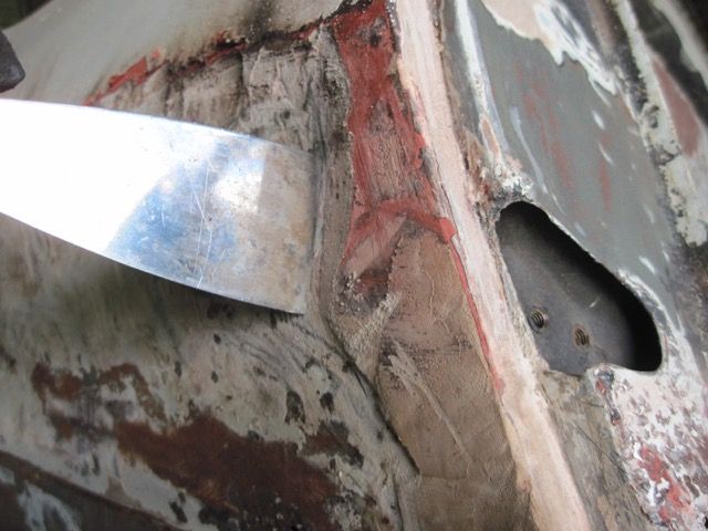
This part of the panel is pretty beat up as you can see. It has some rust through down low where it meets the outer rocker too. Tape guides my cuts to remove it.
Due to the curvature of the panel, I can’t get my spot weld cutter inside, and I could not see all of the welds anyway. Here I’ve used my panel nibbler to cut across the bottom of the panel.
I also have one of Johnny Wood’s B-pillar cosmetic repair panels, so I decided to take these two off together. No need wasting time separating them.
With that out of the way, more rust is exposed:
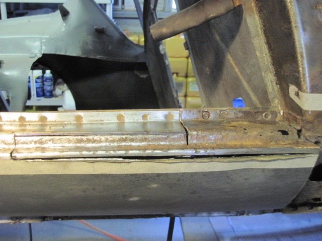
Here I have brushed off the worst of the crud, and can see the flange area. You can see these were not spot welded, but were tacked every 2 to 3 inches:
Now it is easy to remove, and reveals more rust between the flange and the outer rocker:
This section of the outer rocker has to be removed to get at the bottom of the B-pillar:
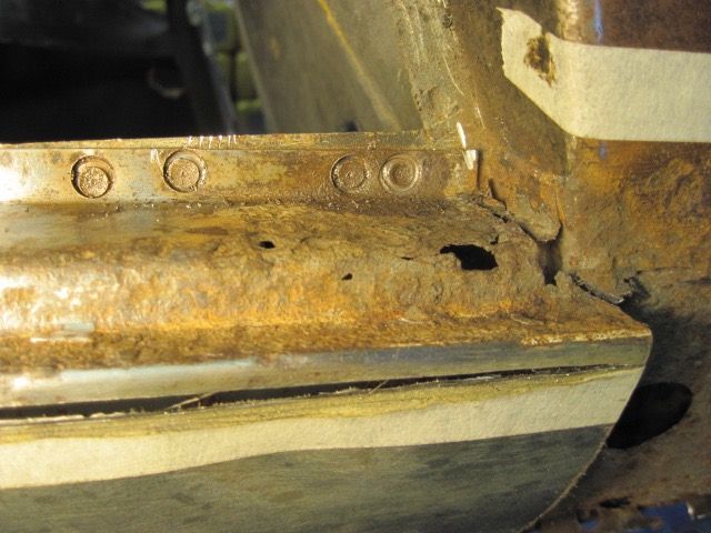
Not quite as bad as the driver’s side, but still bad:
Parts of the outer rocker that were behind the quarter panel here have to be replaced, due to rust:
Now to cut away the rusted bottom portion of the B-pillar:
Behind it, part of the mid rocker is rusted too much to weld on, and has to be cut away also:
Here you can see that rust has even perforated the inner rocker, near the seat belt reel reinforcement. This will be easier to fix from inside the cockpit:
Grinding off the surface rust and spot weld nubs, I am almost done cutting out the bits that can’t be saved.
Next episode, I’ll start shaping new metal and welding it back up. Stay tuned!
Working my way back to front on the right side, I’m going to work next on the rear quarter. The area between the rear wheel arch and the door opening has some bondo there, and the B-pillar and outer rocker panel have rust problems. Hopefully not as bad as on the other side.

I got some help here - my nephew, daughter, and wife pitched in. They like to destroy stuff:

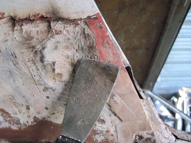
The bondo is thicker here than I anticipated. Once it is off, I can see why:


This part of the panel is pretty beat up as you can see. It has some rust through down low where it meets the outer rocker too. Tape guides my cuts to remove it.

Due to the curvature of the panel, I can’t get my spot weld cutter inside, and I could not see all of the welds anyway. Here I’ve used my panel nibbler to cut across the bottom of the panel.

I also have one of Johnny Wood’s B-pillar cosmetic repair panels, so I decided to take these two off together. No need wasting time separating them.


With that out of the way, more rust is exposed:


Here I have brushed off the worst of the crud, and can see the flange area. You can see these were not spot welded, but were tacked every 2 to 3 inches:

Now it is easy to remove, and reveals more rust between the flange and the outer rocker:

This section of the outer rocker has to be removed to get at the bottom of the B-pillar:


Not quite as bad as the driver’s side, but still bad:

Parts of the outer rocker that were behind the quarter panel here have to be replaced, due to rust:


Now to cut away the rusted bottom portion of the B-pillar:

Behind it, part of the mid rocker is rusted too much to weld on, and has to be cut away also:

Here you can see that rust has even perforated the inner rocker, near the seat belt reel reinforcement. This will be easier to fix from inside the cockpit:

Grinding off the surface rust and spot weld nubs, I am almost done cutting out the bits that can’t be saved.

Next episode, I’ll start shaping new metal and welding it back up. Stay tuned!
Back to work. There are a couple of spots that need patches, more to give me a new surface to weld on than anything else:
Here I have replaced the rusty part of the mid rocker. I have to grind the welds smooth where the replacement piece flanges will be, and more welding will be done. The marker lines help guide me:
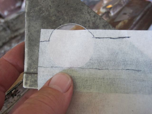
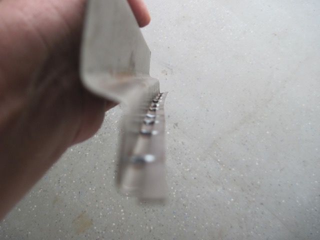
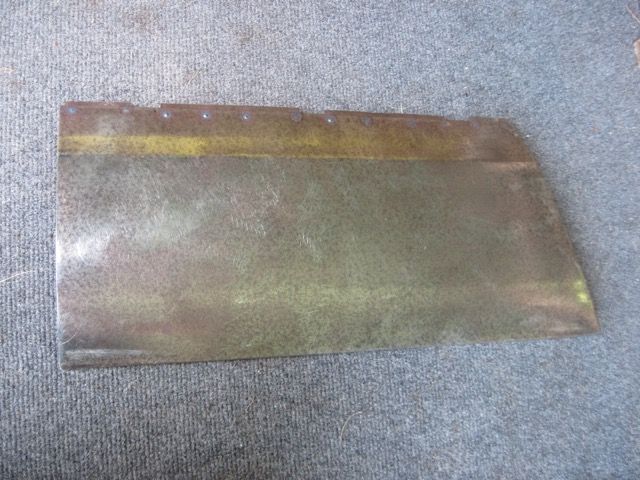
Next I’ll use the heavy aluminum foil to model the repair piece:
This is what it looks like laid out flat. I use this to cut the steel and get the bends right:
Now in steel, being fitted and trimmed:
OOPS. I tried to weld up a rough spot, and blew a hole in it:
This was just too weak to just weld up, so I made a patch:

Clamping and welding the repair piece in place:
Now for the bottom section of the B-pillar repair. Starting with cardboard and tape:
Next model in thick aluminum foil:
This piece is more complex than it first appears:
The steel piece is ready to be welded in place:
Doing the mock ups in light material seems like a lot of extra work, but it actually saves time and frustration.
Next I will do the upper part of the outer rocker here, where it was rust damaged:
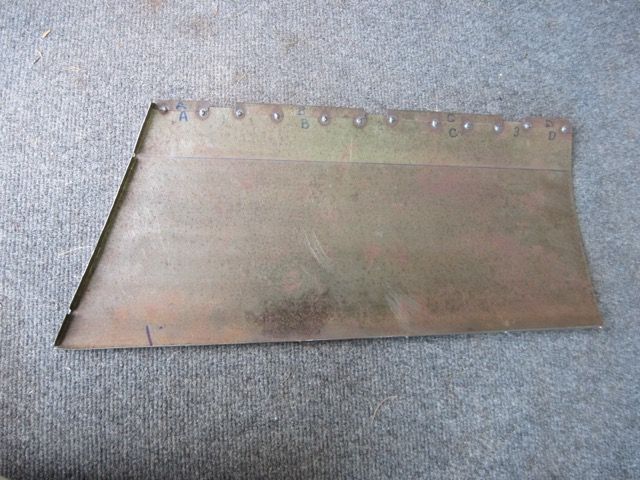
I did not get a photo of this, but I copied the original piece using masking tape, marking the bends with a marker. It is wider at the right than the left, so kind of a tricky piece to make. Took me a couple of tries.
I also decided to cut away more of the original material, even if it was good enough to use. It just made the repair piece more simple. Here fitting and trimming:
Welding on a backer strip:
And finally welding the repair in place:
Next step is to clean up the inside and spray some zinc laden primer in there. I take care to mask off any part where I need to weld later on - zinc and welding do not mix.
Next episode; finishing the outer rocker repairs and starting to fit up the Johnny Woods repair panel. Stay tuned.


Here I have replaced the rusty part of the mid rocker. I have to grind the welds smooth where the replacement piece flanges will be, and more welding will be done. The marker lines help guide me:

Next I’ll use the heavy aluminum foil to model the repair piece:


This is what it looks like laid out flat. I use this to cut the steel and get the bends right:

Now in steel, being fitted and trimmed:


OOPS. I tried to weld up a rough spot, and blew a hole in it:


This was just too weak to just weld up, so I made a patch:

Clamping and welding the repair piece in place:


Now for the bottom section of the B-pillar repair. Starting with cardboard and tape:


Next model in thick aluminum foil:

This piece is more complex than it first appears:

The steel piece is ready to be welded in place:


Doing the mock ups in light material seems like a lot of extra work, but it actually saves time and frustration.
Next I will do the upper part of the outer rocker here, where it was rust damaged:


I did not get a photo of this, but I copied the original piece using masking tape, marking the bends with a marker. It is wider at the right than the left, so kind of a tricky piece to make. Took me a couple of tries.
I also decided to cut away more of the original material, even if it was good enough to use. It just made the repair piece more simple. Here fitting and trimming:


Welding on a backer strip:

And finally welding the repair in place:

Next step is to clean up the inside and spray some zinc laden primer in there. I take care to mask off any part where I need to weld later on - zinc and welding do not mix.


Next episode; finishing the outer rocker repairs and starting to fit up the Johnny Woods repair panel. Stay tuned.
Really impressive work Rodney.
Everytime I open a new episode of this thread, I want to get a welder, and learn how to do what you do.
Great stuff. Thanks for taking the time to post.
Rocky
Everytime I open a new episode of this thread, I want to get a welder, and learn how to do what you do.
Great stuff. Thanks for taking the time to post.
Rocky
Rod, since the shell is stripped and you've done so much rust repair already, have you considered seam-welding ALL the spot-welded inner body panels? Reportedly, it radically stiffens up the whole chassis to the point that paint cracking simply does not happen any more, and may make proprietary frame stiffeners obsolete.
Yes, I am considering it. You did an article or a post on the subject, as I remember. I am just now getting to the point of checking & straightening my chassis. I built a fixed stand, and took the chassis off of the rotisserie today, in fact. I'm also going to do a 6 point cage.
For what it's worth, if you haven't closed up the rockers yet, you may want to open up the B post bottoms you repaired. Part of the internal rust problem in the post is the dust that collects in the bottom from the openings in the structure running from the back of the car. Once it's finds it's way to the post, it lays there holding moister rotting out the post bottom. This happened quickly when the post is raw but the dust will still lay there.
This was a very clean car and I still got a bag full of dust and crap from the holes drilled into the post bottoms.
This was a very clean car and I still got a bag full of dust and crap from the holes drilled into the post bottoms.
Attachments
Images (1)


Yuuuukkkkkk! Yes, I did add some holes and gaps so that moisture and trash would not get trapped. My photos just don't show them well. You are right though. I found the worst rust where dust, sand, and leaves get trapped and hold moisture.
This is just a patch piece where rust and drilling out spot welds left me little to work with:
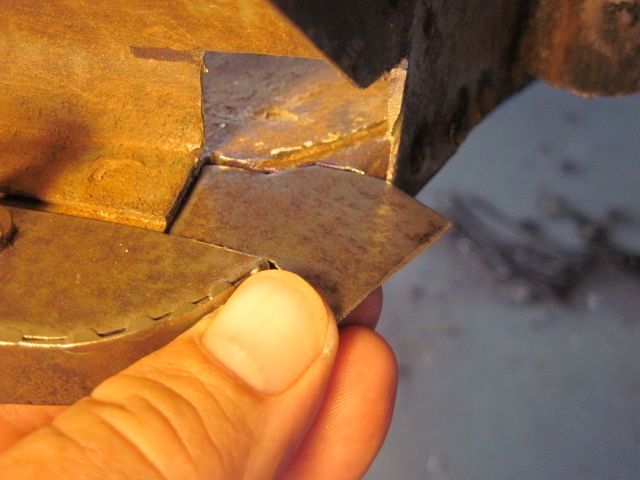
Here I have decided to save as much of the original outer rocker section as I can. It looks simple to make, but it is not. The bend radii, distances, and curvature have to be just right or it will not fit.
Only the bottom part was rusted out; repairing this segment is much easier than re-making the whole panel section:
Now I am starting to rough in this larger repair panel:
Here I am making the flange on this repair panel where it mates up with JW’s piece:
Starting to take some measurements. This sits out too far:
This curve needs to be sharper, to make this panel sit back farther:
Not so easy to do. I hate to cut into Johnny’s fine panel, but I have no choice:
With that lower corner segment removed, I can use the shrinker & stretcher on the flanges that remain, and massage this piece to fit my car:
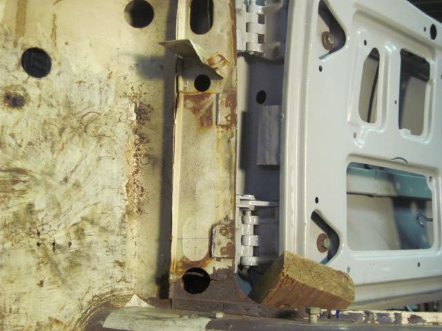
I used the old door to check the alignment of the guide:
Sketching the cut out for the guide:
Getting there:
The mounts for the guide had to be pulled forward and angled up a bit. This was a pain in the butt to do. This pic only shows it partly done, I finished it up better than this.
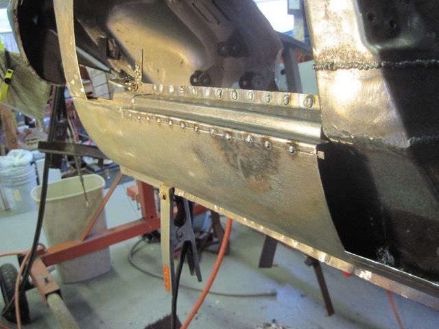
Now I’m finally fitting up both panels:
I’m welding on some backer strips. The gaps are there to allow for some panel clamps to hold the panel on flush while I weld it back on the car:
The set back of JW’s panel flange was just a bit too deep, so I cut the whole thing off and made a new one:
Here is the slightly modified panel ready to install. I added a small tab inside, above the guide cut out, to push the panel out slightly and make it fit up to the guide better. Below the guide cut out, I added another to prevent the screws from being dropped down inside the rocker panel:
Finally ready to weld it in place:
Followed by the big one:
Again, I am missing a picture of this area finished metal working. I’ll add it later.

Here I have decided to save as much of the original outer rocker section as I can. It looks simple to make, but it is not. The bend radii, distances, and curvature have to be just right or it will not fit.

Only the bottom part was rusted out; repairing this segment is much easier than re-making the whole panel section:


Now I am starting to rough in this larger repair panel:


Here I am making the flange on this repair panel where it mates up with JW’s piece:

Starting to take some measurements. This sits out too far:

This curve needs to be sharper, to make this panel sit back farther:

Not so easy to do. I hate to cut into Johnny’s fine panel, but I have no choice:

With that lower corner segment removed, I can use the shrinker & stretcher on the flanges that remain, and massage this piece to fit my car:


I used the old door to check the alignment of the guide:

Sketching the cut out for the guide:

Getting there:


The mounts for the guide had to be pulled forward and angled up a bit. This was a pain in the butt to do. This pic only shows it partly done, I finished it up better than this.

Now I’m finally fitting up both panels:

I’m welding on some backer strips. The gaps are there to allow for some panel clamps to hold the panel on flush while I weld it back on the car:


The set back of JW’s panel flange was just a bit too deep, so I cut the whole thing off and made a new one:


Here is the slightly modified panel ready to install. I added a small tab inside, above the guide cut out, to push the panel out slightly and make it fit up to the guide better. Below the guide cut out, I added another to prevent the screws from being dropped down inside the rocker panel:


Finally ready to weld it in place:

Followed by the big one:


Again, I am missing a picture of this area finished metal working. I’ll add it later.
Nice work and excellent documentation. I am wrapping up presently a similar project.
As always UFO.. I love your jump in and do it attitude. Well done sir.
Love being able to see the details up close. Great work!
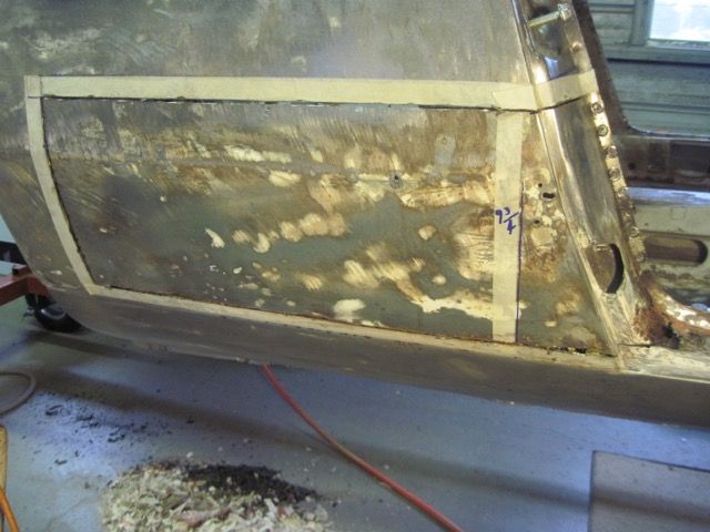
Here is the area as it looks now:
You can see I have some cosmetic touch up to do, but it came out OK.
I know I took more pics of this - Apple "upgraded" from "iPhoto" to "Photos", and ever since I can't find a bunch of pics I've taken. Grrrr.

You can see I have some cosmetic touch up to do, but it came out OK.
I know I took more pics of this - Apple "upgraded" from "iPhoto" to "Photos", and ever since I can't find a bunch of pics I've taken. Grrrr.
Fantastic work Rodney. I am surprised you had to modify the outer B post I sent you. I thought I had got the shape correct on my former? I have sold lots of those panels and have never heard anyone say the lower corner is the wrong shape. I have a friend who has just bought a rust free car that has never been welded - I will take some profile measurements from his car and check them against my former and make adjustments if it's wrong.
Regards, Johnny
Regards, Johnny
Hi, Johnny! I had no idea you would be following my thread. First, thank you; your compliment is high praise coming from you - I've seen your work. Certainly I appreciate all the comments; there are a number of people here that are doing really top notch work.
Part of your confusion may be - I did not buy this piece from you. I bought it from another owner here state side, who bought it from you and did not need it. I only have the right one, not the left. I also have your front valance replacement, but have not used it yet.
I will PM you soon with photos and details of the changes I made. I am pleased with your product, and not at all upset that it needed a few tweaks to fit. If I can help you improve it, all the better.
Regards, Rodney
At last now, I’ll get to the issues that motivated me to do the door hinge adjustment mods. Some of my commenters suggested that I do some fitting of the doors before I get too far along. Since I’ve done some significant work around the door frames, and also had to buy a different set of doors to replace my rusty ones, that seems like a good idea. Little did I know what lay in store for me.
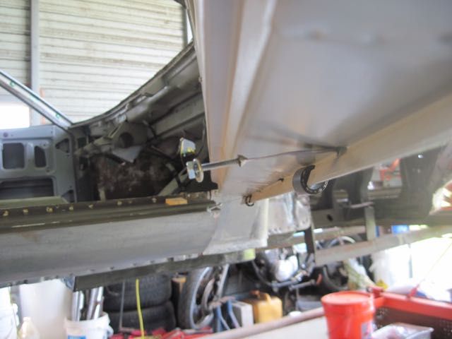
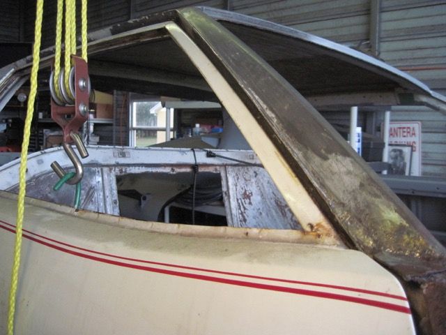
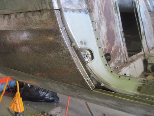
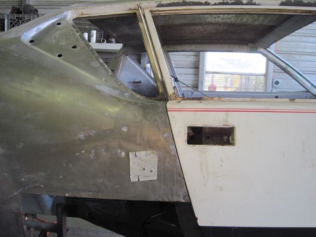
Many Panteras, I dare say most, have doors that do not fit properly. Among the more common issues is striking, or rubbing, of the extreme top rear of the window frame on the trim piece. Mine had evidence of this problem also:
I attempted to fit up one of the old doors, to take some measurements and see if this problem could be due to poor adjustment. At this point, I realized that I could not get a repeatable adjustment, and so made the door hinge adjustment modifications I detailed earlier.
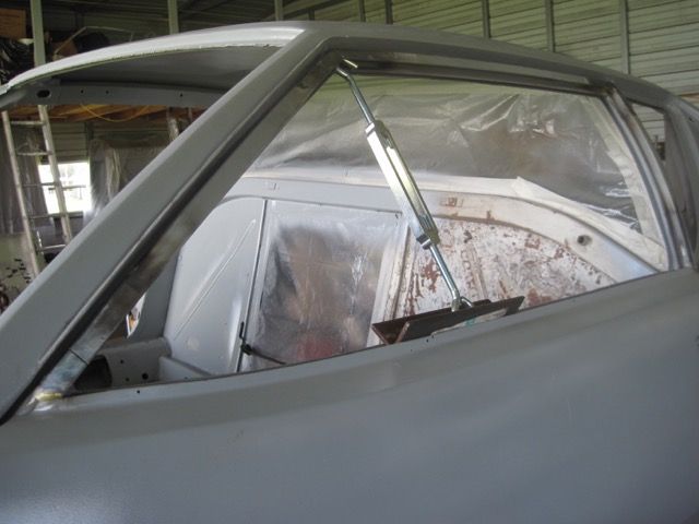
Here I have put the old door in place, and found that I could (just barely) avoid the rubbing problem with careful adjustment. Notice in this pic the door to body gap, also the window frame gap is uniform:
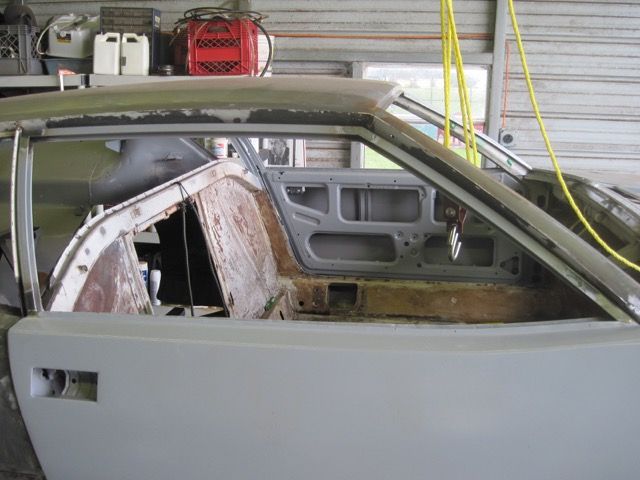
Here is a new door in place, again after careful adjustment. Not easy to see in this picture, but the door to body gap is uniform, but the window frame gap is not. It is wide at the bottom, and tight at the top. The rubbing cannot be adjusted out:

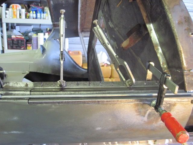
After a couple of weeks of screwing with this, trying every trick I could think of, I finally decided the only way to fix the issue was to warp the window frame ever so slightly. To do this, I had to cut the window channels in each corner, only enough to weaken them:
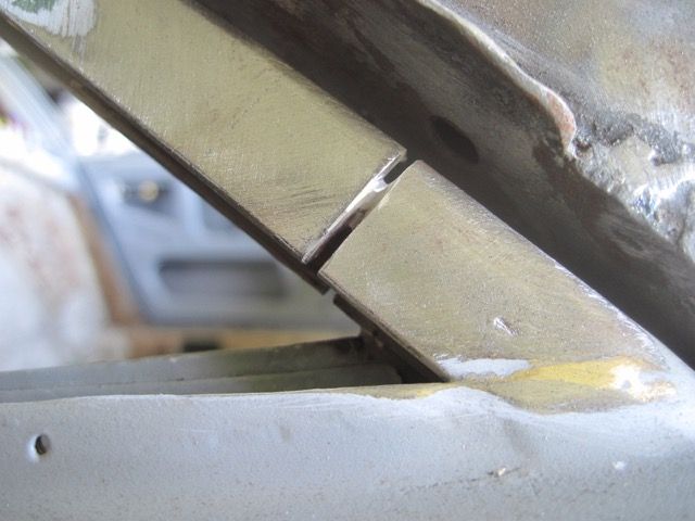
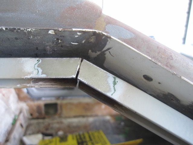
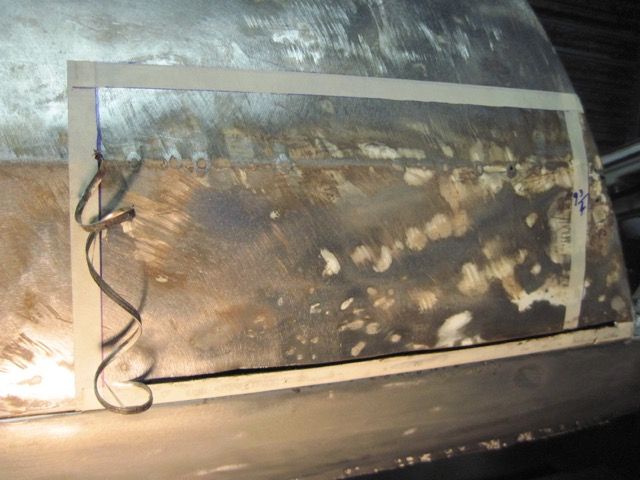
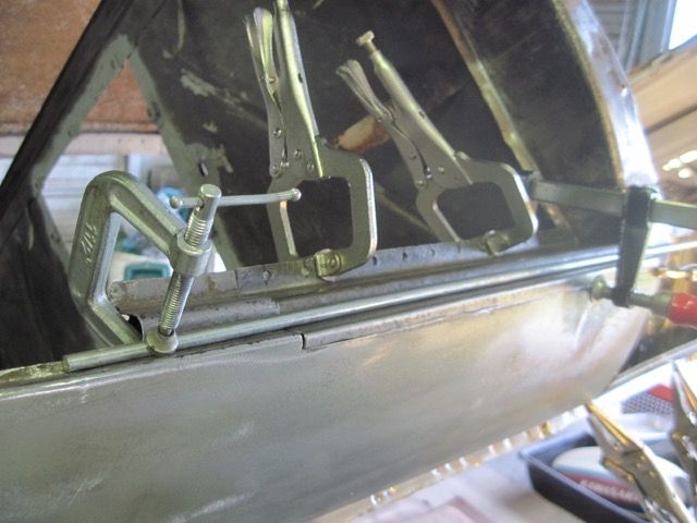
With a Dremel tool and the finest cutting disks, I sliced into each corner. You can imagine this caused some real heartburn. If I messed up, I could ruin the doors I just bought. Then I rigged up a turnbuckle to put pressure inside the frame, and warp it until the rubbing problem was solved:

Finally, I welded up the cuts to restore the strength and hold the shape.
In case you were wondering, the left (drivers) door had the same problem, and had to be done also.
So now you know the rest of the story.
Many Panteras, I dare say most, have doors that do not fit properly. Among the more common issues is striking, or rubbing, of the extreme top rear of the window frame on the trim piece. Mine had evidence of this problem also:

I attempted to fit up one of the old doors, to take some measurements and see if this problem could be due to poor adjustment. At this point, I realized that I could not get a repeatable adjustment, and so made the door hinge adjustment modifications I detailed earlier.
Here I have put the old door in place, and found that I could (just barely) avoid the rubbing problem with careful adjustment. Notice in this pic the door to body gap, also the window frame gap is uniform:

Here is a new door in place, again after careful adjustment. Not easy to see in this picture, but the door to body gap is uniform, but the window frame gap is not. It is wide at the bottom, and tight at the top. The rubbing cannot be adjusted out:

After a couple of weeks of screwing with this, trying every trick I could think of, I finally decided the only way to fix the issue was to warp the window frame ever so slightly. To do this, I had to cut the window channels in each corner, only enough to weaken them:


With a Dremel tool and the finest cutting disks, I sliced into each corner. You can imagine this caused some real heartburn. If I messed up, I could ruin the doors I just bought. Then I rigged up a turnbuckle to put pressure inside the frame, and warp it until the rubbing problem was solved:

Finally, I welded up the cuts to restore the strength and hold the shape.

In case you were wondering, the left (drivers) door had the same problem, and had to be done also.

So now you know the rest of the story.
It worked! My photos are out of hock! 
did you pay the ransom OR send in the A-Team?
I used the ~original hack.
After the .jpg before the [/img] put ~original ,or otherwise stated: .jpg~original[/img]
After the .jpg before the [/img] put ~original ,or otherwise stated: .jpg~original[/img]
Add Reply
Sign In To Reply