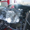
Nate, I'd never thought about even the risk...! In my one time up on this, I think I used the intake manifold in the first step only to support the engine lifting plate---and the only thing I'm sure of is that I installed sealant (and torqued, if not even re-torqued) with the engine in place in the engine bay. And then re-stabbed the distributor, and then the replacement oil pan...Lee
@nate posted:Back to the jackshaft assembly for a moment...I've always tried to install the jackshaft and intake manifold at the same time, torqueing all bolts in the proper sequence, and avoided removing the jackshaft alone later for fear of promoting manifold leaks.
Thinking now this is excessive caution.....but it begs a question: If the jackshaft is removed by removing it's four main bolts/screws, should the 8 other manifold bolts be loosened and ultimately re-tightened in proper sequence, or should they just be left alone, to minimize possible disturbance to manifold sealing surfaces?
I can see an argument for either option, anybody end up with a leak after R&R of a jackshaft? Thanks! Nate
I'm VERY likely wrong on this, but since there is relatively little force exerted on the intake manifold compared to main bearings, cylinder heads, and such, I wasn't particularly worried about disturbing the seals. Of course the fact that I hadn't even considered that MIGHT have been a contributing factor.
Hopefully this rebuild will be the last one for a while and will be torqued to spec with the jackshaft in place.
MH
Into the rabbit hole we go!
After MUCH deliberation I have decided to go back almost completely stock with the engine, I will send the engine off for a complete refresh/rebuild. I'm considering some minor improvements to valves and cam, but haven't made those decisions yet. I also have a set of "never installed" Hall Pantera big bore headers that I'm considering... If I can mount the heat shields to hide them, I may go that route. The main goal is to keep as close to original (at least externally) as possible.
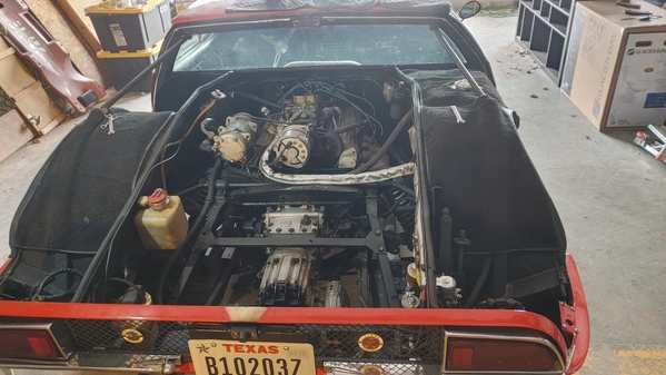
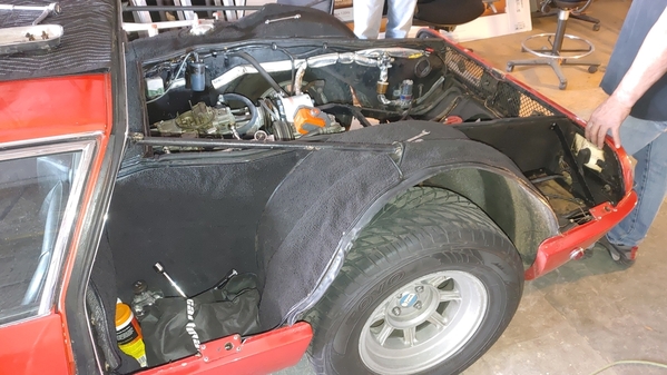
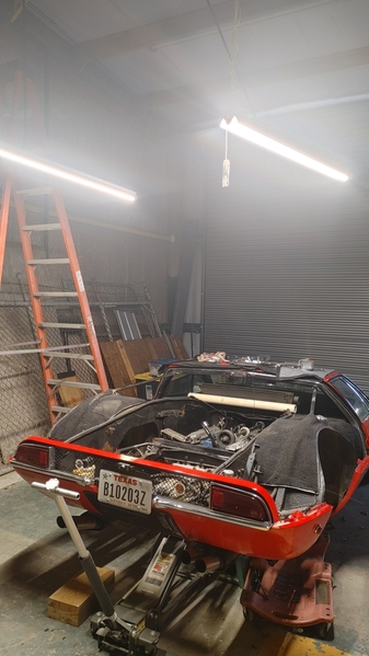
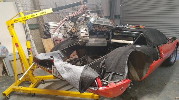
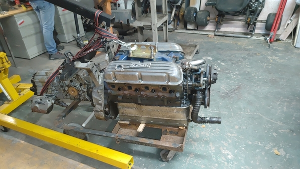
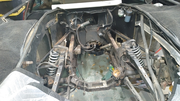
I drilled discreet alignment holes on the spine mounts AND the wing mounts on the left side, removed the left wing, then the spine with the right wing still attached. A far simpler task than I had feared!!! a minimum 2 man job ( I had three just in case), but not difficult at all. In a car known for pushing the envelope of the term "difficult", this was a pleasant surprise...
These pictures were early in the day. I've since removed the spare tire support beam, alternator, A/C compressor, carb, distributor, plugs and detached the exhaust manifolds.
Next session will see the seats and console come out to access the portal and remove the jackshaft and coolant hoses.
I'm still undecided on whether to remove the ZF first or to pull the engine and ZF together.
What is the proper procedure for removing the frame bridge and the other Assembly/Bars/Doohicky that the upper shock mounts are on (I'll just call it the "ABD" for now}? I think that I need to put the car on jackstands and take the weight off the shocks but I'm waist deep in new waters here. Do I need to put another jack under the ZF?
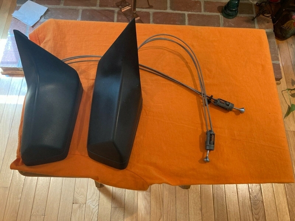
On a side note, I scored a set of Dodge Rampage mirrors for $95
That gets everyone up to speed. suggestions, warnings, advice and even criticism are all welcome at this point.
MH
Attachments
M!ke, I installed with ZF attached, using a balance tied to the ZF in the back and a carb plate--angled with the ZF up to nose under the 'shelf' on the rear bulkhead. I don't remember it clearly (so good news, must have been uneventful ![]() ) but I think removal is (after the engine mounts are unbolted) to loosen the alternator bridge (relieve pressure on the springs, pull the shock bolt and move the bridge out of the way, then re-stab the shock with the bridge in place. Support the ZF and remove the ZF support, then chain the engine balance to the ZF and carb plate. I think no secret at all, really, you've already done the hard work! Lee
) but I think removal is (after the engine mounts are unbolted) to loosen the alternator bridge (relieve pressure on the springs, pull the shock bolt and move the bridge out of the way, then re-stab the shock with the bridge in place. Support the ZF and remove the ZF support, then chain the engine balance to the ZF and carb plate. I think no secret at all, really, you've already done the hard work! Lee
Attachments
Looks like the jackshaft should come off before the pull, is that correct?
she's almost ready to come out... just a few hoses to go...
MH
Yes, my suggestion is remove the whole jackshaft assy off the manifold, or at least the front pulley (since the pulley nestles under the rear bulkhead metal...or at least, is one less thing to pop thru the window)--Lee
@lf-tp2511 posted:“I will have the ZF vapor blasted….”
I assume you mean blasting with dry ice pellets?
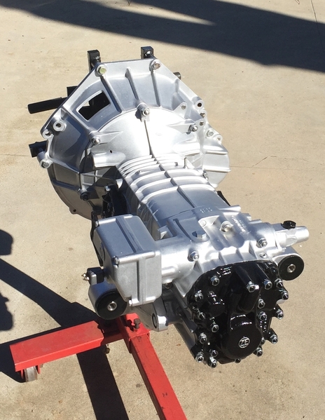
I was able to find a local business that did that for my ZF during the reassembly of 2511. It gave a very clean surface but it didn’t return everything to the same uniform appearance. It seems cast aluminum pieces, after 50 years of use, are hard to return to original.
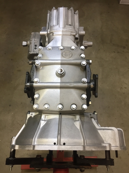
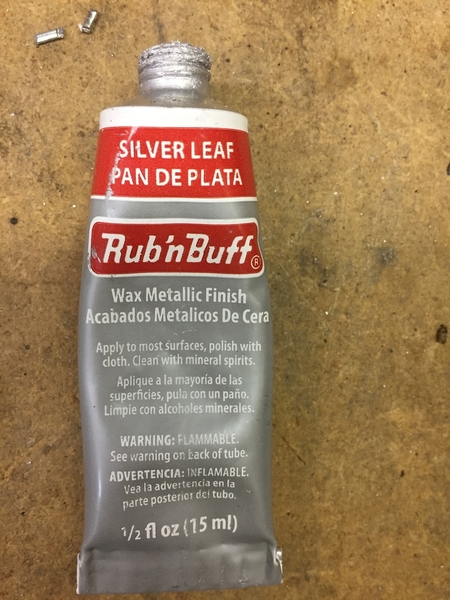
I chose to do something others have used before me, a colored Carnuba wax called rub n buff. As others advised me, it seems to be holding up quite well and allows the bell housing and the ZF case to have matching appearance
left side is with the wax, right side is the dry ice blasted finish. there is a darker gray wax available that would be a closer match to the cleaned surface, but I opted for a little bit more shine
it comes in a 1/2 ounce tube and the coverage is phenomenal. I used one tube and maybe 1/4 of a second tube for the entire projectLarry
Looks great.
Vapor blasting is a combination of water and glass beads. It leaves a low gloss gleam kind of like a new Edelbrock intake manifold has.
It's kind of new to the "US" as "restorers" and is more of an industrial finish. So if you find someone locally that does it, likely they are industrial and caution should prevail on the consideration of the handling of your ZF. Like they would give two shits if they wrecked it for you?
I only know of one guy "in the hobby" doing it. It's part time for him and he does it in the back of his garage. Not here. In Texas and you need to get the parts to him and I'm not sure how good he is at shipping the stuff back to you?
It definitely will give you the "new gleam" that you want on the case.
I think a regular old Pantera has a much cooler look and styling ( not very Supercarish ) than a Goose and I never really closely looked at one but, I will say the jack shaft that operates the A/C compressor is awesome, what a neat design.
What has been called vapor blasting is more commonly referred to here in the US as dustless blasting. It can use different medias but they are always mixed with water, thus the name dustless blasting. I don’t know what the gentleman in Texas might be doing that is unique, but vapor/dustless blasting is offered just about everywhere these days.
I think the term “vapor” is a misnomer. it does not miraculously vaporize but instead leaves a muddy sludge which I suppose has some advantages over a dust storm. 🤷♂️
I would never consider any media blasting on an assembled ZF. Strictly an approach to do on an empty case.
The beauty of Dry Ice Blasting is there is no media to get blown inside and grind up the gears. The “media” is the dry ice and yes it does turn to a vapor, with the only residue being left behind is the material that was removed from the surface. For this reason it is often used in food processing facilities on processing lines
do a YouTube search for Dry Ice Blasting and you will find there are specialists in the automotive hobby world working wonders with this approach
Larry
Have you ever seen a Magnusen supercharger on a C6 w/LT2 or an SSR. The blower is driven from the rear with a jack shaft. 
Jack shafts, what a concept. Larry, a friend of mine has two truck mounted blaster as you describe. He keeps these going by doing prep jobs at Legoland, Sea world, Disneyland and government places that require minimal impact to the environment. I have used this system to do complete cars but, all the materials get expensive even though I get to use the machine for free. It is still a lot of work so, I just hall everything to my blaster guy and be done with it.
Donny,
are we talking about the same thing, Dry Ice Blasting? The only materials needed are the Dry Ice and the machine.
I have never priced blocks of dry ice, or tanks of CO2 if the machine is high end and makes its own pellets, but I don’t think it is terribly expensive?
Larry
M!ke, a neighbor of mine in New Ulm had 5 BMW motorcycles, none newer than 1964 and each beautiful. His answer to restoring aluminum--WD40. That simple, same logic as lanolin for leather---it floods out the dirt and provides a consistent finish, voila. Not that I'm sorry that I once polished out the valve covers on the 308 (like I'm not sorry for polishing the water tank in the Goose!), but though its sad, its true, the cool thing in the Mangusta engine bay is not the drive train--you can barely find it under everything--its really just the open tube frame...
Denis, that is one mean application for jackshaft (!) An an interesting exercise in packaging for DeT to have enabled the engine to be just a few inches towards center. One of my favorite Binky episodes is the most recent one--even after 36 episodes of making brackets... The issue they had with their flex shaft (where the inertia of the accessories was tearing it apart and so they built the clutch function on it) was pretty amazing. Thanks for the tip on that channel so long ago--Lee
When your doing large projects like a car getting it inside and out it can can cost a lot and take much time but, if your doing separate smaller parts, no biggie. Several years ago I bought a Barrel blaster for doing smaller to medium size parts that works awesome, It's made in the great state of Texas.
Is it safe to assume the shifter linkage yoke will slide out of the ZF when I lift the engine or should I remove it (and if so, how)?. From the looks of it, the oil filter must be removed too... Does that mean the engine has to be reinstalled sans-filter? Last oil filter change took me 20 min to get the filter out. PO swapped oil pan For a custom pan which didn't make it any easier.
I should have the engine out this weekend
While the engine is at the machine shop I'll begin the engine bay restoration... as well as suspension...
MH
Attachments
What ever you do do not unscrew the yoke. Pull the pin forward of the joint. That way there will be no need to re-adjust the shifter when you re-assemble the car.
Mike, you will need to separate the ZF; I just remember this was damn hard, everything was stuck....But the shifter fork is secured inside the shifter box by 2 "grub" screws--using maybe ~4-5mm allen wrench screws that access thru the small rubber grommets on the top of the shifter box. The pin that held the rear of the yoke is still stuck for my car, I think others have noted that the hardened pin just gets harder if you try drilling on it...Since the adjustment on the front was also stuck (had to take it to a machinist who put huge amounts of heat on it, its bathed really well in anti-sieze now and I think I located a new giant fine-pitch nut.). But I may have taken the U-joint apart to get the engine out of the car.
I actually thought adjusting the shifter was not difficult on re-assembly. If you can't punch out the pin, and are going to try and drill, get some amazing drill bit and make sure its cutting...Lee
Attachments
Glad I asked !!! I was hoping it was similar to the yoke on a driveshaft that just slides into a transmission... Denisc, i'll have a look later today to see if I can find the pin you referred to.
Thanks guys...
MH
Mike, here is another view; the pin that Denis mentions is definitely the best to access, its worth spending a long suffering time to try and pull it out. Otherwise, the access to the 2 grubs screws is shown here, once removed then yes the shaft can slide forward out of the arm that responds to left/right gear selection...
There should be a boot right outside the shifter box on the shaft, mine evaporated but you must have either grub screws or the "pin" removed to replace. I think I simply unscrewed at the adjustment coupling on the far side of the U-joint to detach from the shift linkage. I've since found replacement u-joints (3 of them somewhere on the shelf, feel free to look, just leave me one for the day I get a chance ![]() .
.
The then 40-something year old seal finally started seeping after all put together...the shift box should be dry, but suggest getting a replacement seal (it and the grub screws are cheap at Wilkinson, same as the shift boot).
Attachments
Alas, I didn't see that pin... I ended up marking the set-nuts on the turnbuckle adjuster bolt and then unthreading it...
Then I log in to read Denis's "Whatever you do" warning NOT to do what I had JUST done... (a recurring theme in my life).
So, last night a friend from the Ferrari world (who is helping me on this project) and I went to go see that 'other' goose in town.
Lee, you might recognize this one
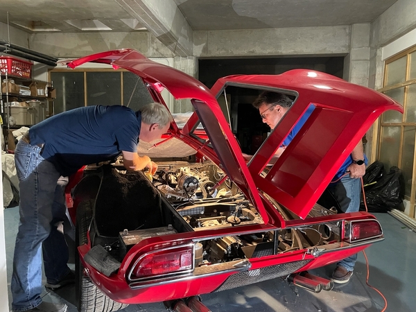
I wanted to get a look at a proper engine bay... While 898 seems to be very original, Various parts have been replaced over the past 53 years and not always with the correct parts.
@johnnywoods I've been pouring over the gorgeous engine bay restoration you were kind enough to document online. I wanted to ask about the zinc/passivate plating that you had done, was that personal choice, customer request or "factory correct"? I love the look, but haven't seen much of that in other Mangusta pics... Of course rattle can black spray paint IS a cheaper solution many others (including msyelf) have turned to from time to time.
MH
Attachments
...good to see my own car for the first time in just over 2 years since Covid ![]() At first glance, it could have been your's or Denis' car ! In my car, the only 3 things that are yellow are the polished brass water tank and the Lucas 4ST solenoid on the right...4ST was the right solenoid by the time 1076 was actually built, but I've got a silver zinc 2ST waiting on the shelves there (that just looks to weird not to use!). Lastly, the air valve on the smog pump is yellow zinc/cad---yes, I at least want it back in place on the right of the car, even if a working system (esp, air injectors won't work with the Hall headers on the car now) is a long way from installation.
At first glance, it could have been your's or Denis' car ! In my car, the only 3 things that are yellow are the polished brass water tank and the Lucas 4ST solenoid on the right...4ST was the right solenoid by the time 1076 was actually built, but I've got a silver zinc 2ST waiting on the shelves there (that just looks to weird not to use!). Lastly, the air valve on the smog pump is yellow zinc/cad---yes, I at least want it back in place on the right of the car, even if a working system (esp, air injectors won't work with the Hall headers on the car now) is a long way from installation.
I love the look of yellow zinc, but it may be a 70's and later thing and (Dick has emphasized this) (except for some with yellow rear springs) there is really no yellow on the car. Even, a lot of fasteners I replaced with nice shiny clear zinc, um, are 'correct' in black. For example, a lot of the M10 nylock nuts in the engine bay are clear zinc with yellow or red inserts...brand new shiny yellow-insert nylocks are available (not cheap, but only a few needed) but the big screws are supposed to be black. This makes the engine bay pretty much a black hole, esp when the carpeted trays are in place. Pretty much, in the rear is the spare tire, forward is the air-cleaner, and on the sides are the air tubes with the aluminum trays above all that. I can understand why a little yellow glimmer is not 'correct' but pretty darn eye-catching...
For the vinyl edging that goes around the lower engine bay--of course the original stuff is fake chrome, but the golden look after aging (see the pics of 8ma1074) against the red is so cool that I've ordered yellow-gold edging instead...maybe it will be too brash, I hope so ![]() .
.
The detail I haven't even attempted is the undercoating texture in the engine bay--everything is smooth epoxy. Original was a wonderful splatter everywhere--and I wish I knew how to get those textures.
Detail painting in the engine bay isn't done, I will someday detail as I saw 8ma1074 (half-black on the engine latches, across the rear bulkhead, and of course the engine covers).
Some day...meanwhile, just great to have free storage at the brother's house and have time to think about the trivial details (since I can't be there to actually get the car in one piece and drive ![]() )--Lee
)--Lee
Another dive into the abyss
It really wasn't that bad of a pull, now to start on the suspension and engine bay restoration!!! Which of course begins with cleaning the huge pile of parts.
@leea did you keep the internals of your engine stock? I know you were a proponent of the 331 Stroker, but I never asked which route you took.
I will get the engine shop started on checking out the engine and giving it a refresh/rebuild next week... while they do their thing I'll be making a list of needs, wants and questions!
As always, suggestions/advice/warnings/etc. are ALL welcome
MH
Attachments
Mike, the decisions on the rebuild were made so long ago, but the only mods I made were to have the conn rods polished and shot peened (you know, why not) but then for spec only went with a more aggressive hydraulic camshaft. That requires modifying the heads for an adjustable rocker setup, so screw-in studs and guide plates. Pretty ordinary work for an engine shop. Since the original cam was the same thing probably used in station wagons (and since the heads are closed chamber and have healthy compression ratio, friendly to more cam already).
A stroker kit and a roller cam would be a super nice setup--but in the big picture, completely unnecessary and (expecting that the core of your engine is healthy), just the minimum bore with new rings and balancing will keep you happy.
In the meanwhile, great time to scrub up and DP90 the frame...If you want to re-install the water valves, you might trace the brackets on my car and the valves are easy to find. Boots for the heim joints, finding some modern replacement for the asbestos heat shields up front, new rubber hoses everywhere--are a nice gift for a 53 year old car...Lee
If money is tight, ultimate horsepower is not a goal, the block is not too worn and it already has certain types of forged pistons, they can run with as much as 0.005" of clearance, since they expand greatly with heat. In such cases, you can get away with a good honing and re-use well cleaned used pistons with new rings.This is a "freshening", not a complete overhaul and is commonly done in all kinds of racing engines. Honing is far cheaper since less set-up is needed and you wind up with stronger (thicker) cylinder walls.
But if you have cast (stock or hypereutectic) pistons in a used block, an economy freshening will not work and you're stuck with overboring and new pistons. Good luck.
...and if you are really lucky, the crank is worn and needs replacement with a longer stroke ![]() . But if unlucky, just a really nice running motor is not a bad thing in an old car...Lee
. But if unlucky, just a really nice running motor is not a bad thing in an old car...Lee
We'll find out soon enough if the crank is worn... I'm having the block, crank and heads checked out. Turns out the cam was a "Moon" aftermarket model, so I'll be looking at options there as well.
Anyone have sources for the rubberized padding/soundproofing along the firewall?
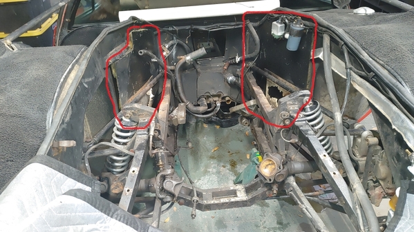
Are these sheet metal panels to the left and right of the engine factory or added? They are thin sheet metal with some sort of fiberglass insulation behind them. They are mounted to (4) 1" standoffs each from the outer walls
Also, should the frame (for lack of a better term) be glossy or semi-gloss finish?
Thanks,
MH
Attachments
Mike, almost everywhere, I went with just DP90 epoxy primer, which can end up with a maybe ~60% sheen when sprayed a little wet on a cool day. Big brother had painted the frame with Imron in the 80's, which is a super durable paint with high gloss...and it looked like hell, really, too thick and glossy and I took it off. DP90 is incredibly durable, it sticks like mad and protects wonderfully (I had patio furniture I painted in it alone and it lasted for years...).
I wish I could find something 'right' to replace the bitumen-infused felt along the front sides there, I finally went back with rubber sheet but I wish there was something more like the original (which is kind of a bitumen board). Bitumen felt seems to be easier to get in Europe, but pretty much all application for cars has otherwise shifted from less toxic asphalt. Metal and fiberglass is someone's later replacement, though it looks like the window frames for the asbestos are still there. I went with solid aluminum sheets there (instead of the open frames)--Lee
Attachments
What are your thoughts on DP90 w/topcoat vs. POR-15 w/topcoat?
I've gone through much of my archives and don't see those sheetmetal panels on any other cars and the standoffs seem a bit modern. The asbestos pieces are just screwed to the panels.
MH
Por-15 is great for things like inside the doors or wheel wells (where the purpose is to build a swimming pool film that won't allow water to linger in the seams...). But I wouldn't use it for the frame, it will be too thick, its not really meant to be sprayed but brushed. Pretty much, you just want the frame to not be ugly--but don't need it to be the center of focus. DP90 will give you the protection and won't look wrong.
For the suspension pieces, I did go with thicker, glossy paint. I only went with powder coating on the front A-arms, but you would probably be happy with the 11 rear pieces (the 4 long rearward rods, the upper and lower A-arms, the torsion bar and the uplinks) with a bit of a contrast in gloss...Lee
the 2 front panels have a tar paper cover insulating the gas tank on one side and the storage compartment on the other. The lower portion has an asbestos like protection within a frame. SteveL (Mangusta) restored these somewhere on this forum.
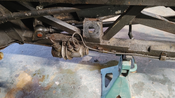
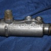
Looks like a non-adjustable brake proportioning valve. Similar to those in the Pantera.
Larry
@lf-tp2511 posted:Looks like a non-adjustable brake proportioning valve. Similar to those in the Pantera.
Larry
Thanks Larry, I thought that was what it is, but going through my archives i haven't seen them on other Mangustas... wasn't sure if it was original or added.
MH
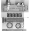
...aka "brake compensator", this one was used on Ferrari (275 or 330?) and also Miura, the bracket seems unique to Mangusta. Mr. Fiat sells a rubber cap ("Miura brake distribution valve rubber cap" over the end, I haven't looked yet for the spring clip. OKP sells a replacement assembly. http://www.miuraworkshop.com/tav25.html
Update Sept 2022; the compensator is being repro'd. even for less than 300 euro. Search Ebay for a Ferrari 250 or Miura regulator (REGOLATORE DI FRENATA, even Fiat 4321182). Expect the threads to NOT be British inch for at least the Fiat AR76 application.
Update Oct 2022; from the Miura website, showing pure metric fittings (but using the Girling ball ends on the lines).
The Pantera version is different, 01310a /b - VALVE ASSY PRESSURE CONTROL . There is a charity/business online that had some repair pieces for Pantera (for just $10, how is that not charity... https://www.musclecarresearch....a-prop-valve-autopsy ) but I have no idea if they work with the Goose piece. See also http://www.panteraplace.com/page199.htm
The clear PVC tubing to cushion the plumbing to the tabs is original.
Attachments
fyi, https://www.ebay.co.uk/itm/194...7:g:Pu4AAOSwbrlc-nEV
....maybe the closest thing available to the bitumen-felt .... 66 euro for shipping from Germany seems like a bargain these days..!
The bitumen-filz was used everywhere on the Goose, at least for interior padding and also on the rear bulkhead. I saw one comment, that bitumen for car interiors has been disallowed (legally) for car interiors, my guess its both toxic and makes a great candle...So closed cell foam is another option...Lee
Attachments
10mm sounds about right. 1.5m x 1m size...
Sad when shipping costs more than the item... They do combine shipping... Anyone else need some?
MH
@mkeh posted:Thanks Larry, I thought that was what it is, but going through my archives i haven't seen them on other Mangustas... wasn't sure if it was original or added.
MH
My car is 8MA888 and it has the same unit. As far as I know the brake system has never been modified. I may be late to the party on this, but here is a shot of me dropping my engine back in. Jackshaft can stay on, but she needs to do a pretty strong "nose dive" to get the required clearance.
Attachments
WOW! Youse guys with the hoist abilities makes me jealous!!! My "breakdown" hoist does not have the abilities of these seen here with the adjustable top arm. So I had to wing it!
Here's my alternative to removing/dropping it all in at once! If you have ceiling clearance issues, or a fixed hoist upper arm, or an uneven work surface (floor!) this could come in handy.
The bellhousing can have issues with the shock tower area, if you cannot get enough vertical lift! That is a LOT of weight swinging around up high at full clearance of all parts involved! The factory photos show a special engine/ZF jig that allows the assembly to be tipped at an extreme nose down attitude such that I believe (could be wrong) that they slipped the engine in with the jackshaft and front pulley in place.
After loosening the front mounts, removing any and all hose connections (fuel and water-radiator & heater hoses), oil & water temp sender unit wiring, taking loose the headers (or completely out), starter, AC pump, and alternator, (smog pump) removed, oil filter removed (may not be necessary if you have a shortie filter installed) and removing the ZF upper rear mount and the shock tower ladder bar, wrap the ZF in straps securely and use your hoist to lift and separate (HAH!) the ZF from the engine.
At this point, the bellhousing and block plate are still potentially able to bugger up the shock tower paint....and require a higher lift. so I simply removed the bellhousing at this point along with the clutch and flywheel after which the block plate comes out as well.
While the nose of the engine is tilted downwards, you should be able to remove the jackshaft front pulley.... it will make engine removal easier.
Now with this stripped down engine, the tilt required to get clearance for the front of the jackshaft should be minimal and lifting the engine out should be a piece of cake once you remove the final nuts or bolts from the engine mounts.
I think that is it, but I reserve the right to forget something!!!
Hopefully this will help someone who is considering doing this job. Even MH when putting his newly restored engine back in place!!!!! Are you done yet?????
I've (unfortunately) had to do this procedure three times, AND I live to tell the tale!!!
Vroom vroom!!!
Steve
Can someone enlighten me too? Please?
"One of my favorite Binky episodes is the most recent one--even after 36 episodes of making brackets... The issue they had with their flex shaft (where the inertia of the accessories was tearing it apart and so they built the clutch function on it) was pretty amazing. Thanks for the tip on that channel so long ago-"


