
A couple weeks ago I found the Jehle Deauville, in what seemed to have been its Tomb over the last couple decades.

As there seem to be very little activity around the Longchamps and Deuville around the web, I figured a "project thread" could serve a purpose. It's also nice to have a log of what has been done to the car.

The car was posted on the local classifieds site (Finn.no), only a few miles of where I live. Having never owned anything Italian, and hardly ever seen a De Tomaso, natural course of action was to go and check out this curiosity.

Deauville - BarnDeauville - barn3Deauville - barn2

Never having been very bright, I bought the car.

310099019_1136850363874414_3800106432341048903_n [1)

20221004_120939 [1)

That's the face of stupid.

310173974_488065403208058_1210456096367104076_n [1)

At this point I did not know much about the car. Deuville or Xaver Jehle.

Attachments

Images (6)
  • Deauville - Barn
  • Deauville - barn3
  • Deauville - barn2
  • 310099019_1136850363874414_3800106432341048903_n (1)
  • 310173974_488065403208058_1210456096367104076_n (1)
  • 20221004_120939 (1)
Last edited by S.Hafsmo
Original Post

Replies sorted oldest to newest

Couple hours drive later, I finally got the car home.

20221004_17394520221004_17400920221004_174016

After a quick rinse it looks like this. I am aware that there are shared opinions with regards to the way the car looks with the Jehle modifications, but I think it looks fantastic. Though I've always loved an oddball.

20221012_15452520221012_15454920221012_15460720221012_15462120221012_154713

I have conversed a little bit with Mr. Jehle himself after acquiring the car (through e-mail and via a few facebook-group members), and he could enlighten me on some of the changes he made to it.

It seems he completely restored the chassis of the vehicle, and replaced all rusty sheet metal. He then re-created the whole bodywork (except roof) in fibreglass. Doors, hood, fenders, rear end - all fibreglass. And as you can see, the trunk lid is made from aluminium. The latter might be stock, but having never seen an original Deauville, I have nothing to compare with.

The new fibreglass body is wider at the front and rear. The change is more discreet in the front, while the rear is based on the Jehle Longchamp flares.


He also found the moulds for the body in his workshop. Still hoping he will find som papers on the car in his archives / office.311041317_627001772299508_7437650670026335294_n

Attachments

Images (9)
  • 20221004_173945
  • 20221004_174009
  • 20221004_174016
  • 20221012_154525
  • 20221012_154549
  • 20221012_154607
  • 20221012_154621
  • 20221012_154713
  • 311041317_627001772299508_7437650670026335294_n
Last edited by S.Hafsmo

Good news!

It is an original Dutch delivered car. The engine number should be 351/173, which should be near the thermostat house on the front of the block. The original colours were Oro Longchamp with a full brown leather interior. First registration was on 30-10-1978 to a private owner.


It left Holland a long time ago. The Dutch DMV go through their books every couple of years for inactive registrations.This one was taken out in 1991, meaning it probably left the country in the late eighties.


I will call my contact who was the service manager for DT in Holland at the time.

He made duplicate records of all DT cars sold and serviced by them and he still has them. All in their own binder, in numerical order stored in filing cabinets. It is quiet amazing that he still has these.


Keep you posted.


Chiel

Steffen

I just wanted to mention that your photos are inserted & attachment boxes collapsed. Thank you for your effort.

If you ever feel you'd like to move this topic (thread) to another forum, such as the "specific De Tomaso photo forum" or the "Longchamp & Deauville tech forum" let me know, its easy for me to do.

Its no longer the Jehle Deauville, its the Hafsmo Deauville. Good luck with your car.

-G

Last edited by George P

George,

I was not certain to where exactly to put such a topic, and the "Longchamp & Deauville tech" may very well be a better place. I couldn't find any similar car-restoration-blog topics.

I am hoping to fill this topic with fault findings and repairs as I progress through them, as well as asking technical questions.

And thank you. Luck will most certainly be needed.

Had to look for a while to find out where the fuel pumps were located. Not a setup I am familiar with.

They don't exacly look brand new, but seem to be operational. New seals and filters have been ordered.

20221023_203455

20221023_20342920221023_203601

Brake calipers I assume will need new rubber, and I am expecting rusty pistons. I've seen caliper repair kits on E-bay which also state stainless pistons. Anyone familiar with these kits?

318328

20221015_210135

Brake master cylinder has internal leakage. Repair kit for Ferrari 328 has been ordered, and I'll post here if it fits / fixes the issue. The orignal metal cap didn't look great, but I see there are replacements available out there.

20221018_190419A20221018_190422

Apologies for the lack of cleanliness. I've got kids, so I must prioritize when I'm in the garage. At least I found what seems to be the wiper motor? Also a setup I've never seen before.

20221015_210123

New seals ordered for the engine. When time allows it I'll do an internal inspection of this lump of metal. I assume the odds of finding closed chamber heads are close to 0 on a '78?

20221015_210653Leaking main seal?

Rack seems to be ok, but ofcourse, I have never driven the car..20221015_210701

Underbelly of the beast. Is it not normal to have hardlines on the fuel supply?

20221016_111936

Attachments

Images (12)
  • 20221023_203429
  • 20221023_203455
  • 20221023_203601
  • 318
  • 328
  • 20221018_190419
  • 20221018_190422
  • 20221015_210123
  • 20221015_210135
  • 20221015_210653
  • 20221015_210701
  • 20221016_111936

Rear parking brake design looks much the same as a Jensen Interceptor Mark111.

There is a place in the UK (Martin Robey) that could probably provide parts (certainly the pads) if they are the same…

A first quick check would be to look at the pads, and verify yours have the tapered friction surfaces that they show on the drawing.

if you’re parking brake it was like mine though, it just needed a lot of cleanup in judicious lubrication.

Hope this helps…

Rocky

The brakes are indeed Girling types used on many late 60s and early 70s Astons.

Also on Lamborghini Espada and Islero and most Maserati from the late sixties.


The fuel line really needs to be hard line with an 8 mm OD.


A straight swap for the master cylinder would be from a late 80s Iveco Dailly truck or Fiat Ducato believe it or not.

The wiper motor is pretty comon. Mostly used on Rover P6 and Triumph Stag.

The fuel pumps look like they have seen better days but hey, if they work why not! Might have to change the filter more often.

I flushed and coated my tanks with POR 15 tank cleaner and tank coating. Great stuff and good security against leaking or crud that keeps coming loose and cloging the filters.

Dutchie; I don't suppose you would have a picture of how such a hardline would be routed?


Fuel pumps will be replaced at some point, but for now they will have to do.

The DB6 brakes seem to be slightly different than the Deauville, utilizing 40 and 57mm pistons, where the Deauville uses 43 and 60mm pistons.

The gas tanks seem to be in decent order, but as a preventive measure I think I'll do the POR 15 tank treatment. Users seem satisfied with the results it gives.

Anyone know of a decent paint shop somewhere in Europe that can be trusted, while not parting me from all my assets?

I saw that (the ebay ad at 57mm vs. the 60mm on Mangusta and apparently on the Deauville as well...with 43mm still for the small ones). The ad mentions they have  2 sizes available...so yeah, I'd just measure up and ask to confirm the set--$100 for the whole set of Stainless pistons and gaskets is a really great deal--Lee

Last edited by leea

The QP-units do indeed look similar.


My progress with the car had to be paused a bit, as the garage needed an upgrade. The purchase of the De Tomaso was not planned, and a bit premature, so its "home" wasn't entirely completed. The presence of a car inside a building under construction does not make completion of the building any easyer.

So, work proceeds in baby-steps. 20221018_20452120221026_220222

As you can see, I am in dire need of storage space, to allow for a clean working environment.

20221016_113941

Other projects had to be re-located.

IMG_20191009_182043

Need to find space for this beast as well. Fresh from the paint booth.

313480093_488167273271965_3533301664678263076_n

Attachments

Images (5)
  • 20221018_204521
  • 20221026_220222
  • 20221016_113941
  • IMG_20191009_182043
  • 313480093_488167273271965_3533301664678263076_n
Last edited by S.Hafsmo

..looks like you are full steam going on it..

just on the Isetta guess 250 ccm or may be 300 ccm if industrial Motor..with all respect you want to finish this as prices are going up like crazy.., if Car would be in Germany I would come by and get it..20k€ and up...

De Tomaso#s are flat after the hyp the last years in Europe (tell me otherwise ..smile)..never mind...I enjoy my GTS Monster.4907..(besides my C2)

matthias

Last edited by matg

Winter is upon us. Getting cold outside these days.

20221117_090418

Work does however continue, even if at a rather slow pace. I am currently going through the ignition and the fuel system. Replacing coils, caps, rotors, sparkplugs, starter relay etc. While doing so I stumble across this unit below the starter relay. Anyone who can tell it's purpose?

20221207_202321

Inside,

20221207_205117


Edit:

From what I can find online, it seems to be the voltage regulator.

Would it make sense to upgrade to a more modern alternator, with integrated voltage regulator?

Attachments

Images (3)
  • 20221117_090418
  • 20221207_205117
  • 20221207_202321
Last edited by S.Hafsmo

..as above...voltage regulator. Looks like an "electronic" device vs old type only per sophisticated relay type as per Bosch in the 6thies (not saying even they are bad.. electronic is prob better to regulate the voltage).

I see NO reason to change, google spec, would guess Alternator current matters! What is in the car? Alternator old type generator.

On this wonderful cars there is more to fix than the regulator ..my 10 cents.

Matthias /Stuttgart Germany

Work continues at reduced pace.

The carb is getting a refurb, and by the looks of it, it was probably due.20230104_183826

Quite a bit of debris in the secondary bowl. 20221216_20355720221216_20554120230108_201743

Choke bimetal spring was broken. Not doing much without the central tab.

20230113_204623

Started going through the electrics as well. Seems to have been a bit of moist in the fuse box, probably coming through a leaky windshield seal.

20221230_215921

Heat has been developing around quite a few fuses, and the fuse box has started to melt.

20221230_215949

The relays also need a bit of TLC.

20230104_18492620230121_215606


The current plan is to replace the entire fuse box / relay board with a more modern system, so if anyone has a wiring diagram for a 78 Deauville that would be much appreciated.

Attachments

Images (9)
  • 20230104_183826
  • 20221216_203557
  • 20221216_205541
  • 20230108_201743
  • 20230113_204623
  • 20221230_215921
  • 20221230_215949
  • 20230104_184926
  • 20230121_215606

My guess is that fuse box is the same as the ones in the Pantera…. There are too few Deauvilles built to come up with a new design.

You may be able to use the Pantera Electronics high-tech fuse box, or if you decide not to get that modern, there is a modified box (I think they came from Pantera Parts Connection in Nevada) that convert to ATO (blade) fuses.  They are a wire-for-wire replacement for the Pantera box.

Rocky

Last edited by rocky

On the fuse box...
Panteras have a fuse box produced out of BAKELIT an early "plastic". It is very hard and does not really melt. I suggest you make a Foto on the fuse side, take them all out, get new once and add one by one back in AFTER a full cleaning of the connectors.  Even a steam cleaner does help besides mechanical of other chemical cleaning. If connection parts corrode the cross resistance will increase hence it start building up "heat". I kept. my old fuse box but added all new fuses. Modern fuse boxes are more reliable as dif fuse design/blade type.

A switch of a fuse box without a full documented wiring diagram is a killer. As you put fuses one by one back see what the fuse controls and COMPARE the result with the very well documented Pantera wireing diagram / see tech pages. AND DOCUMENT every cable !! Use the pantera diagrams to add the color code and wire gauge to it.

The heavy current is related to (so they are the candidates for "burning")
1) Radiator Fans
2) Headlight and motors. you def convert to H4 so heavy current on the ignition swithc!!!
3) Window motors..
4) honk horn!!!  sucks easily 20 amps!  if stuck may be 30 plus

You need to rewire these anyways as all current is running via the ignition switch a BAD resign of the old days. All need to set up via new relays. Existing wires serve just a Relay control signals! So keep all in place!

On the Relay panel well, as above take a foto take one by one out and test it. Panteras have this complex relay for the head light motors, I do not see it in your picture. The old relays are good and reliable but can be replaced by modern once 5 USD China stuff/Hella or Bosch. The old type metal housing type is hard to come by and costly. Relays in general nothing wild, simple on off, active on or active off you need to test it. The numbering on the relay connectors are standard so you can easiy figure out that type of relay you deal with. Also new relays optionally work on sockets so you can build a nice  socket set up. ..and DOCUMENT what you did

Mat

Last edited by matg

As the car will be completly restored, I am considering to remove the entire harness, and create a new one, preferably with a under-hood fuse box in addition to the one in the cabin. Always preferable to to keep relays/fuses close to the heavy consumers.

In my head, the project setup would look something like this,

wireharness

I've been looking at this setup, as it looks quite flexible. If anyone has experiance with other, similar setups, please let me know.

Waterproof Power Distribution Centers

I replaced all the fuses when I inspected the fuse box, as well as cleaned all the contact points. I also removed all the connectors and cleaned their contact surfaces.

20230121_214445

I'll do the same with the relays - open them and clean the internal contact surfaces, but I've noticed that a few of them allow movement of the stationary contacts (pressing on the connectors pushes the contact point upwards inside the relay), which is not ideal.

Attachments

Images (2)
  • 20230121_214445
  • wireharness

Hi Stefen,


There is only 1 wiring diagram for the Deauville and that is the one in the back of the owners manual. This is for series 1 with 12 fuses.

It is mostly the same, lets say 80% usable for our series of Deauville. As far as I know all updates and expansions on the wiring were done as needed and not documented. In fact, the man who made the looms was an outside contractor who was hired as needed. No one, other than him worked on the looms so he had all the knowledge.


I remade most of the wiring in mine with a homemade blade style fusebox.


Nice to see you are making progress! keep it up.

Attachments

Images (2)
  • Fusebox 1
  • fusebox 2

I've been slowly working my way through the wiring diagram, to make a coloured, vector-based diagram with a bit more detail. But I have stumbled upon a couple translation issues.

While I do know most italian colours, I cannot seem to figure out what colour OC refers to?

These also create a bit of confusion; RS and RO (Rosso and Rosa?)

temp. wiring diagram

Attachments

Images (1)
  • temp. wiring diagram

well think I told you to do reverse engineering..start with the Pandera diagrams, they are good and your car is NOT much different in respect of "what goes where". The diagram you posted might be good for an overview but a night mare to really fix the loom.

on color code well I did try Italian restaurants..,, look for an older fellow ..no honestly this did work.

And again USE the PANTERA tech diagrams. All you need is there, as it is a logical view (in Architecture terms)  (shows all needed links without if it is front or rear or any. and it splits it up in "subsystem" level..) this is waht helps you to rebuild the loom not a physical. I did the full loom on my basement table is a peace of hard work and top organization required ..

What I saw from above is right put the loom out AFTER naming all ends to from where they come from. Have a big ply wood or sort of thing add nails in the needed bend corners etc..that will work. I added/replaced app 500 meters of new cable.!  Also as you replace with the CORRECT COLOR you can reduce quite a bit of the cable diameter as modern cable is more Amp "resistant". This helps to make the bending of the loom as it goes back more flexible..

..also as a above RE-ENGINEER head lights and cooler fans..

my 6 cents..happy to help..get you some pictures of my set up later..on a run..

Matthias

Probably a solvent based two-stage laquer.

Mine were peeling also and I refinished the ones on the doors years ago. I still have to do the dash. I used a high quallity single stage boat varnish and brush applied it in 3 or 4 layers. The final coat I did it with a spraygun with diluted varnish. Looks great but slightly lighter in color since I didn't use any pigment in the laquer. For me that looks better with the black leather and silver velours that I have.

Been working on the engine lately and it's now starting to run somewhat properly. It's not that easy to tune an engine when you don't know anything of its condition. I've replaced most of the ignition parts, and mixed/matched a few plug wires to correct deviating resistance measurements.

Anyone care to recommend a set of decent stock+ plug wires?

The old plugs were evenly sooty/wet.

20230219_204626

When checking the compression, most cylinders came out at 125-135 PSI, while cyl. #4 just got 90 PSI. Hopes up for stuck piston rings.

After playing around with the timing / carb tuning, it now starts remarkably well, but seems to need a bit too much timing (~20° BTDC) at idle to run properly. There are naturally also issues with the carb tuning, as it does not seem to wish to idle properly on the idle circuit, and I think I'm partially into the transfer slot.

Should both crank case vents go into the intake manifold to get a correct setup? I currently only have the right bank connected to vacuum, left side vented to atmosphere.

On a side note, The Deauville had to dip its toes in the snow the other day, as the Range Rover needed a couple new ball joints. This came at a less than ideal moment, as I was planning to drive the RR on vacation the next day, and had no charged batteries to start the Deauville.

Have you ever seen a Deauville being towed by a snow blower? Note; belts don't grip on ice. Had to use the other blower with chains to achieve the desired result.

20230318_122406

Attachments

Images (2)
  • 20230219_204626
  • 20230318_122406

Finally got the booster out. Did not go as smoothly as I had hoped. One of the bolts holding the master cylinder to the booster snapped, which increases this part of the project significantly. I did not intend to repair/replace the booster, but looking at what came out of it, a bit of maintenance certainly is due. not sure if I'll fix this one, or get a new unit. They're not very cheap.

I'll fabricate a tool to open it, then we'll see how it looks inside.

20230404_200651

20230410_13523120230410_13523520230410_15061520230410_150624

Attachments

Images (5)
  • 20230410_135231
  • 20230410_135235
  • 20230410_150615
  • 20230410_150624
  • 20230404_200651
Last edited by S.Hafsmo

Project continues at slow pace.

Wiring diagram i somewhat finished. Just got to finish some details regaring the white wires, as they don't show up very well on a white sheet of paper. Nor does any other white paired wire.

I'll probably have to play around a little with line-weights as well, to make the non-horizontal/vertical lines more visible, as anything with a radius or angle tends to look almost transparent when exported to PDF.

*correction, vast improvment by unchecking the "smoothing" setting in Adobe reader.


From Autocad

Attachments

Images (5)
  • mceclip0
  • mceclip1
  • mceclip2
  • mceclip3
  • mceclip4

I found a used, but not complete brake booster from a Ferrari 308 on E-bay, and with a spare in hand I tore into my old unit (and the new one).


First drew up a booster-splitting tool,

Worked like a charm.

On the inside,

The complete unit,

Pushrod removal tool. The push-rod is held in place by a rubber cap, securing a ball joint at the other end. a bit of lubricant in the hole and it pops out. takes a bit of force.

Internals layed out,

Push-rod with spring an poppet valve


Attachments

Images (11)
  • mceclip0
  • mceclip1
  • mceclip2
  • mceclip3
  • mceclip4
  • mceclip5
  • mceclip6
  • mceclip7
  • mceclip8
  • mceclip9
  • mceclip10

Quite a bit of rust in the bottom of my original unit.

The Ebay-unit was however completely immaculate. Rubber diaphragms in both units were in seemingly great condition. Could not see much wear on the sliding surfaces either.

The push-rod is the only part missing from the e-bay unit, so I'll try to have a local machine shop fabricate a new one.

At the end of this, I'll hopefully have 2 operational brake booster units.

Attachments

Images (3)
  • mceclip0
  • mceclip1
  • mceclip2

The brake booster was not the prime suspect of the malfunctioning brake system, as mentioned I initially did not plan to refurbish the booster, only the master sylinder. When one of the bolts securing the master cylinder to the brake booster snapped however, another route was chosen.

If the booster was not operating perfectly before, I would guess the culprit would be the internal sliding surface seal. I'll have a closer look at the old parts before these are discarded (or stored).

The parts kit come from Harmon Classic Brakes, "Booster Major Repair Kit". Item no.: 62-653

Attachments

Images (1)
  • mceclip0

Got the booster back together. The spring pressure is not very hard to overcome, perhaps 40-60kg pressure required. Compressing the new rubber gasket however, requires quite a bit of force.

But as they say, it's when the going gets weird, the weird get going.

I could probably have used the hydraulic press at work, but this was a far more interesting approach.

Brake master cylinder dismantled.

mceclip4

This is where the progress yet again haulted. The repair kit I ordered from "Superperformance" for a Ferrari 308 does not fit. The bore in the Deauville is 1" (25,4mm), while the ferrari parts seem to be 22-23mm.

It seems that the GTB/S has a 1" booster, but so far I've been unable to find seals for one of those.

The used booster for a Ferrari 308 came with a master cylinder, which also has a 1" bore, but the internals are completly different from those in the Deauville. I'll take some comparison photos when I have an opportunity.

Attachments

Images (5)
  • mceclip3
  • mceclip4
  • mceclip5
  • mceclip6
  • mceclip7
Hi Steffen,

Nice construction for reassembly you have there!

I replaced my master cilinder with a 1980s Fiat Ducato unit. It is basically the same except that the rear line connects on the drives side on the master, instead of the passenger side.

For a rebuild kit there is a specialist here in Holland called C&C parts in Baarlo, ccparts.nl. They might be have the correct set.
i ordered their front and rear caliper rebuild kit with stainless steel pistons in the past, from stock and they were great.

Chiel


> Op 09-10-2023 10:45 CEST schreef The De Tomaso Forums <alerts@crowdstack.com>:
>
>
>
>
>

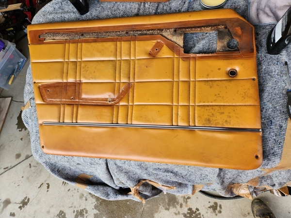
I started dismantling the drivers door doorcard, as this is the one in worst condition. My initial plan was to preserve as much of the original leather as possible, but that may change down the line.

I reached out to Colourlock.no (Car Spa in Norway) for advice regarding the concervation of old leather, as well as the proper method to clean it, without damaging it. The first reply I got was "reupholster. Black mold can't be removed" and thats it. Not a very satisfactory reply, and it does not address the parts of the leather where no mold is present.

I then reached out to their central location in Germany, where I got this recommendation: "use 50/50 water/vinegar to clean the interior" and thats it. No mentioning of their own producs. Which I must say that I find a bit peculiar. They did however shed some more light on why it's hard to remove black mold, with a rather thorough reply;

There is no general answer to whether mold infestation can be eliminated with cleaning and care products alone, or whether a new upholstery including replacement of the upholstery material is necessary and depends on the length of time the leather has been exposed to the unfavorable environmental conditions.

A little mold that appears on vintage car seats after a few months can usually be removed using simple means. However, sets where the mold has spread over several years are rarely available. The reason lies not only in the usually large-scale visible disfigurement of the leather - the entire inner core of the upholstery is usually also covered in mold threads. Even after intensive external processing, any stress on the upholstery, such as sitting on it, causes the effect of a bellows: the mold spores are blown into the interior along with an unpleasant smell.

It is then not a solution to try to overlay the smell with other smells. You then only get a mixture of the perfume used and the smell of mold. The nose is then even more irritated. Such serious cases can only be solved by having the upholstery core and leather completely replaced by a saddler. In this case, the upholstery core cannot be satisfactorily washed or recycled, which would not be of any financial advantage anyway: the leather has already been removed and a new upholstery core hardly increases the costs, but in fact usually improves the seating comfort considerably.

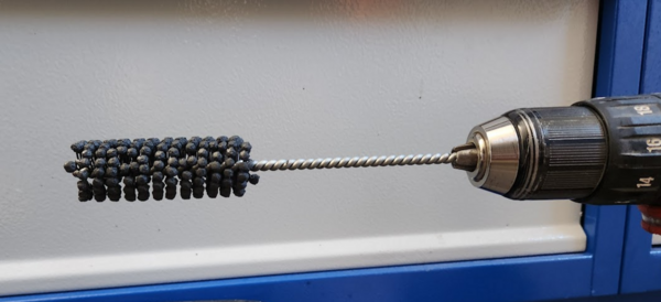
Basically, what I hear is "use the damaged parts to practice leather re-colouring". So that is what I will do. First I have to figure out what colour to use, as I actually prefer the lighter tan/faded brown to the original dark brown leather.

The back side of the door card with vapour barrier in place.

mceclip0

mceclip1

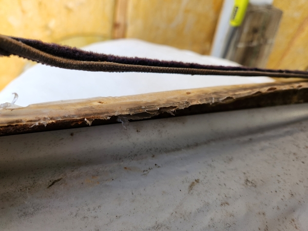
Window seal/strip. Is the rubber gone, or are these just fabric from the factory?

The black strips cover the bolts holding the arm rest/door handle.

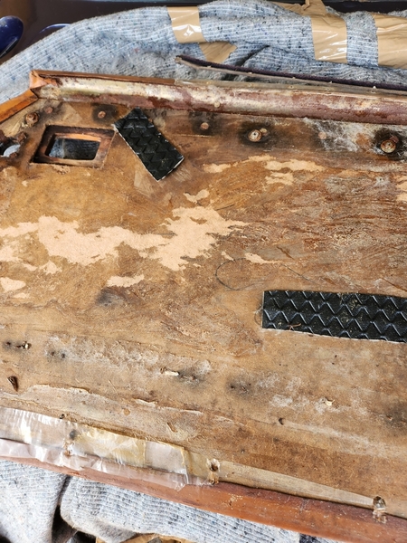
You almost can't tell that the exposed leather has faded. The remaining dark spots from the mold seem to be a permanent discolouration. It will be interesting to see what a respray will do.

Reupholstering parts of the interior is probably unavoidable, but that can be done at a later stage.

Attachments

Images (5)
  • mceclip0
  • mceclip1
  • mceclip2
  • mceclip3
  • mceclip4
Last edited by S.Hafsmo

There is no rubber seal in between. Just the fabric strip against the doorcard.

it is a very strong discolouring. Almost looks as if it has been redyed in tan in the past without removing the armrest etc. I have seen a few interior colours from partly dsimantled Deauvilles and Longchamps and the diffrence in colour was marginal, far less than  instance the mousehair dashtops which far more prone to fading.

The leather dyeing back then was still nitro cellulose based an far more durable than the current water based.

I know it came with brown leather from the factory but there is only one that I know which is called Testa di Moro. That is a dark bitter chocolate colour.

Who knows, maybe they had a medium brown option also.

@dutchie2 posted:
For a rebuild kit there is a specialist here in Holland called C&C parts in Baarlo, ccparts.nl. They might be have the correct set.
Chiel
Your advice did indeed pay off. C&C parts can provide.
Thanks Chiel!
I've also acquired a hone for the master cylinder. Mostly to satisfy my curiosity, and to reveal its true condition.
Before,
After,
There are still a bit of pitting in the bore, but I did not want to take out more material. I am however certain that most of the burrs/scratches are removed, and therefore won't rip the new seals.
The hone,
The external surface is also getting a refresh, and this finally gave me an opportunity to test "Evaporust", and I must say, I am impressed. Ofcourse I did non purchase enough to submerge the whole unit, but you can probably guess which part of it got to dive first.
Prior to this the part was scraped and cleaned with a wire brush. The remaining rust was quite stubborn.

Attachments

Images (6)
  • mceclip0
  • mceclip1
  • mceclip2
  • mceclip3
  • mceclip4
  • mceclip5

Black friday happened, and I bought a new tool (not the Lego Ferrari).

It's an Einstar 3D scanner, which I'll attempt to use to design new headlight surrounds, as my car currently has none.

So I've scanned the front of the car, and quickly realised that it is fare more amusing to create some sort of a GTS-like lip, just to see how it would look. Turns out, designing things that look good, is hard. And I am not very good at it.

I was trying to recreate the shape of the Pantera GT5-S, but I need to scan the whole car to get a proper impression of how it would look.

In the end I will probably end up trying to replicate the stock (?) lip, or something similar.

Attachments

Images (4)
  • mceclip0
  • mceclip1
  • mceclip2
  • mceclip3

That is a really cool tool, that scanner!

Nice to hear that C&C came through on the brake parts. I bead blasted the callipers myself and painted them with a 2-pack paint and clear laquer. They look like new.

I have an extra set of used original headlight surrounds. I know the Jehle front is altered from the original so I don.t know if they are of any use to you.

Let me know if you think you might be abled to use them.


Chiel

@dutchie2 posted:

However, the pitting is at the point where the piston rests in the cylinder,

That is a very valid point. I'll check the condition of the Ferrari 308 master cylinder.

I don't suppose anyone would remember how the small springs were located within the assembly? My "before" picture seem to have disappeared, and however I place them, they don't seem to have a proper surface to push against.

IMG_20231229_143714111

Attachments

Images (1)
  • IMG_20231229_143714111

This is the contents of the Ferrari 308 GTB/GTS master cylinder.

It's similar, but certainly not the same. The seal mounts and spring guides are different, and they lack the slimmer, secondary spring.

Seal assembly,

The bore of the master cylinder does however seem to be in good condition, and not pitted like mine.

I also did a closer inspection on the original MC, and it seems that I cannot install it in this order,

As the inner piston would hit the end cap and thus not allow proper movement. The inner piston also has a slot for a flat head scewdriver to help align the piston slot to the set screw, which I seem to remember was accessible when the end cap was removed.

Edit: My memory is, as usual, a poor source of information. The inner piston must indeed be positioned as in the above photo, as the adapter plate between the springs will seize on the larger diameter of the protrusion with the slotted head. It seems that the thinner springs purpose is to put pressure on the D-ring seal. The Ferrari 308 seals have a different arrangement to ensure spring pressure on the seals (see separate post below).

The pittings in the old bore were also on the opposite side of the master cylinder, so it could probably be used with the risk of some internal leakage.


To ad a bit confusion to these last post, Here's the content of the brake pressure differential valve, which you can read about here, GROUP 2B527 - Brake Pressure Differential Valve

I've ordered a spare part kit for it. We'll see if anything fits.

1970+ Ford Disc/Drum Brake Pressure Differential Switch Kit

Attachments

Images (7)
  • mceclip0
  • mceclip1
  • mceclip2
  • mceclip3
  • mceclip4
  • mceclip5
  • mceclip6
Last edited by S.Hafsmo

I did a conversion from hydraulic to an electric brakelight switch. Any 1980s or 1990s Volvo 700 series switch does the job perfectly. I made a bracket to mount it behind the brake pedal and used the original wiring pulled back through the firewall. No modifying other crimping on new connectors.

I can make some pictures of it if you need them.


Chiel

google Ford  brake pressure differential switch Ebay motors.usa.

replacements available for $20-$30.

those plastic switch is leaking when the inner O rings are leaking.

the plastic switch dont protect you for leaking.

when this is leaking it's hard to see , but you notice when the trunck floor is wet from brake fluid.

you also can close this hole ,or delete the complete bronze switch, that protect you from troubles and brake fluid leaking.

Simon

Christmas gift to self. Those are always the best.

This was built as a spare engine to a street/strip 69 mustang, but the owner realised he had too many projects, and sold it. He built two 351Cs of the same recipe, and the other put down around 485 crank hp. I chose to not have this one dynoed, as I recon there are better ways to part with $1000.

What's interesting is that these builds sport the supposedly woeful 2V open chamber heads. Heads are ported, adjustable rockers (machined), domed pistons .030 over (10.5:1 static comp), Weiand X-CELerator intake etc.

In its current iteration is has not been broken in, so before installing it in the car, I'll do some checks just to confirm piston to valve clearance, rocker geometry, bearing clearances, timing chain, etc.

Attachments

Images (1)
  • mceclip0

Was hoping to put the brakes back together in order to do a function test on all the parts I've worked on so far. This is ofcourse not the correct course of action, as I have not done the calipers yet, but a lack of patiens and an urgent wish to finally drive the car gets the best of me..

Differential switch valve block looks better now. The parts from Muscelcarresearch fit as supposed.

20240128_135953

Cleaned up and assembled the master cylinder with floats.

20240316_140620

Still fits in the car. Made new cunifer brake lines, but will need to re-rout them when I take the engine out.

20240317_142852

The old pipes had bubble flares on the brake master side, and single flare towards the brake switch block. As far as I am aware, the single flares are only recommende for use in low pressure system (fuel lines etc.) as they are prone to cracking in the flare, causing leaks.

Bubble flare

20240317_150149

Single flare. I replaced these with double flares.

20240317_150156

Now, with all brake parts back in the car, time to bleed the brakes and see if it all still works.

20240401_115804

Or not.

Bleed screw broke off with minimal effort. Which is great.. Time to overhaul the calipers.

20240401_115809

I tried to remove the crossover pipe in order to evacuate the fresh brake fluid, but the hose going to the wheel seem to have swollen inside to such an extent, not a single drop would reach the caliper. Upon removal of the crossover pipe however, the pressure already present in the caliper was released, which explains why this car has been less than easy to move around. The rotor now spins freely (which revealed a bad wheel bearing).

20240402_192136

Fire is always useful.

20240402_192816

While I do posess the parts needed to remanufacture the brake caliperes (if the bores are salvageable), I can't seem to find any good information on the wheel bearings this car uses. If anyone knows, please advice.

20240402_181804

It's a rather interesting hub-setup, and doesn't look like the Pantera setup. Is it the same on the Longchamp? Maserati QP?

Attachments

Images (10)
  • 20240316_140620
  • 20240317_142852
  • 20240401_115804
  • 20240401_115809
  • 20240402_181804
  • 20240402_192136
  • 20240402_192816
  • 20240128_135953
  • 20240317_150149
  • 20240317_150156
Last edited by S.Hafsmo

The bearings are used on most Maseratis from the late 1960s onwards. I don't have the numbers on the outer shells and inner racers. Maseratinet.com sells them for sure.

I did replace the rear ones in the past. I gave the numbers on the inner and outer bearing to a supplier here in Amsterdam and they ordered them for me from Timken. Same story for the seals. A local supplier had them on stock.


That broken bleed screw is always painfull! One of those live and learn experiences I guess. Believe me, I have been there!

Now, when working on dodgy callipers, I always start with applying heat to the bleed screw and making shure it frees up.

I was aware that the shortcut I was pursuing probably would end up with something like this happening. All remaining pipe connections needed a bit of heat to let go. Removing the leftover bleed screw should not provide much of a problem.

Does your front hubs look similar to mine? Just want to make sure nobody has been modifying anything before I start ordering parts, and I couldn't find any decent photos of a stock Deauville or Longchamp front hub.

Add Reply

Post
×
×
×
×
Link copied to your clipboard.
×