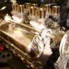
Alright, back to it! Spent the last couple of days side tracked on a 68 Shelby tilt column rebuild...was a small challenge....make one good column out of two bad ones please! It is packed and ready to ship....back to the engine!

I just looked at the date I took these pictures and it was almost exactly 25 months ago. I started on the rebuild way before I started dissassembly. Of course never anticipating a one year side track! Should have known...it's a Goose! Smiler


Follow along, this is "almost a long block" in around 20 pictures...and 10 minutes!

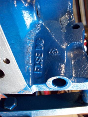
My core block, from a 92 T-bird IIRC.
 

Bought a complete engine and pretty much discarded everything but the block....sold off the EFI intake etc, heads....

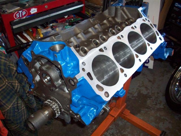
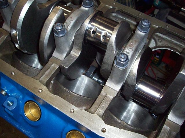
I had it bored +.030 and it needed a slight amount of decking on the top of the bores to align the decks properly. (Found this when I was checking installed piston height!) Here the crank is already in as well as the new E303 Ford roller cam.
 

Nice machine work on the crank oiling holes!
 

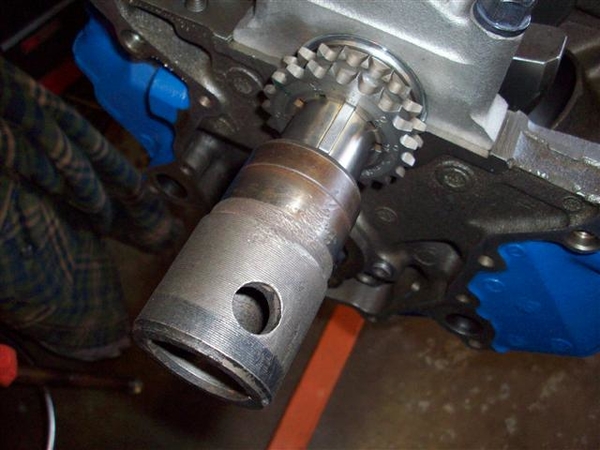
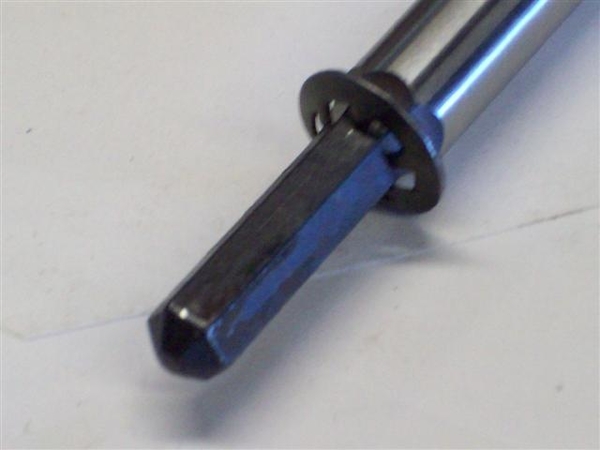
Here is a crank spinning tool I made from an old Ford 352/390/410/427/428 harmonic balancer spacer. Drilled a cross hole in it large enuf for my big screwdriver or a lug wrench and voila! New tool! ...for cheap! Slips right on and off!
 

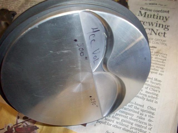
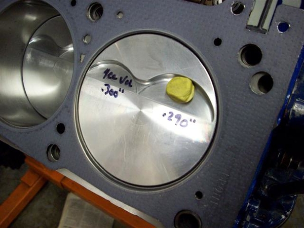
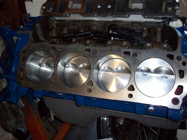
Closeup of a piston. Had to really dig to get a flat top piston with only two valve reliefs! Four would have cut down my compression ratio. I am aiming for about a 10.3:1 if my calculator did the calculations I wanted it to do.....correctly!
 
I polished or smoothed the edges of the reliefs to lessen chance of detonation on a sharp edge! Used a machinist's deburring tool followed up with some 320 or 400 wet/dry sand paper, maybe followed up with some 600....can't quite recall.

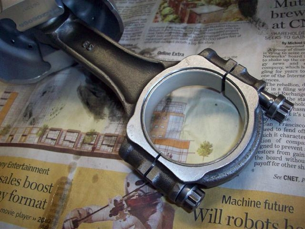
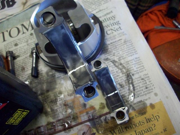
New I-beam rods with 12pt cap screws. I would have liked H-beams like I have already, but in this case, they would only be effective for bragging rights! (6500 absolute max RPM self imposed limit due to jackshaft...)
 

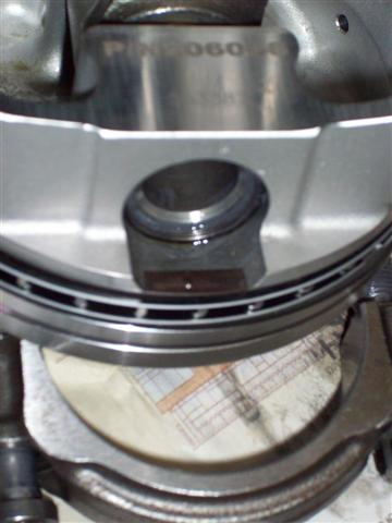
Spirolocks....hmmmm. First time messing with these little buggers!!! Two on each side of the pin.....
 

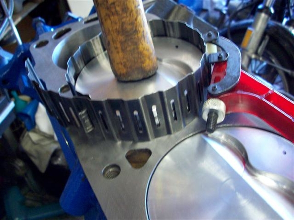
In goes a piston.
 

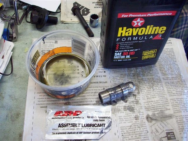
Slight mixture of molylube and oil for the bearings before tapping the piston into position.
 

New ARP or so, HD oil pump driveshaft.
 

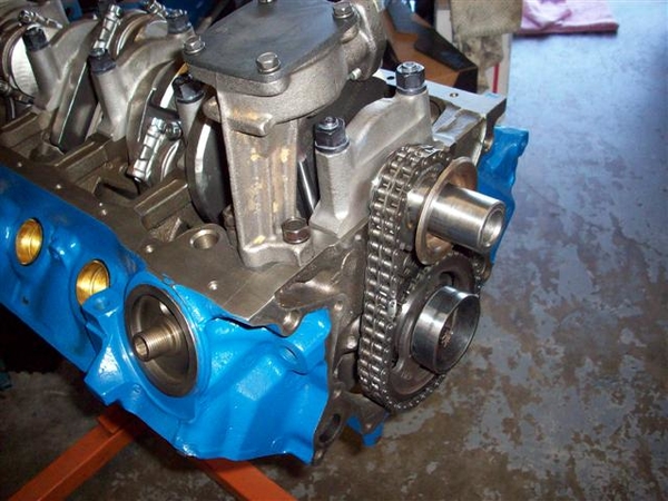
New Ford double roller adjustable timing set and high volume oil pump. (NOT high pressure)
 

Lubed up the new roller lifters with more of the same mixture of moly and oil.
 

Checking piston to valve clearance. Running 1.7 rockers to get a tad more lift than the stock 1.6's.
 

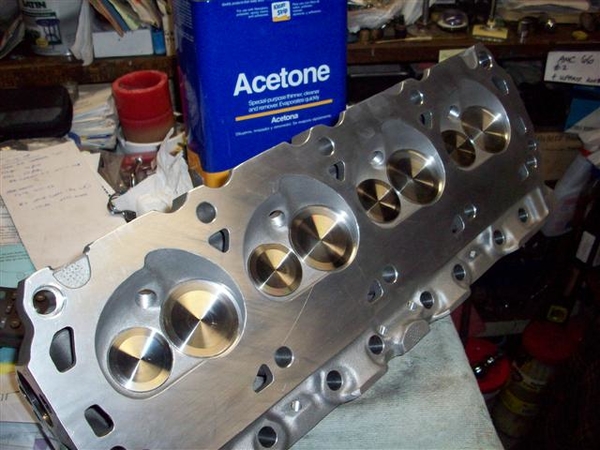
New heads, Motorsports Y303 heads. Tall intake port, no longer available, replaced by X and Z series heads. These have a little more sealing materials around the tops of the intake ports....when the Motorsports tech guy said that he'd seen some cases of intake gaskets failing at the tops of the ports, it helped me with my decision! Mo' meat please!
 
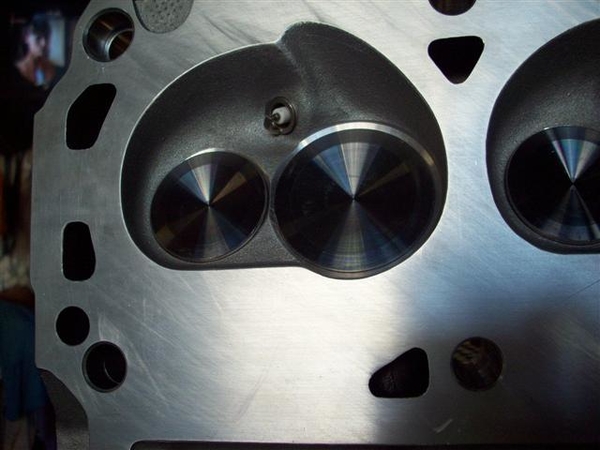
I also smoothed the sharp edges on the chambers too. These are fairly large chambers...64-65cc IIRC. Will see what I find in my notes.....

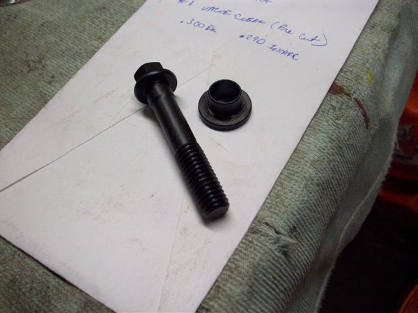
Since these are Motorsports heads, they are cut for a 1/2" head bolt (351), so spacers are required to install them on the 302 blocks.
 

Close up of the chamber and valve work.
 
NB: Need to install spark plug indexing washers and mark plugs yet!

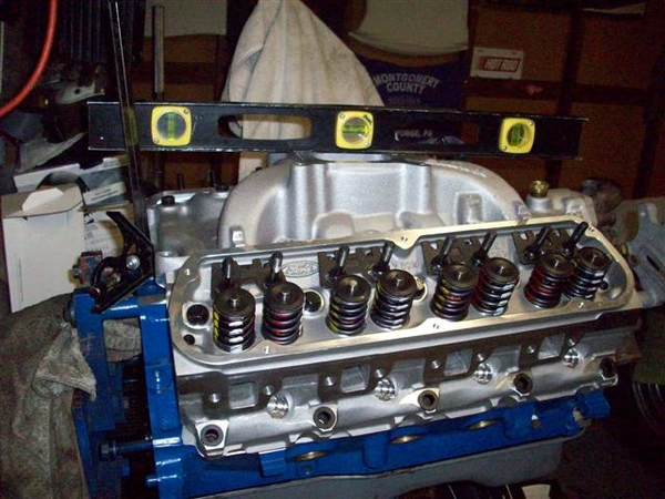
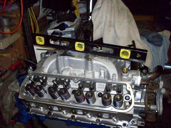
This is about where it sits right now, with heads on with only a couple of bolts, so until I can get intake manifold fitting sorted out....
 
5.0L oil pan is just to keep it clean. Also stored inside a large plastic bag!

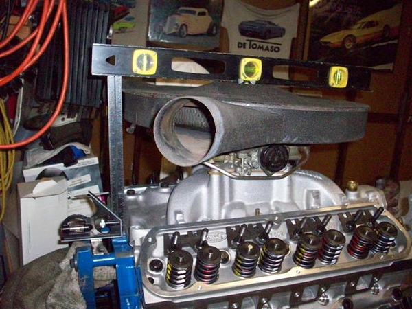
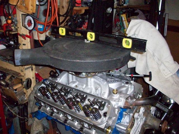
Some shots while checking out the Performer RPM for air cleaner height.

First some checks (to deck, front and rear) for comparison against a regular Performer 289 that I had specially modified for the tall port Y303 heads. (I'm leaning towards the RPM now that my chassis engine mounts are now at the correct height!!! ....but the Performer would allow me to raise the engine back up a tad.....ugh!)


Now with carb and air cleaner (no carb spacers or gaskets)


That's about where I am.

Tonight I spent comparing and measuring for the jackshaft bracket and the two idler pulley mounting brackets.

I have all three in NOS form, and none of them fit properly. While the idler brackets are flat on the front side, where they attach to the water pump, they have gaps or are machined crooked!!! I also need to lower the main jackshaft bracket about .200" to get it to line up with the holes in the front support properly!

I'm making my list to take to the machinist....

* also need to cut a new pilot bushing for the trans....or ream the one I have out ever so slightly.

Next? More of the same...lots of staring, putting on a part, taking it off. Put on a different part or two....take them back off......

I guess I can say that it is hand built without lying!

Cheers!
Steve

Attachments

Images (25)
  • blobid0
  • blobid1
  • blobid2
  • blobid3
  • blobid4
  • blobid5
  • blobid6
  • blobid7
  • blobid8
  • blobid9
  • blobid10
  • blobid11
  • blobid12
  • blobid13
  • blobid14
  • blobid15
  • blobid16
  • blobid17
  • blobid18
  • blobid19
  • blobid20
  • blobid21
  • blobid22
  • blobid23
  • blobid24
Last edited by mangusta

Tonight I was determined to start porting on the new intake manifold...but which intake??? Dug back into my pile of notes, and found my measurements with various intakes and stock air cleaner, measured from the front and rear deck surfaces of the block to a line thru the top center surface of the air cleaner (center is taller than the edges by a bit due to the shape).

I have a choice of the Performer or the Performer RPM. Last night, I determined that the taller (+5/8") carb flange of the RPM would be desired as less cutting on the center bearing support of the jackshaft bracket would be needed to allow me to run an automatic choke! Something I have been sorely missing! If I had to run the shorter Performer, I would be required to run a manual choke and a cable...not too big a deal....but I like automatic....! Have grown fond of the feature you may say....

From my old notes, I determined that the RPM will fit, as it is within 1/4" of the height when using the original cast iron intake manifold and stock 1" spacer! I reasoned that I have dropped my engine mounts (chassis side) by 1 5/8"), increased my rubber mount thickness by about 3/4", so it should leave me in the neighborhood of 7/8" to allow a 1/4" phenolic carb spacer and proper gaskets. AND, I may even get REAL lucky and be able to put in 1/2" shims to raise the engine back up a tad to give my expensive oil pan some room to get out of the driveway!! Hey, at this point, if I can get away with 3/8" shims, I will still be a happy man!

Previously, I had already scribed marks on the intake ports to use as a guide.
 

These marks are out to the extreme of the gaskets, which were made to fit a number of Ford small block aluminum heads. They are Felpro gaskets, but nothing you can buy over the counter...go figure! OEM (Ford Motorsports) only! So, I've been buying up a few sets when they pop up on ebay when dealers are closing them out! There are other gaskets made that will now work, Edelbrock and others have similar that will do the trick. In my case, I do not want to take out all the material to the lines. I need to leave about 3/32-1/8" as the ports are almost right...but the tops and bottoms of the ports can use some work, and then straightening on the sides a bit.

SO, out to the garage to start porting....dug out the porting kit I bought from Standard Abrasives, and scanned the directions.... "go easy on aluminum" seems to be the mantra....AND you need a 1/4" die-grinder, air or electric..........something I failed to purchase! Hmm, too late to hit Home Depot tools....so on to something else....

Here are some other manifold mods....did most of the measuring last night but didn't mention it.
Last year or so I was checking this all out and I removed some casting material from the first and second bolt holes on the RH side to allow the jackshaft bracket to sit properly. I will be lowering the bracket by .200" also..more in a few! Will probably now need to remove even more material!
 

At the rear of the stock intake, there was a boss about 3" in from the RH side of the intake. The original jackshaft bracket bolted to a hole here for additional support. I hope to make up a piece and have it heliarced in place to allow this support to be utilized.
 

My jackshaft bracket is a new unit that I picked up in Italy on a business trip that allowed me the opportunity to visit the factory! This was back in about 96. So far, very few of my NOS pieces that I picked up from the factory have actually fit with out some sort of needed tweeking or major difference from the old part! Testament to the fact that these cars are "moving targets" when you are trying to get parts to fit properly, from the vendors!!! ...or anywhere else!

In comparing my original bracket to the new one, the new stands are aprox .200" too tall.
 

Lowering it this much will allow the front support bolt holes to line up properly. The front surface of the jackshaft bracket was originally fly cut straight across where the front bracket attaches. The new one has been spot faced...and now has material in the way of the two pieces mating properly.....so that will need to be addressed also.

In addition to these differences, the size of the rear shaft bearing is also larger!!! Already purchased new bearing in the proper size...now have extras of the old ones!

I also bought both idler pulley brackets new from DeTomaso. The original RH unit I have looks like someone went after it with a hammer, shattered it in three pieces, and someone welded it all back together with large pieces of gum! Makes me wonder if I shouldn't have this new one reinforced too!

 
While the jackshaft bracket machining seemed straight, the work on this piece was anything but! These two nearest bosses are not flat and are not at the same height relationship to fit properly on the water pump bosses to allow it to sit properly to meet up with the jackshaft bracket front two support bolts. It's totally a Goose thing, if you are a Pantera owner scratching your head....

I will have .070" taken off of the small boss, and the long one "flattened" or made parallel to the front bosses....all of which appear to be level with each other when placed on a super flat surface!

My original LH idler bracket is in great shape for some reason, so I will re-use it. The new one I picked up seems like it will do the job as well but could need some machining.... I will test everything with the Edelbrock water pump that I swap off of my old engine before passing final judgement. I am using a 1973 water pump (D3TE Ford casting)for mockup, and found some slight fitment issues when I dug out an original 1968-69 Ford pump casting! The idler bracket fits that older casting very well!!! The early pump was still on a family car driving around.....last time I worked on all of this, so wasn't readily available for test fits!!! Smiler

Now I know it is a good part to have around! I had been wondering what to do with it...scrap pile or.....?

Maybe that will be a good thing for this weekend.....swap remaining parts off of the old engine....pulleys, install fuel pump and water pump, align at least the LH idler pulley properly. RH will need to be done after the machining is complete.

It probably took me longer to describe all of this than it took for me to get to the point this evening where I needed more power tools to go further. In order to move the entire project forward, I dug out the halfshafts and got them ready to roll!


I installed a new cork seal in each and greased up the splines. I also lubed the u-joints. They took a rather disturbing amount of grease....which makes me wonder if they were ever greased ?! I must have given them a few shots the first time this was all apart, as I remember shooting grease out the air hole of the splined inner half shaft...and having to clean it off of everything after a drive..... The splined slip joint portion of the shaft does not hold much grease to keep the splines happy!!! As for the u-joints...maybe I missed it! All 4 of them??????

Tomorrow: shop for new air tool and grind away!

Out!
Steve

Attachments

Images (6)
  • blobid0
  • blobid1
  • blobid2
  • blobid3
  • blobid4
  • blobid5
Last edited by mangusta

This last weekend was a good weekend of small progresses....

Buddy had a die grinder, so just borrowed it instead of buying one.....

With about 2-3 hours, I ended up with this:
 

But what you really want to see is this!


Remember, I never intended to take the grinding out to the scribe marks. They are the gasket size, but not the port size of the head....

While the heads were still loose, I installed spark plugs and "indexed" them, so that the electrode is not shrouding the spark. I used indexing washers, which are various thicknesses, to cause the electrode to land in a different spot when tightened down.

Installed and torqued down the heads. Whoo hoo!
These Y303 heads are made for 351's and have the large 1/2" head bolt holes. Since the 302 takes smaller bolts, I had to purchase special shimmed washers to take up the space. (Ford used to have special stepped bolts....but no longer....you get washers!)

Received my new Swage-lock fitting and installed it today after bending the line to clear the motor mount properly.
 

Removed many components off of the old motor. All that remains is to claim the oil pan! Need to eat my wheaties.....and get the long block up on an engine stand to do so...then give it a quick bath in parts solvent. Maybe later this week after it rains...big storm a comin'!

Spent a LOT of time on the jackshaft brackets and alignment. Ran my (new)brackets down to a local Mustang shop which has a small machine shop and the guy to run them...!!! In just short of two hours, I had a .200" shorter jackshaft bracket as we cut down the 4 mounting towers, spotfaced the front mounting surface so that it will mate properly with the front support bracket, a support bracket that was altered very slightly as well to fit better.

I played around with various shims and washers and got the belts to align to the point where they shouldn't go flying off at high RPM's! I have yet to mount the actual jackshaft and it's bearings etc, so will probably need to do some more work to line the front (and rear!) pulley up!!!

I'll need a new small belt (idler only) due to changes in where the idler bracket mounted... and probably a new belt for the jackshaft...we'll see!

Here is a shot with the water pump mounted, fuel pump, oil sender, harmonic balancer is torqued down, and crank pulley is installed. This shows the relationship of the idler pulleys and their mounting brackets nicely.


I may need to dredge up on of those spacers that you find for the nose of the water pump. DeTomaso cut a 3/4" hole in the pulley and the shaft is 5/8"....could be mounted off center easily! I think their first motors may have been industrial types....which supposedly use the larger shaft size! I know I saw one of these spacers not that long ago, perhaps last water pump job we did here.....but I have no idea what the heck I did with that spacer!!!! AP store will have one..... Didn't need it before, but just in case the bolts don't center it properly, I don't want a vibration....for a $1 cure!

These pulleys, water pump and crank, are special units cast up by a vendor for DeTomaso. Although some of your cars will have a stock Ford Crank pulley, found on some early Mustangs (1965-1966), it will most likely have a DeTomaso version of a water pump pulley on it, as Ford never produced a two sheave water pump pulley with one small and one large belt (width)....just the crank pulley! I dug through the Ford parts books and could not find a stock pulley which would do the job! Not made by them!!!

Tonight, I spent time aligning the pushrod guide plates. I had a set of Motorsports guide plates, but they seemed a little on the weak side and they really didn't allow fine tuning of the rocker arm position!
Here is a shot with a Motorsports fixed version on the left and the unnamed adjustable units on the right. Once they are in position, you are supposed to tack weld them together so that they don't shift when you torque the studs down! That will be interesting!


One thing that I have not yet figured out yet, is the oil dipstick. I would love to use this version here.... from a 91-92 T-Bird and probably a few others!
 

It could go on the RH side in the stock location but I want to bend it back some more to get out of the way of the coil and front hinged cover, so it is easy to get at when filling up with gas.

Something like this, only bent back more...
 

If that isn't going to work, then put it on the LH side but instead of curving towards the front of the engine, swing it 180 degrees towards the rear. Need to figure out if the AC compressor will be in the way there, or perhaps the paper tube for the air cleaner, or even the water tank! We'll see!


That's it folks!

Shopping list:
Various bolts, washers, lock washers.
Water pump shaft spacer
Belt(s)
Lower hose for water pump
1/4-3/8" carb spacer. More choke clearance!!! Almost there!

Research:
Colors on distributor gears for roller cams. New gear I have has yellow paint on it. Distributor that is from a roller motor...has orange paint on it.....not sure who is telling the truth! Could be both are good!

Valve cover spacers...did I forget to mention that my whippy dippy late model "powered by Ford" aluminum valve covers will not fit with the adjustable roller rockers installed???? UGh!

Always something!
Ciao!
Steve

Attachments

Images (8)
  • blobid0
  • blobid1
  • blobid2
  • blobid3
  • blobid4
  • blobid5
  • blobid6
  • blobid7
Last edited by mangusta
quote:
Ford never produced a two sheave water pump pulley with one small and one large belt (width).

Would love to see a picture of that pulley from the top looking down onto the sheaves. My 66 GT Mustang has a 2 sheave water pump pulley, but both sheaves are the same size I believe.
quote:
One thing that I have not yet figured out yet, is the oil dipstick. I would love to use this version here.... from a 91-92 T-Bird and probably a few others!

If you need a longer dipstick, you could use one from a 1990 Ford Econoline Van that had the 351W engine. Trevor used one on the 392W crate engine in his Pantera.
Ford Motor Company part numbers:
Dipstick: F2UZ-6750-B
Tube: F5UZ-6754-B

Attachments

Images (1)
  • dipstick_90-Ford-Econoline_1-sm
Garth,

Thanks for the shot of the Econoline setup! I know I have seen them......just forgot about them!

As for that pesky pulley, nope. Ford never made one with the small sheave in the rear, and the larger sheave in the front.

The reason that they do have a crank pulley that fits is due to power steering cars. They used the larger 1/2" belt on the pump, but it was driven directly from the crank pulley and didn't go 'round the water pump!

In later years, the sheave on the P/S pump went smaller as Ford started using smaller width belts depending on application....

It's always something.....

Steve

Well, here we are mid week, wondering if I went forwards or backwards!!!?

Some updates:
Distributor gears: orange is for a flat tappet cammed 302...ugh. Just what I don't need! Not what I was sold either....this "had been in a roller cam motor..." Yah, may have been in it, but wasn't correct!

It is in great shape, very little use on it, so will go in the spare pile for spare 302 parts...non-5.0L parts!

Yellow paint: AHAH...for a 302...and a 351W....hmmm. This won't fit either....in the early 90's or late 80's.... Ford decided to use the same gear for both engines...seems logical! That made the shaft diameter grow to about .530" from .470 or so.... Another part for the "spares" pile!!! But it will work for the old 351W if I ever get around to that project.....ugh.

Ordered a new gear off of ebay...we'll see what happens.

Tore down the distributor and am working on learning about advance curves etc.

All it really did is make me wonder about "what is the more ideal magic approximation" of a max timing figure? I had always thought 34-36 degrees but that may just be for the Clevelands.....and we're talking 302 here.... What was odd, is that the mechanical advance mechanism under the "breaker plate" had the stop set up in the "21L" slot, allowing it to advance a whopping 42 degrees! (2x the stamped number= advance degrees.) Add in 4 degrees of static or initial timing and you've got a whole lot of timing! I guess the old 80's non-roller, non-efi engines were pigs with low compression.....

Again, will need to do a little more research on timing max value and a curve. I understand that both are a matter of how much compression you have......and of course...fuel quality....

Pulled the old gear off of the distributor tonight and put all the bits away for later reconstruction!

Carb Gasket/spacer: Found an Edelbrock #9266 extra thick gasket (.320") with four longer carb studs in Summit's stuff on ebay. About $20 shipped... Would cost me at least $5 in driving around.....I'll let the UPS or FedEx guy deliver...will give the dog something to get excited about.....

Hoses: Trying to figure out what I bought for a lower water pump hose....I thought I may have borrowed it from my stock of 68 Cougar parts....we'll see!

Worked more on the fitment of the jackshaft bracket to the intake. I want to have a rear support boss welded onto the intake....so cut up a mock piece out of some firewood.... then found a piece of aluminum....but need to shave it down with a mill to .352" thick and then had file it to fit the contour of the intake runner.... It shouldn't take much stress...just act as a support for the jackshaft bracket to keep it from rocking.

Looked at jackshaft bearings and how to get them on and off..... THIS is going to be a real PITA!

I have a puller for getting bearings off..but this really only works well for the end bearings. (I will need to get more threaded rod....for doing the middle bearing!) I believe this is an OTC (Owatonna Tool Co) puller that I got either off of ebay or from Harbor Freight....


I had put the new bearings on the shaft earlier.....in anticipation that this would be fairly straightforward and easy! HAH! What was I smoking????

Stopped by Home Depot on the way home from work and snagged a 3ft piece of 3/8" threaded rod, a 5" length of 1" black pipe (only because they didn't have an 18" piece of it!...), and one more can of silver paint to do the trans crossmember in.... (Threaded rod to pull bearings thru bores to make it "not like the first time" when doing final assembly, and the 1" black pipe is for "tapping" the rear bearing on if need be...

Since my jackshaft bracket was new, I did some deburring of the inner bores and around where the snap ring grooves were cut. I then used the threaded rod and any number of round things with a minimum of a 3/8" hole thru them to act as pushing or pulling bits to help move a bearing through a hole! I even put an old throw out bearing to good use!


I put a small amount of anti-seize in the bores and slowly applied pressure to the nuts on the threaded rod. Starting with the center bore hole I got about 70% thru and it stopped. Since the bracket was not bolted down to anything, I saw that the front section of the bracket was starting to bend under the pressure.

I would need to fabricate long spacers to put in between the bearing bosses at the top, to prevent the bracket from bending towards the un-cast side. I stopped, reversed the pile of adapting parts, and pulled the bearing out. Did a little more deburring, polished it up with some worn 320 wet/dry paper, put in more anti-seize, and this time pulled the bearing through with little opposition! Wiped off the mess I made with the anti-seize and pulled the bearing through again!

Repeated the process with the front bearing and also the rear bearing. I have a pic I'll post later of the polished finish that resulted!

Here is a pic of the rear most bearing area after pulling the new bearing through twice. Nice and polished!


A quick check of the parts book to look for bolts (more in a bit) and found that there are three different versions of jackshaft bracket! This is a later version, that has a 52mm rear bearing where previous versions used a 47mm bearing.

As a result, I need to stop at a bearing house and pick up two snap rings for the larger bearing!

While trying to figure out the bearings, I was staring at the bracket mounting bolts(4) wondering how this shaft would best go together, and how are you going to get it all into a press......and then tighten the darned mounting bolts down again..... OR, mount it on the engine then figure out how to press the shaft into place......

With the shaft in place (OK, just barely in place!) I figured out that conventional hex head bolts are not going to be removable. Once in place they stay in place! Cannot get a good wrench on them either....not to do 18-20ft-lbs of torque on them! Socket doesn't fit on straight, and you can get in with an open end wrench...but not so good in the case of the rear most bolt......

 
This one actually looks good compared to the next one and the rear most bolt....which looks darn near impossible....


SOOOO, here is where I need your help! Providing you own a Mangusta with an operational jackshaft in place! What sort of bolts are holding your jackshaft down? Hex head? Allen head? studs with special nuts??? (the parts book did not list special bolts to use for the jackshaft mounting.... Frowner

)

I'm going to see if I can get some 3.5" Allen headed bolts to see if they will work. They take a 1/4" Allen wrench, so would just get a socket attachment that size....to throw in the tool box..... These bolts are graded higher than a grade 8 bolt, so should be up to the task of holding down an intake manifold....

Carb update: I really don't like the RH fuel entry on the carb, as I will need to bend up a perfectly good 1-->2 chrome fuel line....to clear that danged jackshaft bracket again! I tried to use my old one but it had been bent too many times before...and cracked. More for the scrap pile! But I had a new one standing by in another spare parts pile....but I really don't want to bend it up...and run fuel line across the intake manifold.......

If I change the bowls to Dominator type fuel bowls, I can change the feed side from the RH side to the LH side just by changing the fittings. I will need to install an accelerator pump diaphragm in the rear bowl, but I can take the arm off so that it will never pump fuel. (Not that the carb body is drilled anyway....) This and the finish of the bowls...natural "Holley green or brown" vs polished nickel or something.....will be different from the original... I just happened to have three new Dominator bowls hanging around...again, in that other spare parts pile....along with some new reusable gaskets (if this carb doesn't have them already), and an old but good accelerator pump rubber, and cover. I can take the pump arm off to prevent it from pumping or getting bumped and pumping....

Valve covers: figured out that the ones I wanted to use, late model "powered by ford" off of about an 83-86 EFI Mustang, will not clear the rocker lock nuts on the roller rockers. Baffle hits. Can't take the baffles out....good way to oil down the car behind you....!!!

I think I will go with a set of the new "Boss" covers that look like the old Boss 302 with the fins on the top, but they bolt up to the 289-351 type heads! Since I want to run the DeTomaso "pork chop" emblem that was stock on the valve covers, I can place them to cover all the false claims of a Boss 302...and stop the stupid questions before they roll off of a tongue! Smiler

Smiler

Smiler


Finding someone that can actually tell you what they are selling is a different matter.....some ads say no baffles, no grommets....others say comes with it all! Some say "stock height" (for what????) others say will clear "most" rocker arm combo's..... Of course all of the folks selling these valve covers use the "corporate" press release photo, which really doesn't show you what it looks like because of the poor angle it was taken at.......ugh.

So, you can see where I can't tell if I went forwards or backwards.....!

Ciao! Pictures later....(added 4-29 after PCNC meeting!)

Steve

Attachments

Images (6)
  • blobid0
  • blobid1
  • blobid2
  • blobid3
  • blobid4
  • blobid5
Last edited by mangusta
Steve, Here is a pic of jackshaft on 8MA1244. All hex heads except those in the intake.I would assume (hope not ASS _U_ME, mainly me) that the allen heads were not OE. They would have been studs with regular nuts.

With regards to the dipstick why to use an old school in pan set-up

Question for you now; I am replacing the carb. Did you say there were fitment issues with an electric choke?

Denis

Attachments

Images (1)
  • 03_2010_007
Last edited by denisc
Denis,

I believe that if you stick with the Autolite/Motorcraft 4300 type carb, that there is no choke issue as the choke is mounted higher on the body....

If you are going to put on a Holley, then yes, you will probably run into the choke unloader boss hitting the center bearing boss on the jackshaft bracket.

Thanks for the info on the Allen heads! I would like to hear from a couple more guys, but I think we know the answer...!!!

THANKS!!!
STeve
Jay,
!!!!!THANKS!!!! I would have discovered/remembered (you told me before!) this the day of installation...and my desire to use spacers to lift the engine would have been satisfied at that point.....ugh! Where's that stack of washers I had laying around here....!

I want to see what an allen headed nut is....!

Mark, wow! It looks like gravity is used on your jackshaft bracket! You appear to be missing one front bolt entirely! What's up with that!?

I see now that I will not be able to run my whippy dippy new spark plug wire holder... The boss that is on my intake runner is WAY too close to the bracket to allow me to even get a bolt/socket in there........darn! That is a part unique to the Goose.....


Thinking about shaft and bracket assembly order... something like this....

1) install center bearing on shaft. (OD of front two bearings on my bracket (later model part!) is smaller than the rear, so will pass through easily...more bits of threaded rod to use with the bearing puller/pusher!)
2) install shaft through rear boss and slip front bearing onto shaft and press or tap in place using my 5" piece of 1" black pipe (or a specially machined tool....)
3) install rear bearing. Tap or press in place
4) using more pieces of threaded rod, I can turn my bearing puller into a bearing pusher. Extend the tool using two long lengths of proper threaded rod, and something over the far end of the jackshaft bracket to act as something to pull against, to force all three bearings in place at one time.
4a) if you have already installed two of the bearing C-clips, one in the middle and one in the rear bearing location, you can push the shaft in place and not have to worry about pushing it in too far. When the bearings hit the C-clips, they will stop moving!
5) once in place, install remaining two C-clips.
6) install rear pulley. Front pulley needs to remain off during installation of engine into car...

Will think some more about this....
Steve
Last edited by mangusta
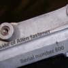
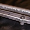
Pics of original jackshaft fasteners. There are two Allen head fasteners, that appear to be an Allen bolt that has been cut, drilled and tapped to fit over and engage a 5/16 NC stud from head. They are a length that goes down through the jackshaft carrier casting, and stops just short of the bottom. They cannot be removed or installed while the shaft is in place.

Attachments

Images (1)
  • jackshaft-3-text
This is the fastener that is missing in the picture that is 5 posts above.

quote:
Originally posted by JMM3:
Pics of original jackshaft fasteners. There are two Allen head fasteners, that appear to be an Allen bolt that has been cut, drilled and tapped to fit over and engage a 5/16 NC stud from head. They are a length that goes down through the jackshaft carrier casting, and stops just short of the bottom. They cannot be removed or installed while the shaft is in place.

Attachments

Images (1)
  • jackshaft-5-text
Jay,
Couple of things:
the 600 242 is the casting number of the part....just coinkydink that it matches your car!!! Smiler

Those Allen fasteners look like they would work well as you can still loosen them and get the whole mess off, with the shaft in place? Understood that they must be in place before shaft is installed....

My old steel bracket had just enough clearance in the bearing holes that I could tap the shaft in and out with a plastic mallet. That is the only saving thing that allowed me to change bearings out in the parking lot in Vegas one year! (Blew a front bearing....cheap or incorrect bearing seals I believe....new one looked much better! Better seals.)

If I can get conventional Allen headed bolts to work, I'll go that way... if not, then I like this idea too!

Spoke with another member last night at the meeting that is going to try some sort of double sided stud, to secure the intake manifold, and allow removal of the shaft and bracket without breaking the seal of the intake gaskets.....allowing water to enter the intake ports and the engine valley!

Certainly a unique and challenging feature of these cars!!!

Steve
Steve,

Every time I see more detail about how much brainpower is need to restore a Mangusta it makes me want to beak out the Sudoku games. I hope I'm ready for it when I finally do get around to starting.

John, those "bolts" were some late '70's hot rod guy's idea of cool. Pretty silly and they will certainly be going when I get on to the resto.

Mark
Mark,

Your puzzle point is well taken! Very much to the point in my progress or lack of lately!

Spent last weekend up in Gold Country near the small town of Plymouth. Attended a flea market where I picked up some tool widgit items, a wine festival with local wineries and restaurants doling out samples, and a small car show of perhaps 18 cars and trucks. Some really nice examples! My fav was a 1954-56 customized Merc. Sort of a seafoam metallic green with faded in highlights etc. Have pics to post later....

Before we left on Friday, I dropped by the neighborhood machinist's house and milled down a piece of aluminum that I will have welded onto the rear of the intake manifold, to act as the rear jackshaft support, as was on the original cast iron intake. It will serve to give the bracket some rotational strength. I also cut up a piece of black iron pipe (removed the threaded section) to form the basis of a tool for pushing or tapping bearings onto the shaft.

Monday night I spent hand filing and fitting this piece of aluminum to the back of the intake. Once I got that all squared away, I decided it was time to weld up the adjustable guide plates.... Tack welded them. Covered the valve springs and everything else with aluminum foil. It forms nicely around stuff and won't burn...and you can flatten it out and do it again! This went well! ...or so I thought....

Tuesday: During the day, visited the local "nut-n-bolt house" (Olanders) and picked up a set of 5/16"-18x3.5" socket head cap screws in stainless to use on the 4 bolts of the jackshaft. Pricey little buggers! Five of them ate up a $20 bill.... (need to get the socketed allen bit for these now too! 3/8" drive should be good.)

Also ordered a new set of valve covers from Rousch. They are Ford Motorsports covers, but Jack has the best price in town! $129 for a polished set! They will clear the rocker arm nuts with room to spare, and will have the old look of the Boss 302 covers. Finned on the top.... Would have loved to use my aluminum "Powered by Ford" covers, but they are just too low, and spacers cost almost as much as a new set of covers....so....it was really simple. M-6582-BOSSP is the part number.

Next....torque down the rocker arm studs and see where the adjustment is.....after the welding. Things start taking a turn for the not so good here.....

When mixing and matching parts, materials, and manufacturers, not to mention blazing a trail in engineering combo's of parts, Mr Murphy is bound to appear. He did. In oh so many ways....

When torquing down the rocker arm studs, I used a torque spec from an old Ford shop manual for removable studs..... Later I found out that I should have reduced that amount by a lot.... On one of the rocker studs, I believe the guy that machined my heads may have not taken out enough material and I believe I was bottoming the stud out....as it felt like I was moving aluminum instead of making things tight..... These instructions were later found in the rocker arm info!! Go figure..... I guess I should have "read all the instructions before beginning!"

You know you are in trouble when the torque wrench doesn't click...and it doesn't seem to get tighter.....and then your brain finally says STOP! (before you really screw it up!) Well, I think I screwed up....literally!

I gave up and started looking online for torque specs. I got nothing with the ARP studs. Their website does not distinguish torque specs between ferrous metals and aluminum......no help! Edelbrock says 50ft-lbs, but they cheat and use steel threaded inserts in their heads! (NICE!!!) After looking long and hard, a 40-50ft-lb figure appears to be in order. There is no mention of this in the Ford documentation because the heads were not designed for this type of rocker mounting! Gloom on me! (They DO mention the intake manifold torque specs....thank goodness for that! Although it really isn't all that different than the specs for the cast iron manifold!)

The studs I am using have a .710" portion to go down into the head. The top .125 of it is tapered and not threaded, to accommodate an 1/8" guide plate like I am using. When the heads were cut drilled and tapped, the machinist perhaps mistakenly countersunk the holes to allow for this upper tapered portion, not realizing that the guide plates covered this portion and that the holes could be made with very little countersink at the top! (I thought I took him in everything.... been too long, CRS...!)

With only about .575" of threaded stud going into a hole that is now shy another .125" of threads at the top of the hole, I'm getting very close to "engaged threads= 1x diameter" of fastener. Normally I think the spec is closer to 2X the diameter to get proper ratings......advertised for the fastener.....

Anyway, all of this turns out to be correctable and also a moot point. In the process of welding, the guide plates all shifted due to expansion/cooling...when I checked, all of them had splayed the rockers out off of the stems! (whatever is the opposite of pigeon toed...) I should have probably torqued the guide plates down first, then tack welded....

Thankfully I only tack welded them and was able to bust them loose again after a few seconds with a die grinder. Will need to set them all up again, and number the rocker arms to make certain there are no issues due to manufacturing variances, and then tack them again!

If this doesn't work, I will have to check out the tin Ford Motorsports version that I purchased initially, but rejected due to reports of them breaking..... If I go this route I will need to drill the holes deeper and tap them with a bottoming tap. Searched around the internet for a thread repair kit and taps....

The one thing I did do that wasn't messed up, was modify the drain boss to clear the motor mount bracket on the LH side of the engine block, as seen above in one of the shots on the top of page 10 I believe. Just needed to take a tiny amount of metal off for clearance. Smoothed it up and took off the sharp edges with a file. Add paint later.....

Wednesday: Ordered a heli-coil kit with .656" deep inserts. Should work fine for me. Will hopefully order the bottoming tap Thurs. and get that moving this way. No need to have this stuff immediately, as I am out of town working from Friday until next Tuesday when I go to work one day here, then go back down to LA for two more long days!!! No Goose time!

I also called the bearing house in Gilroy that I ordered my new jackshaft bearings from, to check on getting snap-rings for the new 52mm bearing, and found that they had them in stock! (.076" thick for an ID hole vs outside) I had stopped by my local Motion Industries on the way to work this morning, but they didn't have anything in stock and suggested that if I did order them, I'd be taking possession of a whole crap load of them!

I wasn't certain of the thickness of the snap rings when I was at work calling (didn't have a micrometer handy....) so will call Girardi back Thurs and get those moving this direction too!

Tonight I worked on getting the oil pan off of the old motor. I still had a long block out back in the shed, sitting on the bottom of an old shopping cart. It works well for a small block... My plan was to yank the heads which would allow my son and I to lift the remaining short block up onto an engine stand from where I could then remove the pan. Well, easier typed than done!

When I built this motor back in '01, I used head studs and the special spacers to adapt from 1/2" holes in the head, to 7/16" bolt size of the block. I loosened up the rocker arms, removed some for access to the head nuts, and took them all off.....but due to the studs, which sorta point all over the place, they don't just fall off like you would get once you pull all the bolts out.... All I can say, is that I didn't have any head gasket issues!!!! Eventually, with enough prying and grunting, and more prying and eventually loosening up the little spacers, I was able to get most of those spacers out....which then made it a micron easier to lift the heads up and off....but it took a LOT of prying and convincing....certainly not as sexy as when the guys do it on a top fuel motor!!!! Smiler

Eventually got both heads off (in the dark no less), short block up on a stand, fluids drained more final like, and the oil pan removed. Wiped down all the bores real good and generally cleaned it up a tad for storage, then bagged it and put it back in the shed!

Cleaned the oil pan up in my solvent tub and stood it up to dry. It appears to not have the provision for a LH dipstick mount...... Sorta rules that out......but I wasn't too wild about a LH version anyway.. It is a shame that this oil pan may now be too deep for the car!!! (Now that the chassis engine mounts are lowered back to stock!!!) Oh well, it's just money..... Maybe I can sell it to a GT40 guy!
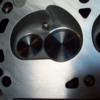
What I will do now, is design a drill guide that I can bolt down to one of the rocker holes to guide me when drilling the other side! If the heads were off, I'd be doing this differently.....but I have a $75 set of head gaskets in there that I truly do not want to waste! Just take my time, cover everything with masking tape and tin foil, and I'll win! I'll send this design off to my dad who can machine it up and mail it back to me in time to put it to use on Friday I hope!

I am also working on thinking up a set of pieces that I can use to push and pull the jackshaft in and out of the carrier bracket, as well as putting bearings on and pulling them off of the shaft.... I have some good ideas, but need to do some more machining and cutting of some 1/2" aluminum stock that I have! Not to mention visit Home Depot's metal section to see what I can find for suitable materials that won't weigh a lot yet will be strong under compression.....

OK, that pretty much sums up this week. Perhaps tomorrow I can post some pictures, as I won't be doing too much else, except for packing my bags to travel!

Ciao!
Steve
quote:
Originally posted by Mangusta:
... My plan was to yank the heads which would allow my son and I to lift the remaining short block up onto an engine stand from where I could then remove the pan. Well, easier typed than done!


Steve, Try this mount the engine stand fixture on the bell housing end of the block. Then tilt the engine forward and the engine stand the same. Tilt it back and Voila it can be done with much less effort, with a SBF maybe it could be a one man job Wink On my 429s that's the only way I can do it without the use of a cherry picker.

Denis
OK, back from the show, working on the car again and ran headlong into a small show stopper!

Jackshaft.

Reader's Digest version.... At the PCNC tech session on Sat, we tried installing shaft using center bearing, but the housing was getting pulled out of shape for some reason, not allowing proper alignment of the front bearing.

Removed center bearing from the picture and now going to run just the fore and aft bearings... Jack DeRyke has maintained that the Goose shouldn't need a center bearing.......

Got the shaft back in, brought it home and set it up on the new engine to check pulley alignment....UGH! IT'S OFF! (Why should I expect anything different? Smiler ) Problem is that it is off in that the pulley needs to be shortened OR the bearing placed further "in" or back on the shaft by about .200".

I know that the shaft is not the original, but as it would seem, is something that was made up to fit the Boss 302.....

I have no idea what I will find out back with the rear pulley yet.... Not that close to bolting it together.....

SO, what I am looking for, is a jackshaft to buy, borrow, or get dimensions from, IF any of you happen to have a spare, or an old one lying around! If I can cut mine to still fit, will do so. Otherwise may consider making a new one..... or buying a used one....if at all possible.

Let me know!
Steve
PS: There should be enough guys with disassembled cars that I should be able to find/borrow a shaft fairly easily, so no worries about taking a running car apart to make this happen!
Once I get going, I will make up a drawing for all to use in the future, like I did with the rear hatch engine covers.

OK,
Steve,

You can borrow mine or I can send you a drawing.

The jack shaft center bearing is an over constraint, as all three jack shaft bearings can not line up perfectly. When three bearings are all on the same center line, at least one of the three bearings will be misaligned (especially when supporting structures expand and distort on a hot engine). Just like a four legged table must bend for all four legs to touch the ground (three points determine a plane and a fourth point is an over constraint), the jack shaft bends in order to accommodate the misalignment of one of the three bearings. The force required to bend the shaft to get it through all three bearings is less than the capacity of the bearings, so it doesn't wear out the bearings prematurely, but three bearings in a line is not accepted engineering practice.

Having said that, there is a potential (and possibly important) benefit in using the center bearing. The center bearing dramatically raises the "critical speed" of the jack shaft relative to the critical speed with a two bearing configuration. The critical speed of the shaft is the rpm at which the shaft experiences the first mode of vibrational resonance (harmonic). It is possible that when using only two bearings, the critical speed of the jack shaft may be within, or close to, the operating range of the engine. By using a third bearing in the center, the critical speed of the shaft is raised beyond the engine speed range such that the engine can not possibly spin the jack shaft fast enough to get into vibrational resonance.

Since the jack shaft bearings don't wear out prematurely, it may be worth using the center bearing even though it is somewhat unorthodox engineering.

Dick Chandler

Rich,

If you have the time to put together a simple diagram, I would surely love to compare it to a couple of jackshafts up here that are still waiting to be installed! I missed an opportunity of another club member who installed his on Sunday! He was helping me on Saturday and hadn't known I was running into dimensional issues!! Ooops!

I'll put my pulleys back onto the shaft after I pull it all apart again, and see what the pulley center to center dimension is and go from there! It can't go back together the way it is.....

OK, just like Playboy wouldn't be the magazine that it is without pictures to go with the excellent stories, here are more pictures of what I have been rambling about!

Here is some catch up from two weeks back! ( A coupe of repeat pictures here.... oops!)

Pulling bearings from the shaft. Much discussion about whether these should be a slip fit or a press fit! Pulleys and nuts hold them in place..... OTC puller set purchased off of ebay, reasonable import stuff.


Here I'm pushing/pulling a bearing through the rear hole to burnish it a bit, and to make sure that they will go through! I pulled a bearing through each hole at least twice. Thin coat of anti-sieze was used.....that stuff gets on everything.....


I had to be careful not to put TOO much pressure on the bearings as the jackshaft bracket would distort! So when ever possible I pulled from the center hole to the rear or the front...not the entire span front to rear.

I have not cut any short rod for doing this....but it would come in very handy!!! Long rod= lots of nut spinning! You can see a long piece of steel that I had left over from making my extra rear shock support attaching points, to take up space fast!


Here is a close up of the rear surface after the bearing has gone through twice. Once you get it moving, it goes just fine. Not a slip fit!!!


Here is a problem area for me! Hex bolts just are not optimum for the two rear bolts in my setup. The fronts aren't a great fit either! Now my shaft has been remade....so I have NO idea if the diameter is proper or not.....your mileage may vary!!!!


Here's what I mean! I'm switching to allen headed socket bolts. Not ideal but better. I will need to get a "long shank" 1/4" drive bit...short ones won't cut it!


Here is my collection of misc bits and pieces that I had made up for pushing everything together. Note the pieces setting on top of the bracket, that I made from angle aluminum, to prevent the shaft bracket from bending under compression. They seemed to work....but it took a few sets of hands....tools are not finished yet.....to be one person things....


Closer view...
 

Large circular thing is for pulling rear bearing out. Circular thing in the middle is for pushing the rear bearing in, smaller circular thing is for pushing the front bearing in. Rectangular aluminum piece is for pushing on the circular things via the harmonic balancer puller. It needs a couple of holes drilled in it so that it will slip over the threaded rods when used for removing or installing... Pieces holding the jackshaft up are the drill blocks I had made up for dealing with my rocker arm stud holes. They worked great!!!

Front bearing installed. Note how it is just proud of the bracket! I think it needs to go in a tad....


Rear bearing in place, snap rings installed


Center bearing removed...
 

Here is are shots of the whole installer thing assembled.. It was good theory..... Would love to see what a good bearing shop uses!


Front pulley installed. Note the amount that the shaft sticks out! Pulley is also hitting the bearing seal, so would need a small spacer which would push the pulley out more...yet it needs to go in about .125" to align with the water pump pulley! So I think push the bearing in 1/4" (cut shaft to fit...) use a 1/8" spacer behind the pulley to keep it off of the bearing seal....and should be great! Will need to revisit this dimension, as there is a recess in the back side of the pulley that will need to be accounted for.....also!


Another view


Outward facing sides of the pulleys and the various pieces I used to space and secure. Rear is on the left and front is on the right.


Inward facing sides of pulleys:
 

OK, next pictures are not for faint of heart!!!! Drilling on a mostly assembled long block.....!

Drill block in place, drill stop in place on drill bit. Worked nicely!


A bottoming tap, for getting more threads into a blind hole.. Note how the tip is not so pointy, as most of that point has been removed to allow the tap to go in the hole that 2 or so turns! Use solvent, WD-40, or even water when tapping aluminum to keep the tap from gumming up.....


OK, enuf for me tonite! 16 holes are drilled and tapped.....on to push-rod guideplates again!

Steve

Attachments

Images (19)
  • blobid0
  • blobid1
  • blobid2
  • blobid3
  • blobid4
  • blobid5
  • blobid6
  • blobid7
  • blobid8
  • blobid9
  • blobid10
  • blobid11
  • blobid12
  • blobid13
  • blobid14
  • blobid15
  • blobid16
  • blobid17
  • blobid18
Last edited by mangusta
Mr Chandler, I couldn't agree with you more on the possible benefits of a center bearing for a rotating shaft.... but not a Mangusta jackshaft. First, the bearing spacing front to back is quite short so single-vee-belt driven deflections under power are unlikely, and as I remenber Steve's jackshaft, I think the material is tool steel and the diameter is (or was) massive overkill: large enough to transfer 500 horsepower- bigger than a ZF input shaft! I also suspect that heat expansion of the block & intake twist stock jackshafts and their aluminum supports far from an aligned center. But since my only shot at owning a 'Goose is now residing peacefully in a barn 6000 miles away, I can't check anything. Sniff....

Well, this has been interesting!

For a bit, I was thinking that my shaft had been remanufactured to some odd dimensions......very odd....

Rich Chandler has been an immense resource to me here, in that he not only sketched out a rough but very detailed drawing of the jackshaft from his car, but he also dug out the pulleys, bearings, and attaching hardware and sent pictures of it all up to me! Oh, and he measured up the front pulley for me too!!! More on this later.....

In an effort to get some small stuff done, since big stuff is just not happening right now.... I took care of this....

I am using a late model 5.0 roller block, which has a provision for an oil dipstick in the side of the block about 3/4 of the way down the LH pan rail, to the rear. I used a 1/4" NPT (National Pipe Thread) tap and gave it a few whirls into the metal, and filled the hole with a brass plug I found in my junk, coated with some Permatex #2B Form-a-gasket (non hardening sealer).


Since I was nearby, here is a shot of the drain hole boss that I had to take metal off of in order for the DeTomaso engine mount bracket would bolt up properly! Wasn't much, perhaps 1/8" of cast iron...


Next was the dipstick. Since I plugged the hole on the LH side of the block, (dipstick would run headlong into either the AC compressor or the coolant overflow tank...so opted for the stock location...

I am using a dipstick that came with the motor...found on many many many late model Mustangs, T-birds, Mark VII's etc. I cut the bottom section off of the tube first and filed down the sharp edges.


I then wiggled and forced it into the hole in my new timing cover....can't remember if this one came with a hole or I drilled it.....that's the problem with an engine build that spans years instead of weeks!!!!


Using a crescent type wrench, I reformed the little mounting bracket on the tube and was able to get the metal to line up with a convenient 5/16" hole in the front of the head. Drilled a suitable hole in this little tab, cut off the excess and filed it all smooth....

Using a tubing bender I have I managed to put a slightly different bend on the main tube...not much....and also I dimpled the hell out of the bottom of the tube, where the retaining guide wasn't fitting the tube real well.....oops! Can't see it when it is installed anyway......just little dimples....little bends!


Dipstick still moves in and out "ok" but it is dry and will be better once oil is involved!

Here is a shot from the business end...what you will see when looking in the engine bay....I hope!


I also installed the one unique main stud that I need for supporting the Aviaad oil pan pickup. I didn't have this piece when I installed the crank etc. Sorry, no pic's yet.... And I put the oil pan up under the engine hanging by two bolts. Will button that up once I am done making a mess out of the rest of things up top! It goes on once the top end is all sealed up!

OK, while chasing bolts or something or other, I happened to come across a little adapter that I knew I had seen...but couldn't find! Was driving me nuts!!! I knew I got this in a water pump that we bought for our 68 XR7.....I thought I threw it in my steel bucket of nuts and bolts, but alas, I found it one shelf up in my brass recycling bits!


THIS is the part that adapts the DeTomaso water pump pulley's larger diameter center hole to the water pump center shaft, to keep it centered!!! The four mounting bolts won't necessarily do this on their own, although you could get lucky like I had been doing......


Pulley on!

Attachments

Images (9)
  • blobid0
  • blobid1
  • blobid2
  • blobid3
  • blobid4
  • blobid5
  • blobid6
  • blobid7
  • blobid8
Last edited by mangusta

Back to my jackshaft pulley story!

I was just about to take the jackshaft apart again, and decided to check out some dimensions, since Rich has been so good to send them up! Turns out that they were all very very close! Over all length was just slightly different, but not too bad! So, I decided to play around with the pulley and see where I was... What I was up against was what you saw in the pictures a couple posts up, where the pulley stuck out too far unless I removed the spacers, which put the hub of the pulley into the seal of the bearing, as the pulley has a recess vs a protrusion.... It also has two holes drilled in it for set screws...told you this was an industrial pulley!!! If I cut the protrusion down to fit, I think it would cut into the set screw areas, so it either all comes off and I make a bigger spacer, OR, I do the RIGHT thing and get a pulley that is closer to the stock one!

Here are a couple shots of Rich's pulley!


Here's what I figure happened many moons ago...about 1974 or so... When the third owner installed the Boss 302, they raised the engine frame mounts to allow the headers to clear the frame rails! When they raised them 1.5" this raised the original 6" diameter pulley into the body just below the cabin rear window! SO, they grabbed their industrial A/C supply catalog and ordered up a 4.5" pulley and cut it to fit..... Where the original is now, is anybody's guess, but I will tell you it WAS in Fresno....back then. (Still have not found the third owner.....who did all this work!) I did find the 4th owner and the jackshaft bracket and an air cleaner, but he didn't offer up any pulleys....I guess I could call and check anyway, but I think all he got from the salesman was an extra unused piston....!

So tonite, instead of working on stuff, I surfed and learned all about grey cast iron, ductile cast iron, maximum distance per minute of pulley travel....and that the internet is full of all sorts of crap!

Grey iron will work well up to about 4000rpms, ductile iron up to 6500. I believe these are continuous operational numbers, and that they would flash higher....but not 100% on that.... Ductile iron has more nodular metal in it, like cranks and rods.... Blocks and stationary stuff is made from the grey iron which has more graphite in it.... Told you...!

So, I just may contact a pulley manufacturer and see what it would take to cut one out of some billet steel.......Give them the dimensions and let them roll..... not sure if my dad would take this one on!!! We'll see!!!

Here is one last shot for tonight. There was talk of "allen headed nuts" and such before, used in retaining the jackshaft bracket to the engine. Here is a shot of one of Rich's fasteners....appears to be made from a 12mm diam socket head cap screw, that was drilled and tapped for 5/16"-18 about 3/4" deep! It is meant to be used with a double sided stud, as was used on the intake's center 4 holes (Two on each side) in the stock config from Ford. He says that they do not fit tight into the bores of the holes in the bracket, so there is still room for the bracket to move around a bit. They do not act as locators...

I thought it was a pretty neat deal! Have some pic's from another crazy Goose owner that came up with a rather novel aproach at this whole deal too!!! Will post later....


Out!
Steve

Attachments

Images (4)
  • blobid0
  • blobid1
  • blobid2
  • blobid3
Last edited by mangusta
Bosswrench - After having read many hundreds of your posts to this and other forums, I am literally in awe of your automotive technical knowledge and wisdom. Your knowledge of DeTomaso technical issues is simply without peer. However, as to your opinion on the removal of the center jack shaft bearing I must respectfully disagree.

While the goose chase for a front pulley continues...progress today on more small stuff! Sheesh! So much small stuff!!!!

Called on new valve covers...that hadn't arrived while I was gone.... had been on back order from Ford, arrived at Rousch yesterday and shipped out today after the phone call to say "yes I still want the stinking valve covers!!" Smiler


Hit some shops and picked up more stuff...

HD vacuum hose and another 1/2" hose barb for the PCV line to connect to the rear of the intake.
 

This stuff is HEAVY walled and shouldn't collapse. I had been using standard heater hose and it was looking like it had collapsed or had potential to do so...... This piece will feed the brake system, so no goofing around here!

Stopped by my clutch guy and bounced some things off of him....namely clearance on the pilot bushing. Mine was looking a tad galled, but I believe I had the clearance set a little tight. Shaft is .5904"ish in diameter so went towards .5940" on the lathe. Was a little tricky setting up a used piece in the lathe...but with a little talent helping me out, it came out great!


It was either take a light cut on this, or machine a completely new oillite insert....

Also tried to get a new (BCA 1625?) throw-out bearing but both my clutch guy and the other place I picked up my hose at were out! Ordered one....

Also got some small copper washers for the clutch and brake fittings...."just in case!" Worst case they are spares....they don't take up much room in the tool box!

While I was out, my bearings arrived from Giardi Bearing, for the idler pulleys.

This is what I took out of the idlers (new bearings on the left):
 

The bearing I took out was a 6003 which is too narrow. To take up the space, the PM (previous mechanic) used snap rings to take up the slack! I had pulled the bearing out and replaced them with the same...and put the snap rings back in.... Since I have learned so much about bearings....I looked into a larger (wider) size and sure enough, a #63003 2RS1 was available! Ordered three so that I had a spare...just in case... "they're small!" Pricey little buggers!! Ran me just over $30 each! ...but they did deliver to my door!!!

Used my assortment of sockets and such to press the old ones out, cleaned out the dirt, lubed with anti-seize and pressed the new bearing back in place, reinstalled the snap ring...like new!!
 

Mounted both idlers back up to the mounts and confirmed proper line up. Had to work on the bolt for one side as it didn't move in and out of the bearing easy enough for my tastes, so just dressed it with a file and polished it up with some worn 320 wet/dry sand paper.

Back to the Sharks game! Tied up, overtime!
Ciao!
Steve

Attachments

Images (4)
  • blobid0
  • blobid1
  • blobid2
  • blobid3
Last edited by mangusta

Osofast,

I checked out those pulleys and at 5lbs for a 6" pulley, that is one lot of mass! I didn't see a V-belt on that page, but didn't get too far either....thanks for the idea though!

I've checked around a bit and it seems that machining something out of steel or T6061 aluminum wouldn't be all that difficult, just time consuming....

OK, back to the Goose chase!!!

Progress today in the spinterogino dept. (distributor!)

I needed to change the gear from a standard cast iron gear (marked with orange paint), good for regular flat tappet cams, to a steel gear (marked with NO paint!), compatible with roller cams.... I had previously pulled the gear off using my small press.

Getting the new gear installed wasn't going to be easy... (so what else is new??? Smiler

)

I tried this Sunday:
 

and this:
 

But it didn't work. Was still a press fit. Since dinner was ready... Smiler

.... I gave it a rest until I could get back at it today.

I had already guestimated and drilled one hole in my new gear at what I had thought was the proper location, based upon the hole in the gear I removed.. Recommended way to do it is to install new gear and drill a new hole thru gear and shaft and install roll pin... Well, who am I to do it the easy way....?

My guestimation proved off by .050" once I found the spec in the book!

So I pushed the gear off again using a tool that I got in an auction or such...somewhere, probably a Ford dealership...


Note that this is the recommended way to remove the gear. Note the little 1/4" stub (in this case one of those little sockets from a multi-bit driver set that I found somewhere....) sticking in the end of the distributor to press against. You can also use a piece of an old distributor drive shaft to either press against or hammer against, but you need to support the gear by the body of the gear and not by the teeth!

Here is the tool and gear:
 

The proper measurement for the distributor is .024" between the little (upper) collar and the body, seen to the left of the gear more "up" on the shaft... Mine was at .025" and I'm not going to redrill a hole for .001"...sorry!


However, the other measurement, from the distributor mounting flange (above the o-ring) to the bottom of the gear, is supposed to be 4.031-4.038" to align properly with the cam gear. I was off by .050" so that was not insignificant...

After polishing the shaft a bit, putting some oil on it, and pushing the gear on in a new spot, it went on nice and easy...but easy in terms of putting it on with a press! It took a few ups and downs....pushing it on...too far...pulling it back off a tad, until I settled on 4.035" or darned close to it!

I then drilled the hole in the gear using measurements and marks I had made and came out dead nuts where I wanted to be. Started with a 3/32" bit and once through one side of the gear, and knowing that the hole was lined up, I carefully used the 1/8" bit to drill the starting side, go thru the shaft, and then drill the other side of the gear. It worked for me, your mileage may vary!

Tapped the roll pin back in place! Bottom is done. Now to the topside!

This distributor was originally for a 1979ish Ford. During these years the 302's were very low compression pigs. As a result, the engineers could get away with running HUGE advance numbers. I found the tower in this one allowed 21 or 16 degrees. It was configured to the 21 degree location... When multiplied by 2 to get crank degrees, that comes out to a whopping 42 degrees of spark advance!

In discussions with the local Mustang shop who are familiar with this engine setup and compression ratio, they recommended 34-36 degrees total advance period, which is pretty much in line what I had been using previously with the Boss 302.

In my pile of parts, I found another DuraSpark tower that had slots of 13/18. I went with the 13, as 13x2=26, plus 8-10 degrees of initial timing would net me 34-36 degrees total advance. If I feel I could use more, I can simply advance the timing up to 12-16 degrees. Keep in mind that the DuraSpark II module has a retard feature during cranking that moves the timing curve back by 10 degrees to make starting easier! I like it!

Here is a shot of the new (old) tower installed and the one I took out is to the right.


The actual curve would need to be set up on a machine, but from the feel of the spring settings, this should be close! All in (full advance) by 2000-2500 rpm's! A quick check with the timing light will confirm or deny this...

I put all the pickup and stator parts back in the top of the distributor. Checked the pickup with an ohm-meter and found 600ohms. Spec is 400-800ohms for a good pickup module! Cool!


Backed the vacuume advance unit to "loose" but I do not plan on connecting it....at this time.

New rotor, cap adapter, and cap, and we are ready to roll! New wires are still in the box waiting.....
 

Putzed around with the new bottoming tap I received and finished up the one hole in the rocker arm mounts that I was installing a heli-coil in. This allowed the thread insert to wind further into the hole without drilling a super deep hole into the head.

Fitted one guide plate a little better to the stud and loosely installed the rest of the studs and guide plates.

Adjustment of rockers and guide plates is next, but not tonight!

Ciao!
Steve

Attachments

Images (8)
  • blobid0
  • blobid1
  • blobid2
  • blobid3
  • blobid4
  • blobid5
  • blobid6
  • blobid7
Last edited by mangusta
I checked out those pulleys and at 5lbs for a 6" pulley, that is one lot of mass! I didn't see a V-belt on that page, but didn't get too far either....thanks for the idea though!


A-B-C are belt widths and most automobile belts are A or B series V belts.
The numbers beside the letter i.e. A1, C3 equates to one belt A style belt sheave. and a three belt C style belt sheave.
Oh and Steve thanks for documenting the work on your goose, loved the multitasking on the grill!
Wink

Well, back from a great time in Reno! Passed lakes in the mountains still covered with ice!! Not so much ice on the way home though....5 days later!

One lone Mangusta showed up, so needless to say, I checked it out fairly well. Early car, #606, has a very unique "in-dash" AC unit as well as early round top side marker lamps. Was a conversion to an Edelbrock F4B many moons ago....as well as a set of Hall headers and cherry-bomb mufflers. Very sharp looking in red with black interior, took home the "most stock" award I believe. Only real noticeable deviation from stock is a set of aftermarket wheels. (Which the owner would love to replace with a set of stockers!)

Since returning home, not much progress on the Goose. Met with another local Goose owner, who lent me his jackshaft assy and pulleys to check out on my engine. His jackshaft bracket is an early version, with an extra mounting bolt in one of the center positions. If you look at the later ones, you will see a round area just behind the center bearing area where this was...

This version also had all three bearings held in place with snap rings, unlike the later version that I now have, where the front bearing is allowed to float.

I did pick up the new BCA1625 throw out bearing. Mine was new not that many miles ago...but since I'm in here, I'd rather spend the $30 and do it once! The old one can go in the tool box as a spare in case anyone needs one out on the road! I need to install it on the holder/carrier sleeve yet.

Have been a bit busy as I have detoured on a family car project.....getting the old family taxi running again. Blew a head gasket out of the blue....with only about 50-60K on it! (Replacement engine for the car...)

Here's a shot of what I've spent the last weekend and week nights doing!


Our son wants to head down to Monterey this fall to finish his business classes for college, but the idea of taking a pristine 68 XR7 Cougar down there isn't sitting well with him or the previous owner (me!)..... I remember driving a nice 62 Impala SS to college, only to return it home 3 months later due to numerous break-ins and attempts, getting hassled by the cops for out of state plates......not to mention driving it in the salt...!!!

So, the idea is to see if the new head gaskets hold up....and squeeze another 50-60K out of it! Should be ready for the scrapper after that!!! This is a late 97 4.6L SOHC engine that will go back into our 92 Touring Edition Crown Vic. Cleaned up all the surfaces, checked the #8 rod bearing for wear, found little to none, so it's getting 5 qts of fresh oil, a new filter for a few hundred miles, then another new filter and 1 qt of oil and it should be good to go!!! This picture was early last night, but later it had the front timing chain cover, oil pan, and valve covers on it. Tonight it got exhaust manifolds, intake manifold and most of the wiring. I don't have a metric 12mm harmonic balancer installer, so ordered up a special long bolt from Fastenal today and will turn it into an installer.....! But will need to finish that in the car as fully threaded bolts are not in stock anywhere around here! I believe it is coming from IL.... BUT, the important thing is that I can drop the motor in one of these evenings and then spend the weekend buttoning every thing up and plugging all of the wiring back in! Then one more project will be off my list, and back to the Goose!!!!!

OK, now for some GREAT news! While in Reno, I happened to ask Steve Wilkinson if he had any Mangusta front jackshaft pulleys.....he replied that he thought he had two of them! Called him up last Tues or Wed, and sure enough, he had two on the shelf! One had some brazing on the backside....and one looked like new... "I'll take the latter please...!"

Here is what showed up today!
 

It fits my shaft just fine, but I still need to deal with getting the bearings to fit a little better!!! A couple hours on a lathe and I should be good to go....make a few spacers and then start torquing down an intake manifold!!!

I think after that, it is carb and fuel line work to do, fab up some sort of throttle cable bracket, and then work on dropping the engine back into the car!!!!! WHOO HOOO!!!!

Steve

Attachments

Images (3)
  • blobid0
  • blobid1
  • blobid2
Last edited by mangusta
Steve, do us both a favor and double-pin the distributor gear on your 302. I'm hoping you didn't use a weak multi-layer spring-pin there. It's not just 351-C distributors that shear Ford's single roll pin, and you make the run into Nevada often enough that myself or Terry would have to go get you... Gooses do not flat-strap well.

Add Reply

Post
×
×
×
×
Link copied to your clipboard.
×