.....obviously early....as none of the Carello relays adjacent to the fuse panel are shown!
But that aside....it is somewhat functional at least in Italian as "a suggestion"!
Steve
It is good to see these De Tomaso books coming out.
Have you seen my book, BELLA MANGUSTA?
Dick Ruzzin
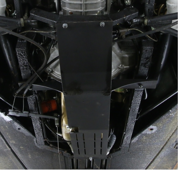
Steve, just to finish on skid plate...Our friend '696 (the gold car in Miami...really does seem to be a nice car) has a clear pic on skid plate mounting...I think I've seen others make this notch for the drain plug.
Nate, for me the hardest thing about the Schematic was dealing with the "2 halves" (where one page has a displaced gap with the other). Good news, the car is simple enough.
Dick, yeah, our family has 2 copies of Bella ![]()
Lee
Attachments
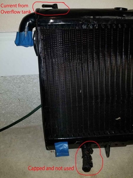
Am prepping for engine stand run of rebuilt motor and plan to use rebuilt radiator to test it. The picture shows a port at the top circled in red that was connected to the overflow tank in the engine bay since I've had the car
The bottom red circled port has been blocked off since I've had the car.
What is the correct connections for the coolant going into the radiator other than the main coolant input coming in from the thermostat housing? Should I be running the hose from the overflow tank to the top port (way the car has been for years) on the radiator, or the bottom port (blocked off for years) on the radiator?
Thanx
Mark
Attachments
I ran the top connection on my expansion tank to the small connection on the front "Y" Pipe off of the thermostat housing.
The lower expansion tank connection went up to my small connection on the radiator, where-ever it was..... I believe it was at the bottom....
My diagram I posted showed originally the lower connection on the expansion tank tied into the crazy hoses that were the heater shut-off valve circuits. I believe you said that you weren't running a heater???
For testing just connect the main large connections and don't worry about the small stuff. Connect it like it was in a regular Ford! Keep the radiator high enuf to be the "top tank" in a normal car, and just watch the water via the radiator cap there! Keep it simple!!!!
Make some noise!!!!!
Steve
Alright! Progress!!!!
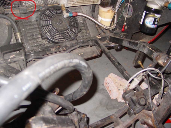
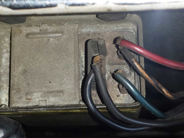
Re the relay above the AC condenser fan.....while the connectors from afar appear to perhaps be original style, I have no idea what it is for....unless it is for lights or the fan.
Follow the wires.
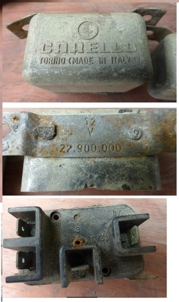
As for relays on factory wiring diag's, they are notably missing from copies that I have and what I have heard from others...... The two above/adjacent to the fuse panel are for AC, stuff under the dash..... and radiator fans if memory serves me. Carello....plastic housings....tend to "soften" with heat....!!! Keep some Bosch "relays on a tab" handy.... Don't forget to assure that your ground connector(s) to these relays are making good contact.....thru thick insulation!
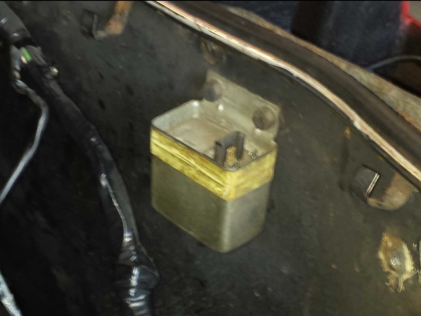
Ok, second relay....if this is on RH wall of engine compartment, I would bet that this is a voltage regulator of sorts.
Get numbers off of the cases of both....and you can likely find new replacements! The regulator came in two sizes....20A and 30A or 30-40.....and were paired with the Bosch alternator size....(current).....
These voltage reg's showed up on VW's and others...... IF that is what is is.
Mine was mounted wiring connectors down.....opposite of yours.......
Gobble gobble!!!!
Steve
Mark, the relay in the back isn't original; the voltage regulator (2nd [pic) was used on Mercedes and Porsche 914, check Bosch #30-051 or 0 190 601 006 (I have no idea if these are 20A or otherwise as Steve mentions). These are available as aftermarket, and probably won't take too long even to find NOS.
The fan relays Steve mentions were Carello, 22.900.000 . I haven't been able to find these anywhere...Lee
Attachments
If you burn up one of these Carello units, the BOSCH "block" relays work fine. Best is the ones with the mounting tab on them. They come in two flavors, 30 and 40amp. 30's should be sufficient for these cars, excepting some aftermarket fans!
Steve
Once I get car back from paint, I'll some sleuthing to figure what rear relay might be. Right now, am just building engine test stand wiring so that rear relay isn't a player.
Fan wise, I replaced my radiator fans with two 1500 cfm Zirgo's and used a couple of Bosch relays.
Mark
quote:Originally posted by LeeA:
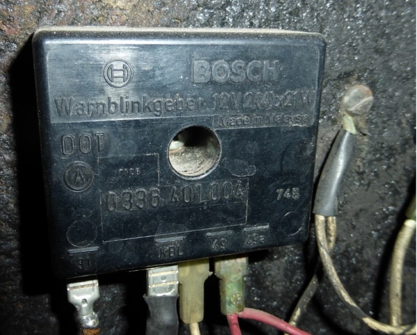
(Just adding a pic of the Bosch relay Steve mentions, must have been Hall that provided these ~30 years ago...!)--Lee
Thats a turn indicater relais ,this is not what Steve mentions.
Simon
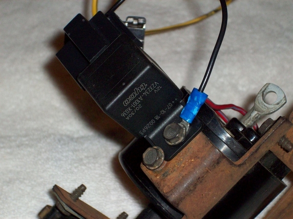
This is one of the cube relays..... in a completely different application....but you can see the mounting tab! There is a socket installed on this one.....which could be potentially used in the Goose, but not necessary.....unless all of your connectors are toast and need replacing anyway!
Attachments
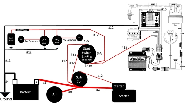
For you folks that are electrical gurus, how does this wiring set up look for a test stand to run Goose engine? The starter, starter solenoid, alternator, battery, oil press sensor, water temp sensor, and ignition system are the components I'll actually install in Goose so thought it would be good idea to test them. I had goose fans/relays/fuses wired in in my first incarnation of this but just decided to put a floor fan in front of radiator when temp gets to 180.
Attachments
I keep a set of manual gauges for oil and water monitoring..... hook up the coil with a paper clip to power....not really.....but a big wire.....jumper cables to the starter solenoid, some gas in a can and hit it!!!! Make some noise!!!
Drawing looks good with only one question about #12 wire to 1-B on ign switch for alt charge. I would think this connection would be to #2 for the "run" or "ign" mode? Not sure what the #1 terminal is here......
As for the Accel stuff and tach......hafta go with what they recommend in their papers.....
Video at 6????
Steve
Thanx much.
There is no real stock mirror on a Goose....many were shipped here without...and dealers popped whatever they had on a fender or door and away it went......
You might post a pic of the mirror you are dealing with...perhaps then help can be offered....
Glad to see progress!!! I bet you are also!
Steve
4263598 -
https://www.ebay.com/itm/RELE-...p2060353.m1438.l2649
I bought "Itab" made relays, which (like the Carello) are also marked "Torino" and I'd bet were a common manufacturer as the Carello. I did buy a NOS Carello 22.900.000 many months ago, it was very expensive but I was drunk with the find...
The Sipea part numbers for this relay (with metal instead of plastic body) seem to be 5170 and 7810.
Good find!!! I would venture that your theory of manufacturer supplying others is probably not far from truth..... That looks too similar!
I found some Carello relays on some Italian car in the junk yard years back, but found that one was a "NO"= contacts "normally open" and one was "NC"= contacts "normally closed".
Some relays, like the small cube Bosch types may have both options are are great substitutes in a jamb or as spares.... But the Carellos seem to be one or the other!
So, buyers beware!!!!
I like the circuit on the plastic to "explain" how to hook it up!!!
Cheers!
Steve
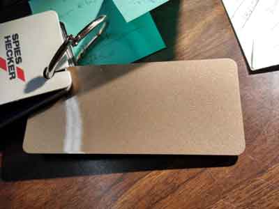
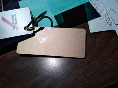
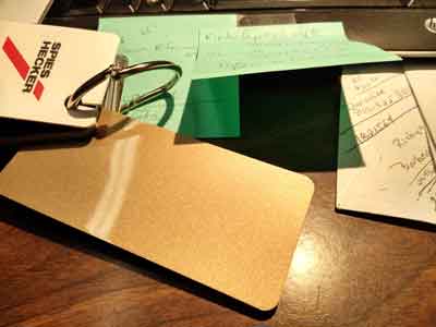
Well, a little movement in the right direction. Almost 4 years since going to paint shop. Car has been red, but original color was copper. New color will be as close as I could get to metallic platinum on the prototype. Attached are samples of the paint selected. Since the prototype's metallic platinum was not one of the original gooses colors, this Porsche color appeared to come the closest.
Attachments
Keep up the good work! A few months ago there was a very original/low mile goose for sale, I believe it was out of Florida. I thought it was the same color as the original prototype, but that was just an assumption. It looked pretty close to your sample chips. Sadly can't locate the ad at the moment.
You know, I remember seeing that car advertised now that you mention it and show the pics. I am guessing that is the color my car was initially (copper). I am really hoping this new color is close to the prototype if not exactly the prototypes color.
Found this on youtube this morning:
https://www.youtube.com/watch?v=5p4JLdDe8SY
The car in this youtube video looks like the folks who restored this car in the 90's were trying to match prototype color as well. This is pretty close to what I'm hoping for.
Goose should be coming back from long paint (in shop since 2015 in the next couple months - I hope!!).
I know I need to rebuild front suspension and steering (as well as rebuilding the rest of the car) . Couldn't find detailed writeups on these items. Anyone have this data?
Thanx
Mark
Others can likely provide better info but here are some off the cuff thoughts;
Inspect front A-Arms for cracks or signs of stress. If they are painted or coated, it may be worth stripping them to reveal the metal. Rear A-arms are known to fail as well.
Make use of the grease fittings to lube up the joints.
Replace shock and spring which can be sourced from PI motorsports. For mine there was some light machining work needed to attach them properly, but nothing major.
Find an alignment shop who is familiar with old Italian cars. Bump steer.
Bushings may be in poor condition. Consider cutting new from Delrin. Actually not certain if Delrin is best for this application but I have found success with it as a bushing material on other cars.
Since it's all apart, you might as well address the rear transmission support. There's a great amount of detail related to that topic on these forums. I won't try to re-hash it here except to say it's important if you'd like the car to handle reasonably.
I know little to nothing about the steering. It sure would be nice if there were a rack with a faster ratio which could be swapped for the slooowww factory rack. One day when the car is more sorted out I'd like to attempt adding an electric power steering 'helper'. They are popular in the offroad world.
Mark, Scifi,
Some observations of mine over the years spent getting our car back on the road....and some efforts of others!
Front A-arms: Your early car likely has "rev-A" lower arms. These have metal strip welded along bottom of tube(s) but stops short of the ball joint cup. This is where they are known for failure...cup busts right off. Rev-B arms used a metal "U" channel about 3/8" or 10mm square which is welded along the bottom at intervals, and extends over the BJ cup area strengthening the whole mess. I had one of each on my car due to accident...welder could only find solid bar to use, but I think "U" style is available if ya look...... (MSC ???)
Front Lower Bushings: Inspect and fab replacements as needed. I put some new ones in.....but they didn't offer much improvement if any, over the old ones! They do need some lube all over everything to prevent squeaks....there are no grease zerks here.....luckily you can just lift the corner of the car to unload the suspension and the two bolts can be removed allowing the lower arm to be dropped for servicing.....doesn't affect any alignment.
Ball Joints: Inspect for blown apart ball joints. Originals appear to be two pieces of stamped steel welded at the edges. You can expect multiple pieces to fall out if you still have originals. New ones are cast units- Fiat 124 uppers if memory serves me. DO NOT grind the a-arm cups to accept new ones...... get the proper ball joints...! They are out there and readily available.
Rear A-arms are a little more beefy- I had no issues with these.... Often bent from idiots raising car with jacks under arms......!
Trans support: Lots said about this, but only one modification I would accept on these cars, which is to add inboard connections for the ladder bar at the top of the shock towers. (Inboard about 5-4" from outer upper shock bolts.) This will "help" prevent catastrophic failure if the shock tower cracks! Don't ask how I know this...... Easy enuf to do.
The bushings at the outer ends of the trans cross member are the same as the stock shock absorber bushings....if you have any good left in them.....but these bushings usually stand up better in the crossmember position! Not sure of availability any longer....you may need to fab something up!
I added a small stiffener bar between the outer mounts of the trans crossmember to prevent "some" amount of frame flex.... I know that other solutions have been suggested for preventing "Z" flexing of the chassis under hard cornering...it's real.....but quite frankly, it's way easier just not to "hard corner".....! After all, you are driving a 401K plan that has performed handsomely over time....no need to trash it senselessly now! IMHO, if you NEED to go hard cornering, buy a different DeTomaso or a late model 5L car and have at it..... Drive your GOose in a gentile and stately manner around curves! ![]() )) You will look fantastic doing it!!!!
)) You will look fantastic doing it!!!!
Steering rack: While the RHD cars allegedly had a swap rack to drop the ratio, I have not heard of any for the LHD Goose. In my experience, after now driving a Pantera for a while, the Goose rack feels very comfortable compared to the lower ratio in the Pantera. Not ideal for close corner fast-slow speed maneuvering, but since you are carving the corners off of your new tires, and stressing all of your frame member attachments, just don't do it. Your car looks fast sitting still....... The higher ratio rack makes the car easier to control in and out of parking spots!
Bump Steer: Ugh. We have one or two members here with extensive frame/steering knowledge that set out on an effort to cure this issue. The results were either epic failure, or "it fixed some of it". The latter required machining of the outer steering rod on the spindle, spacers for the tie rod ends.....and perhaps a little more. More than most would like to undertake....perhaps. Attempts to raise or lower the rack find interference from the frame in every direction! Wholesale redesign of the front frame members required. Not going there!
I would think that when doing close to triple digits on a bumpy road is where bumpsteer would be an issue...and not on smooth roads. So, stay off of bumpy roads when driving fast! Your chassis will love you for it!! ![]() ))
))
Love the car for it's beauty....forgive it for the defects, and "drive around" the bumps!!
Cheers!
Steve
Thanx Steve and SCIFI
Here were the front end 'symptoms' before I took it into paint...wheels splayed out to some extent when steering wheel in normal position, and lots of play in steering wheel...I could move it back and forth from 10 to 2 and the wheels wouldn't move...almost all the rubber boots in the front end need to be replaced (and I'm sure the bushings are right there with them). Any ideas on what the major problems might be?
Since the chassis has everything removed for the paint job, when I get it back is the time to completely take the suspension and steering apart and rebuild to something acceptable to 'drive like a 401k' (I like that Steve). I'll look for all the items the two of you mentioned. Any gotchas on taking the front end apart?
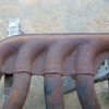
Also Steve, have my 69 Boss 302 motor rebuilt ready to test run and reinstall into the chassis/frame that had been modified back in 1969 (professional job vs hack job) to accomodate the wider heads and sit low in the engine bay to fit comparable to a 289/302. The OEM drv side exhaust manifold is fine and fits perfectly in the modified frame. The OEM pass side exhaust manifold is a franken-manifold since the exit from the manifold had to be relocated low and between the two middle exhaust ports. My options are: take the franken-manifold and have it refreshed to patch cracks on old welds and redo bolt holes, or try to build a set of headers (options being weaving thru frame low or going high like Dick Ruzzin did in his car). What are your thoughts?
Mark
Mark,
Re the "lots of movement" in the steering wheel..... check condition of ragjoint, the tiny (unobtanium unless in Europe) U-joints, and after that, my guess is that it is all in the rack gears. Rack is simple deal.....only two moving parts! Clean and inspect rack and input gear for wear/play.
Front end is pretty easy to take apart. Upper shock bolts can be fun... Upper a-arm bolts could give you pain if they are corroded in place. Clean and grease before assembly..... Nothing really major....not much to it all. If you unload both sides at once, sway bar connections will come apart more easily. Be careful not to damage threads on outer tie rod ends when taking it apart. Use two hammer method to "compress" the steering arm end, to pop the end joint out of the arm. The parts on the steering rack ends to the tie-rods are specially modified parts in some cases. Not "off the shelf"! (This may not apply to late cars)
Boss 302: ......after fighting with the crummy fitment of the headers with my Boss, the raised motor mounts, air cleaners that wouldn't fit, and more..... namely being the 331 5.0L based SBF engine that I put in place(!).... that engine ran SO much better than the Boss......BUT, the Boss had issues due to mod's meant to "de-perform" it to make it more driveable.....which didn't quite work..... It should have ran and performed better!
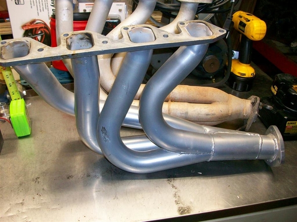
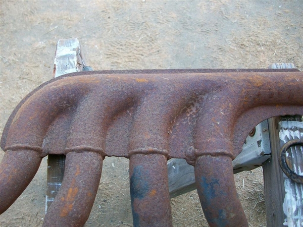
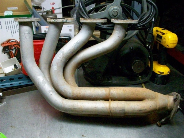
As for your "franken-manifold".....tough call! I would have offered you my "franken-headers" from my car, BUT, they were 2V port sized...not the 4V that you have! Is there ANY chance that a 70-73 351-4V right hand manifold might be more easily modified and substituted for your chopped up Boss manifold??? If not, I think I might be inclined to go for a new header....with the ugly being the fact that you're not going to find anything out of the box to fit! Although, that said, you could have some luck perhaps, with a set of Pantera headers to start with! I think I have a couple of sets of original exhaust headers with slightly eroded end flange areas (at muffler end) but the top section may serve as something to start with???? May be easier than a flange and a "box-o-curves" kit that you would likely need!
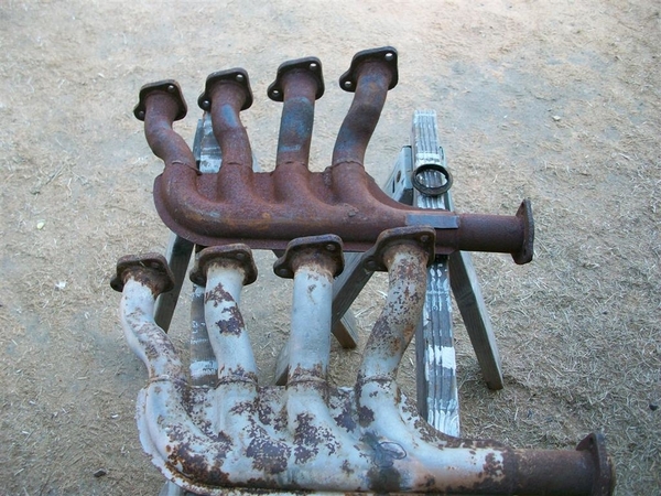
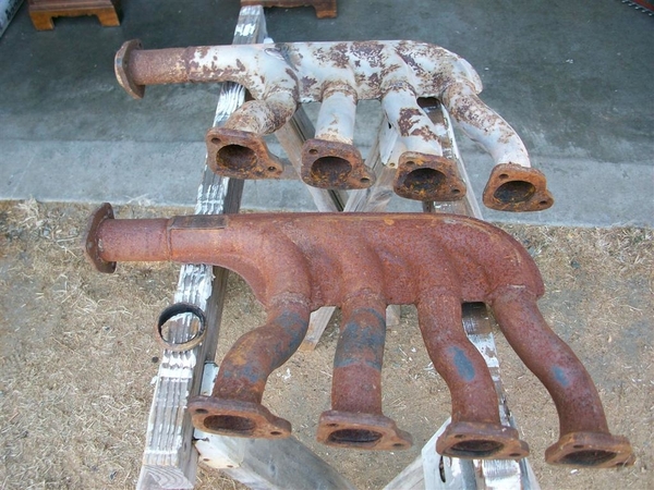
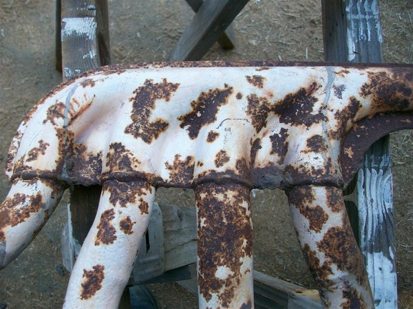
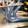
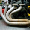
Here are some Pantera headers that I have, some have cracks in all the normal places.....! So good candidates for mod or copy.
Gotta go play plumber...ugh.....!


