@rocky posted:

Can someone help us keep the players straight?

Muttsjet - 8MA0642  Car Done?

Lee - 8MA???? Car Done?

Mike - 8MA???? Car Done?

Maugusta - 8MA????  Car Done & Sold?


Thanks…. Hard to keep straight, but I know this thread is for you, and not me…

Rocky

8MA-596

Switching from injection to Weber's. Easy right? Well, life got in the way and I probably can't touch the car for the next 6 months. When I do get back to it, probably have 3 months of work to do. Otherwise the car is in decent shape.

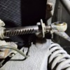
Ready to reassemble drivers suspension and steering. Can someone confirm best grease to use for steering and how much to put inside gaiter? What is the grease gun attachment called to put grease in heim fitting or should I just get the small grease gun for filling heims mentioned in another thread? Confirm RERS 5 is the correct rubber covering for the front steering heims?

Attachments

Images (1)
  • steering

   If you cannot get the original Italian stuff, the owners manual calls out precisely the use of "MOBILEGREASE SPECIAL" for the front bearings and steering rack...Another fine substitute is whatever you have (!).

  So whatever cool stuff PepBoys is selling for wheel bearings, just make sure the heim is cleaned of all old tarnish and then spend some Spa time working the new grease around the joint. I think there is really no point in overpacking inside the boot, work enough to cover the bearing and avoid a grease aquarium.

   Getting the boots over the heims is super simple. Finish by inserting the alignment spaces and voila, good for another 50 years.

Last edited by leea
@leea posted:

      Getting the boots over the heims is super simple. Finish by inserting the alignment spaces and voila, good for another 50 years.

I used a heat gun on the Heim boots to soften them up...  Didn't take long...  The boots went from a matt finish to shiny when heated, then slipped right on...   

I agree with Lee that choice of grease inside the rack may not be that critical...  The steering shaft isn't exactly spinning at high rpm and heat build up is probably not a concern...  Just keep it lubed with SOMETHING and you should be fine...  (In my opinion ~ FWIW)

MH

I think on page 18 of the owners manual, it says to replace the grease when the rubber boot crystallizes to plastic and then breaks open....see even older comments on this from smart guys who wondered why DeT used just half a boot (!) But yeah, its hardly as if there is going to be a lot of rotation inside the heim.

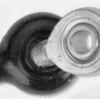
The best picture I can give on installation of the boot is attached, the sequence is;

- put the Heim threads thru the small hole.

-take the rod you'll attach it to, scrunch the rubber up enough to catch the thread.

- make a big pull. Rubber is magic.

Attachments

Images (1)
  • birthing heims
Last edited by leea

Back to work after some elderly parental issues...

So, steering rack heim off and regreased with grease gun. Have heim boots and special pliers to get heim boot on.

Am curious, since my jam nut is welded to the large circular metal disc, and I had to remove this jam nut combo from the heim joint to get the jam nut combo into the end of the boot (heim would not fit thru small opening on boot end), is it hit and miss to get it all reinstalled to same location?

I did take some measurements before I disassembled the heim to jam nut/metal disc combo: given the placement of the jam nut combo on the heim joint thread, it took exactly 18 full turns of the heim/jam nut combo to get it off...the distance between the outer edge of the jam nut and bottom of inside edge of the heim body was 16mm...the distance between the inside edge of the jam nut and outside edge of the heim body was 56mm.

....as for the wheel bearings....

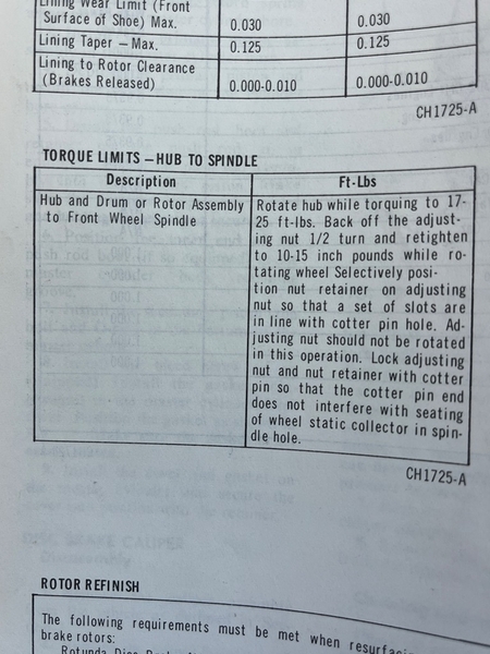
The Ferrari procedure speaks some truth, but final torque is WAY wrong...   Since you are using "Mustang/Ford" wheel bearings..... I'd go with that procedure in the Ford books as well!

Pantera procedure is close to what you want to do......butt IMHO way too much subjective feel....and GOING AMISS!

Mutt....... you should really go in and just delete those references in your post. Wouldn't want to mislead anyone....Ferrari or otherwise!

BELOW EDITED 8/14/2024 1PM PST

The initial torque tighten 17-25FTLBS WHILE SPINNING THE ROTOR to seat the bearings.  Loosen 1/2 turn retighten 10-15 INCH LBS while again spinning...  This amounts to pretty much "thumb tight!"  Use that new HF inch lb torque wrench rotting in the bottom of your tool box drawer!!!

These are tapered bearings, so they can handle a little preload.  12FT LBs IS TOO HEAVY!!!  Would likely burn up the bearings in short order!!!!  Don't need that!!!

Wrench on!!!!
Steve

Picture attached from 1970 Ford Shop Manual- Mustangs Cougars etc.wheelbrngtorq1
Attachments

Images (1)
  • wheelbrngtorq1
Last edited by mangusta

.......I wouldn't go any higher than that in aluminum for a smallish bolt..... secure with at least blue loc-tite.....red if you expect to challenge the braking system on an hourly basis!        Don't want to break 'em or strip 'em!

Fun working on a car with absolutely NO technical references 'eh???    Pantera not even something you can refer to either!

If you can find one of those "torque" charts showing recommended amounts of tight for various sized of bolts, that can come in very handy, but looks like you may have that already!

Some of the factory Ford shop manuals had a section or page with that on it....just trying to think where else.....  Fastenal website could have it....MSC.....  Google if nothing else for a chart.

Gettin' there!!!!
Steve

So, which would be better for bolting hub to rotor given I cannot find M8-1.25x28 partially threaded bolts in 10.9 or 12.9 grade

a) 4 bolts 'like the old bolts' that appear to be grade 8.8, M8-1.25x28, are partially threaded to 'match no threads  in hub' (about 8mm), threaded to match the threads in rotor (about 20mm), and will take about 18ft lb of torque

or

b) 4 bolts that are grade 10.9 (or 12.9) , M8-1.25x28, are fully threaded bolts that 'don't match no threads  in hub' (about 8mm), matches threads in rotor (about 20mm), and will take about 27 ft lb (or 31 ft lb) of torque.

Question is which makes for  strong hub rotor assembly, matching the partially threaded old bolts that align with the bolt hole threading, or going with the 10.9 (or 12.9) stronger bolts that won't have bolt hole threading thru the 8mm of the hub?

Dang!   I do not recall what I used for pads in the Goose!!!   I know I put the EBC "street" pads in the Pantera and they perform nicely, so if that is what you have here....you'll like them.   You do not want anything metallic that you need to heat up before you can stop! 

These would be same as a "street 427 Cobra" in the EBC catalog I believe.

Cheers!
Steve

@mangusta posted:

Dang!   I do not recall what I used for pads in the Goose!!!   I know I put the EBC "street" pads in the Pantera and they perform nicely, so if that is what you have here....you'll like them.   You do not want anything metallic that you need to heat up before you can stop! 

These would be same as a "street 427 Cobra" in the EBC catalog I believe.

Cheers!
Steve

And they Grind down your brake discs, almost the same amount as the brake pads… very costly proposition….

Checked parts manual, but unlike most cars, there was no washer between outside bearing on hub nut. Confirm this is correct? I assume next step is to take a chisel and pound the top edge of nut into the two indentations in the spindle. Correct?

Dialin indicator indicated about 2 thousands of movement after tightening nut and adjusting it a couple times.

Attachments

Images (1)
  • hub nut

Now have pass front end (brake, ball joints, tierod) pulled apart for refurb and new parts, and am comparing it to my completed drv side.

If I wanted to start from scratch on front wheel alignment, is their an initial factory number of turns (my drv side was 18 turns) for the heim connected to the rack? Additionally, my drvs side tie rod was 57mm from outside edge of tightening nut to center of tierod joint (the pass side is 69mm). What is an initial setup parameter for the tierods?

Once rebuild complete, I'll perform a manual home alignment and then take car to the shop for an accurate alignment.

Pass side suspension rebuilt. Just need grease pass bearings and reinstall brakes on both sides.

Take a look at these pics. Confirm original jack point still useable on side of car (appears to be). Confirm the black frame components abeam the red heads of each jack stand are good for supporting the car. You can see from one pic that pass rear wheel exploded when I put to much air in, and rear now supported on wood block under suspension (which is luckily as I had put these blocks there just in case tires failed (they are old!)).

Attachments

Images (3)
  • 1000007380
  • 1000007381
  • 1000007382

Front end done: brakes rebuilt (new pistons/seals, cleaned out front brake lines) , wheels (repacked new inside/outside bearings, outer races, and lt/rt nuts), steering (new boots and grease, greased heims and new boots, new tie rods), and suspension (new ball joints). New EBC DP2223 greenstuff pads arriving this week.

Starting back end tomorrow. Unless I can tell bearings are an issue (ie, looks like press required for bearings  from reading forum), will probably just rebuild brakes, clean out lines, and try to grease as many heims  as I can.

Finally back at it. Moving to rear suspension/brakes/bearings. Heim joint suspension wise:

- Anything besides getting grease into all plethora of heim joints thruout the rear if car tracked well before rebuild?

- Brakes and ebrakes should be straight forward rebuild as were the fronts.

- Rear bearings...if I get brakes/ebrakes off, and dragging stops when I turn disc, will probably skip new rear bearings (read thru https://pantera.infopop.cc/top...-bearing-replacement and https://pantera.infopop.cc/top...539#1598208420767539 and looks pretty painful to get at bearings to replace unless absolutely necessary)...if I go for it, looks like  inside nut comes off and disc/spindle/hub assembly pulls out without needing to take anything apart (learned my lesson from the front). The question then will be the two articles above and getting bearings out and back in.

Different topic, I think the paint shop lost and then made rudimentary fabrications of my front hood latches (part # 11 page 10 of the parts manual). A picture of what this part is supposed to look like would be greatly appreciated.

-

Attachments

Images (2)
  • 20241019_145958
  • 20241019_150046

Add Reply

Post
×
×
×
×
Link copied to your clipboard.
×