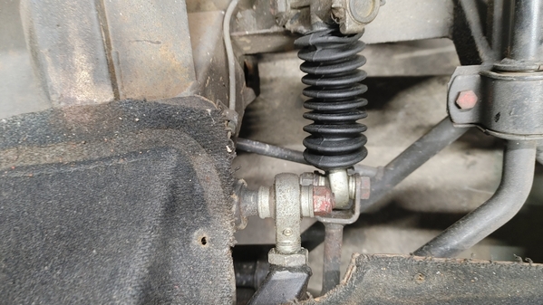
Looking for thoughts on distributor swap.  I'm considering purchasing this as it appears to be a direct swap without an external box so I can keep the stock look.  It will give me an electronic ignition and rev limiter...  (I hate points)

https://www.summitracing.com/p...x-d7130800/make/ford

Anyone see any issues or concerns?  I will be using the stock Mangusta air cleaner, so clearance it always a concern.

MH

If you must....... simply put a Pertronix unit in your existing distributor.  Valve springs will be your rev limiter............if your eyeballs can't read the tach!  Which being Italian, is only a suggestion....!  Perhaps they now have a drop in unit that has the rev limiter feature, negating the need for a new dist' body?

I am more of a fan of Duraspark II for run of the mill "sane" driving.    No one should be taking their GOose to the rev limiter anyway.....as it takes $1K off of your 401K each time you do that.... !        Easy start on high compression engines, works, works, works......   Lube the center shaft of the distributor every oil change and you should be golden for the rest of it's life!

Cheers!
Steve

@mangusta posted:

If you must....... simply put a Pertronix unit in your existing distributor.  Valve springs will be your rev limiter............if your eyeballs can't read the tach!  Which being Italian, is only a suggestion....!  Perhaps they now have a drop in unit that has the rev limiter feature, negating the need for a new dist' body?

I am more of a fan of Duraspark II for run of the mill "sane" driving.    No one should be taking their GOose to the rev limiter anyway.....as it takes $1K off of your 401K each time you do that.... !        Easy start on high compression engines, works, works, works......   Lube the center shaft of the distributor every oil change and you should be golden for the rest of it's life!

Cheers!
Steve

Does the Dura Spark fit under the air cleaner?  Any issues with wiring to consider?

MH

I think you're referring to the "big cap" vs the normal cap.....  IIRC it is very close with the original air cleaner.  I used the large cap on mine, however, I had to make my own air cleaner for other reasons (taller intake!).     The DuraSpark II system will work with the small diameter cap just fine.  The large cap came about to control spark "scatter", where spark could jump to the wrong terminal under some conditions.

Wiring consists of using an original or prefab harness from control box to distributor, two wires to provide "ON & START" to the control box, and then reuse the original coil to ignition switch wire.   I think I wired in a relay to provide the either the start or run signal for some reason to do with the original Goose wiring at the starter solenoid.....  Would need to dig out my notes to confirm this.

But it was a fairly easy job to do.   I found an original dist-control box harness from a late 70's early 80's Galaxie-ish car, extended it to fit where I put the control box, and wired in the two power wires (start & run) to the control unit, and also into the original coil wire as needed.

I put my box back on the rear engine panel below the air cleaner  duct hole but it could go anywhere away from major heat sources.

The 10 degree "retard at start" provision of the 'BLUE' strain relief control box allowed me to run a "mechanical advance only" distributor of 8 degrees, and a total all in timing of about 34 degrees. At start the mechanical advance wouldn't yet be active, so now the advance is only 26, bring in the 10 degree retard and my initial timing needed to be 16 at the harmonic balancer....doable!  My compression ratio was somewhere in the 9.5-10.3 area (CRS!) running alloy heads, and it cranked over just fine in all conditions I ran into driving it to POCA rallies in Vegas and Phoenix!

I could have run a vacuum advance distributor also, but would have just limited the amount of vacuum advance......to get a tad more fuel mileage out of the deal. But I was getting close to 20mpg (again IIRC!) on regular pump garbage gas!!!

Your mileage may vary!!!
Steve

@rene4406 posted:

Excuse me for going far back and talking again about the Rub'n buff for the gearbox. Looks amazing and I'd like to apply some to my Pantera gearbox but I'm wondering what temperature this wax can withstand and how resistant it is to oil or gas drips???? ?

I haven't put it into service yet, but i know of several people using it on vintage Mercedes aluminum valve covers for years and they all love it.

One note, the commonly used color is "Silver Leaf", but personally I find "Pewter" to look more correct as the silver leaf seems to me to be unnaturally bright.  The pewter color looks more like the natural aluminum to my eyes.   If your order it, a little bit goes a LONG way and you can order multiples of just one color or multi color packs.  The tubes are small, but just one tube will likely do the entire transaxle AND the bellhousing!!!  I also recommend using a combination of cloth, Q-tips & stiff tooth brushes for application, and of course, thoroughly clean the piece before application

and WEAR GLOVES or you'll be silver from fingertips to elbows in no time.

Let us know how it turns out for you.

MH

Last edited by mkeh

I am still attempting to find a suitable replacement for the bitumen impregnated fiber board firewall pads. I have found the Filzfelt ($$$) but it is just the felt, not bitumen impregnated. I know we've discussed this before, has anyone found a replacement they liked? or something to avoid?  I got some that vintage Mercedes use and while it looks great, it's much thinner.

I am missing the two sidewall pieces, if anyone has measurements and/or pics of original pieces in those locations I would appreciate the info.   Same with the asbestos panels, I have the frames, but haven't located a decent replacement for the asbestos...

MH

Last edited by mkeh
@mkeh posted:

I haven't put it into service yet, but i know of several people using it on vintage Mercedes aluminum valve covers for years and they all love it.

One note, the commonly used color is "Silver Leaf", but personally I find "Pewter" to look more correct as the silver leaf seems to me to be unnaturally bright.  The pewter color looks more like the natural aluminum to my eyes.   If your order it, a little bit goes a LONG way and you can order multiples of just one color or multi color packs.  The tubes are small, but just one tube will likely do the entire transaxle AND the bellhousing!!!  I also recommend using a combination of cloth, Q-tips & stiff tooth brushes for application, and of course, thoroughly clean the piece before application

and WEAR GLOVES or you'll be silver from fingertips to elbows in no time.

Let us know how it turns out for you.

MH

Thank you for the answer.

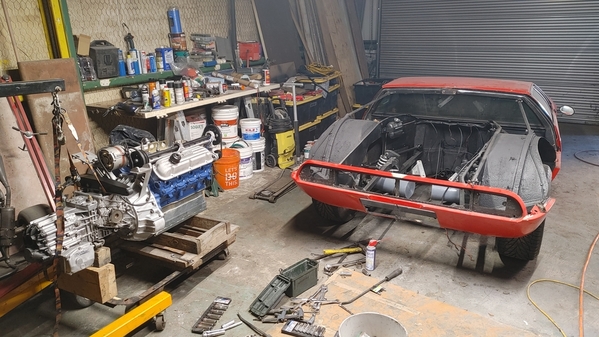
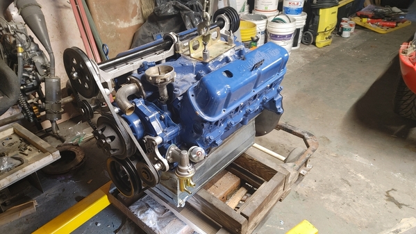
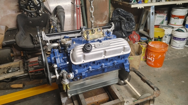
Sorry I haven't posted updates on awhile, but refreshed engine has been sitting on a pallet ready to go back in... 

So far aside from the ol' take apart, clean and paint, I've put in new rear wheel bearings, new hard lines for brakes, refurbed ebrake cable, new bushings in frame bridge & sway bar, new pistons in calipers, new brake pads, new firewall pads cleaned and finished ZF, new pilot bearing, new clutch disc, new heat shielding (replaced asbestos), new throw out bearing, new brakes hoses...  and probably a few dozen other bits...

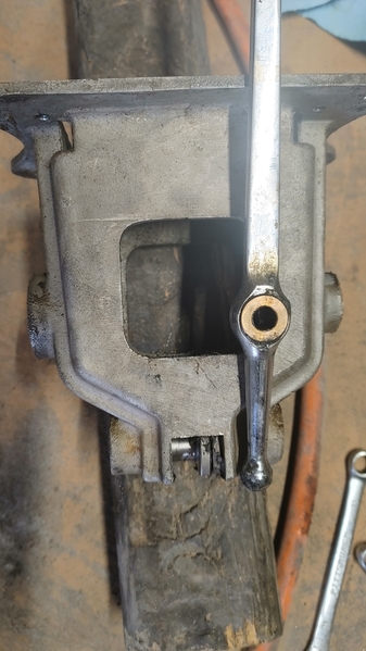
Today's WTF is putting the shifter back together...  The shifter itself doesn't go all the way in...  It's hitting the rod in the base of the shifter box.  AND if course, that's one of the few things I didn't take a picture of during disassembly...

What am I missing here?

20221209_130122_HDR

MH

Attachments

Images (1)
  • 20221209_130122_HDR

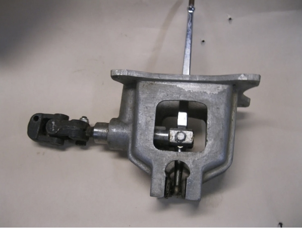
not sure I understand what your problem is. Perhaps this photo will provide some clarity for you.

if my memory serves me correctly, you should assemble the unit as pictured prior to installation  

The shift lever bottom ball should index between the two black hardened “guides” at the very bottom of the cage.

The clevis at the tip of the shift linkage rod will attach to the shift lever with the bolt through the two brass bushings

hope this helps just a little bit,

Larry


EAA14FC5-ED4C-424D-8521-19BEBF685912

Attachments

Images (1)
  • EAA14FC5-ED4C-424D-8521-19BEBF685912

Hammer???  

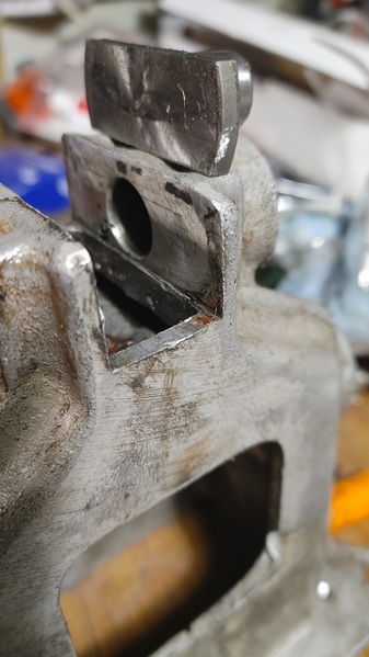
It looks like one of the pads may be out of position in the housing???

It should be a "no problemo" sort of fit!

It is interesting to see that your Goose casting is different than what I found in #878,  Yours kinda sorta has Pantera-ish features, AND Goose uniqueness.

The Goose does not have the U-joint right out the back door of the shifter housing......but rather further back on the shaft......

See if you can't put the arm in place without the shifter box in the car, so that you can see where the lower ball resides when in place between two pads.

The shifter should slip thru the hole in the shift rod....with no issues.....ie check your shifter bushings to see that they are in proper position and not out of place.

I do NOT recall where those black foamy looking things resided.....CRS disease!

Steve

PS:   In my "Oops I'm doing it again" post, towards the end pages, I found some materials that I used for the heat shields.   Check it out. If you can't locate it, ping me back......I have some of that material still.  Possibly the rivets and a die for the rivets that I had machined up..........as well.


shifter1shifter2

Attachments

Images (2)
  • shifter1
  • shifter2

Can you try holding the housing up after you put the main shifter shaft in place.....THEN from the top, drop the shifter handle down while trying to reach into the tunnel hole and finagle the shifter ball into place by moving the spring loaded pad????     My car had no spring loaded pads that I can recall......otherwise I would have pulled them out of the "blowed up" picture!

The "no u-joint" at the rear of the housing (and so much more!) prevents Larry's response from working!    

Steve

Well, attempt #47 was semi-successful...   I wedged a small piece of rubber tubing between the plates and them tapped the shifter in which knocked out the tubing,,,  seemed like I was done,,,  except I wasn't...  now the sifter moves front to rear fine, but is EXTREMELY tight moving left to right...   I have a feeling it's all coming out again tomorrow...

seems like the plates are too tight against the little ball on the end of the shifter rod...

MH

When rotating R-L L-R, the shifter lever will be pivoting on the round shifter shaft (main rod), so that rod should have been lightly greased  (in the housing also) with some synthetic lube of sorts, and the bottom ball "should" be sliding also L-R  R-L as it's movement will be 180 out from the top of the shifter handle....and this point on the sliders "should" also be lubed.....?     Also your entire shifter shaft will be rotated when you do this....so it's not gonna be freeeeely floating......  Try it from the top of the shift lever and see how it feels......but be sure that all is lubed!!!

A note that hosed me up....    Be certain to adjust your single Heim joint at the rear chassis (two Heim joint systems could be different!) mounting point so that the shift rod doesn't get hung up on the rubber boot at the firewall, and dork with your 2 & 4 shift or perhaps 1-3-5 positions!    I rebuild my ZF thinking it was majorly hosed as it was popping out of gear  (but it also was minorly hosed!!!) when all that was wrong is that I had adjusted the Heim joint height incorrectly and the rubber boot was getting pinched!!!! DOH!!!!!    The shaft takes an unusual path when it actually moves........have seen some pretty bent up shifter shafts to get it right!  (Factory bends!!!)

Steve

@lf-tp2511 posted:

not sure I understand what your problem is. Perhaps this photo will provide some clarity for you.

if my memory serves me correctly, you should assemble the unit as pictured prior to installation  

The shift lever bottom ball should index between the two black hardened “guides” at the very bottom of the cage.

The clevis at the tip of the shift linkage rod will attach to the shift lever with the bolt through the two brass bushings

hope this helps just a little bit,

Larry


EAA14FC5-ED4C-424D-8521-19BEBF685912

I think I see part of the problem, I don't have that splined coupler right off the back of the box, just a u-joint.  I dang sure ain't taking that apart as I'd NEVER get it back together while inside the tunnel!!!

My rubber hose temporary spacer seems like it will do the trick, I think there is an obstruction keeping the two plates from opening all the way and the ball at the end is REALLY tight in between the plates...  so I wouldn't call what it's doing "sliding" by any stretch.

I'll take it all out again, see what's going on with the plates and start over...

I appreciate y'all posting pics, it definitely helps to see others.  *IF* I had that splined coupler this would have been 100x easier...  Oddly, what is in there LOOKS factory...  I can't imagine why a previous owner would have made such a change...    and if they did just weld it all up, they did an impressive job!

Once I have it out again I'll post pics of how the shaft looks on the shifter end.

One other thing I just noticed, the shaft on mine extends all the way through the box and slides out the front!  I just noticed yours stops at the shifter!   Mine is like Steve posted and described.   I do have the "black foamy bits", on mine it's a single thick black rubber piece with a hole in the center.  I don't have the cup looking thing towards the top though.

Thanks guys.

MH

Last edited by mkeh

What you have is original!   What Larry posted is likely from a Pantera.

As I stated, your "housing" is slightly different than what was used in my Goose, but not by basic design and function.     The Goose got no detents or extra springs.....or the nice splined bit right behind the box!!!    ....and I don't recall any springs down in the ball area.....but I could be totally mistaken, has probably been twelve years since I visited my shifter box!  The shaft, if I recall, had to be completely removed in once piece all the way back to the ZF!

I know that I repainted the entire shaft assy, BUTT, I can't find any pictures of the whole shaft out of the car.  It was grungy in one pic.....beautiful fresh paint in the next go.......!

I like your idea of removing all, starting from ground zero!!!

Good luck!!!
Steve

Ok, today's challenge...  how on earth do you get the heater box and A/C out?  from pics I've found, the heater comes out first, but the little brace on the lower front that holds it up seems to be welded in place and the unit won't drop down enough to slide out.  on the A/C unit, is it just the two bolts up high in the rear, or are there bolts along the lower edge of the dash also?  seems like there would be, but I haven't found them yet...

She's VERY close to reinstalling the engine...  chasings hoses and belts at the moment.  I have the correct valve covers and DT Emblems, but I kinda like the aluminum ones for now

MHMessage_1672441575459

Attachments

Images (1)
  • Message_1672441575459

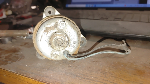
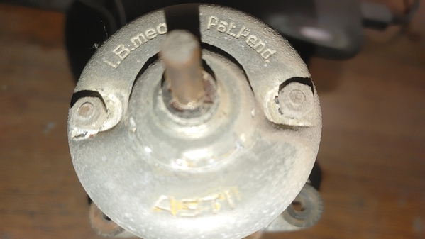
  Mike, I'm not dead sure if at that time the maker was called just "Asti" instead of later "Gate Asti", the motor number is MP3920-31... The overall number MP3920 was apparently used for years and years, the -xx number will vary with the actual spec.  But its entirely likely that yours is fine, or that any electrician could clean it up.

I also guess that the UK mini fan blade would work. The Goose heater box is 'shared' with the Mini Innocenti (the Italia version of the Mini), and then only the chimney is added on the IPRA Goose box.  Somewhere on my shelf there I have NOS motor and also a used Innocenti box...

For the AC, I think the motor is a Behr, made in Ft. Worth TX . But that basic style was used for decades (esp, 80's Alfa Spider), and even I think the retrofit Pantera AC fan solutions just may fit. Trying to find genuine 60's AC components is damn difficult, it just seems that not many cars, really, had AC...Lee

ps. btw, I think your valve covers are pretty cool, got a picture to share?

Last edited by leea
@leea posted:

  Mike, I'm not dead sure if at that time the maker was called just "Asti" instead of later "Gate Asti", the motor number is MP3920-31... The overall number MP3920 was apparently used for years and years, the -xx number will vary with the actual spec.  But its entirely likely that yours is fine, or that any electrician could clean it up.

Mine is in very good shape aside from a questionable bushing on the cage end...  Wasn't turning at all initially, now it's turning ok...  Could be better though...  The bushing might clean up. 

Thanks for the Innocenti info, always good to know possible sources if needed...

A/C investigation is pending...

I'll post close ups of the valve covers soon...

MH

For clarity's sake (and my old guy sanity!) is it possible to place a picture of the "type" of AC/Heater system youse guys are a working on???    I'm guessing that you are working on the later "in dash" AC vs the most common "underdash" version???

The conversation was throwing me, in that the under-dash system was made in Spain.... and you were mentioning non-Spanish vehicles!!!

Good stuff!!!
Steve

Steve, Mike's car is 8ma898, so almost perfectly familiar Ayacsa AC on the right  and separate IPRA box to the left for the heater...So Spanish and Italian. I haven't ever seen pictures of the in-dash solution at 8ma1100 and later.

The only reason for "almost perfectly familiar" is another twist on the AC box for Mike, where he doesn't have a glove box (he does have a glove box door...) and instead of the glove box he has additional AC vent piping to exit by the driver... But that is all a different story Lee

Well crapples...  I had a full reply typed out and got distracted and never hit send.

Quick version is "what he said"

+ I cleaned both heater fan motor and condenser fan motor and they're both working fine now...  Condenser fan motor was working before, just made an odd sound...   Also having new hoses made as well as condenser itself...    They goal is to have A/C working...   Even sourced some of the forbidden juice !!! (R12).

I might replace A/C fan motor in hopes that a newer one will move more air...

Yes, 898 has additional vents left and right under the dash by each door jamb...   and an interesting manifold of sorts feeding them...  I spoke with Bill Lavinger (owner from 70's to 90's) and he said those were factory...  He owned three Mangustas, so I knows them well...

MH

Michael,

I believe that those valve covers "could be" period Edelbrock or one of the other big names.......I have a set somewhere but couldn't put my hands on them if  you gave me another Mangusta!!!  (But I'd sure try!!!)      The logos look either custom made or modified Pantera versions not the "pork chop" version the Goose typically comes with....

I would also implore you to install a thermostat in the engine.   If you've already modified the 90 degree fitting off the front of the intake to accept a t-stat, well then good job!!!! 

Without one, you are begging to wear out your engine prematurely.  It will never warm up....to proper operating temps!  ....OK perhaps not never, but perhaps not as quickly as it should......to get your heater working ASAP for winter driving!!!

I had a think 3/8" or so piece machined up to fit between the pipe, and the intake.  It had the recess carved into it and fit using 2 gaskets and slightly longer bolts to secure it.    Worked like a champ! Quick warm ups!   NO ONE will ever point it out that it's "not factory"!!!!

Cheers!!!
Steve

Ooops! Missed replying to the AC thing.....

1) NEVER have seen AC venting at door jambs.  Yet.   Not that they were not put in place by the factory, but this is the first that I have ever seen mention of it.   Not sure what all Bill L has seen or owned, but pic's would be super!   I always wanted to put a vent on the drivers side of the steering wheel!

2) AC Fan Motor: YESSS!!!!! This is the ONE, ok ONE of the things that dearly could use more HP!!!  The fan motor for blowing cold air into the cabin fails......  I had heard of a guy in Santa Cruz that could rewind them to get more RPM's but failed to push it further.  TOOOO much apart....needed to go back together....

In the end, with new rotary pump, new hoses, lubed bushings in the condensor fan out back, and a good charge of R12.....  that AC unit blew cold air something fierce....sorta like a small kitten.......when it needed to blow LIKE A BIG LION!!!!     Many times while driving the Goose, it was simply easier to roll the window down just to have fresh air blowing around vs trying to kid yourself that that measly sickly fan motor would push enuf air to cool the cabin down!!!!

I wish I could have spent more time exploring another electric motor for that feature! It sorely needs it.

Ciao!
Steve

@mangusta posted:

Michael,

I believe that those valve covers "could be" period Edelbrock or one of the other big names.......I have a set somewhere but couldn't put my hands on them if  you gave me another Mangusta!!!  (But I'd sure try!!!)      The logos look either custom made or modified Pantera versions not the "pork chop" version the Goose typically comes with....

I would also implore you to install a thermostat in the engine.   If you've already modified the 90 degree fitting off the front of the intake to accept a t-stat, well then good job!!!!

Without one, you are begging to wear out your engine prematurely.  It will never warm up....to proper operating temps!  ....OK perhaps not never, but perhaps not as quickly as it should......to get your heater working ASAP for winter driving!!!

I had a think 3/8" or so piece machined up to fit between the pipe, and the intake.  It had the recess carved into it and fit using 2 gaskets and slightly longer bolts to secure it.    Worked like a champ! Quick warm ups!   NO ONE will ever point it out that it's "not factory"!!!!

Cheers!!!
Steve

Actually, Gary (previous owner) had that snout redone in SS and had a thermostat space included.   In Texas we don't have much need for a thermostat in our cars...   and I will definitely never take the goose out if it's bad weather...   Generally keeping it from overheating is a real concern here...  Getting the heater working is really more of an OCD kinda thing...

But...  If I were to put one in, this WOULD be the time to do so...

The cast valve covers look pretty old school, which I like...  They seem period correct for a '69 model...  The emblems are nicely done cast pieces, but their origin is unknown...  I used the 3M thin double sided tape that has the grip of death when I put them on...   So far they've help up nicely. (5 years)

MH

AHAH!!!!
You have Gary's car!   I recall him doing that now....somewhere I have pic's of what he did!  VERY NICE work!

TX weather or not, the T-stat is a smart thing to do.  Doesn't cost you poo to put in, and it really doesn't hinder keeping the engine cooler...... that's all radiator fans and water pump capacity for better "water movement".   I ran it all the way to Phoenix from CA, twice for the POCA national show, and didn't even worry about it!   If you have the original FIAMM radiator, you just need better fans and shrouding.  Put the fan switch on relays....!!!   The radiators were well built!!! Just heavy!

Still have the old C9AF-U Holley on it??  Good carb!!!  I love them....735CFM with the vac secondary and heated choke.  Put them on 428's I owned, 390, and 351s! They just work with minor jetting for proper fuel/air ratio depending on engine size.  Will need another soon like down the road!

Cheers!
Steve

@mangusta posted:

Ooops! Missed replying to the AC thing.....

1) NEVER have seen AC venting at door jambs.  Yet.   Not that they were not put in place by the factory, but this is the first that I have ever seen mention of it.   Not sure what all Bill L has seen or owned, but pic's would be super!   I always wanted to put a vent on the drivers side of the steering wheel!

2) AC Fan Motor: YESSS!!!!! This is the ONE, ok ONE of the things that dearly could use more HP!!!  The fan motor for blowing cold air into the cabin fails......  I had heard of a guy in Santa Cruz that could rewind them to get more RPM's but failed to push it further.  TOOOO much apart....needed to go back together....

In the end, with new rotary pump, new hoses, lubed bushings in the condensor fan out back, and a good charge of R12.....  that AC unit blew cold air something fierce....sorta like a small kitten.......when it needed to blow LIKE A BIG LION!!!!     Many times while driving the Goose, it was simply easier to roll the window down just to have fresh air blowing around vs trying to kid yourself that that measly sickly fan motor would push enuf air to cool the cabin down!!!!

I wish I could have spent more time exploring another electric motor for that feature! It sorely needs it.

Ciao!
Steve

I'll take some pics of the side vents and manifold...  It's definitely NOT some homebrew setup...  I'm wondering if it was a design used on the Ghibli or other such cars that DeT decided to try out on a goose... 

Lee and I both have the solid wood steering wheels...  No leather sections at all...  So DeT wasn't above randomly trying different things...

MH

Yeah, Steve, I think the improvement on 8ma898 AC venting was to remove the backpressure from the mis-applied Ayacsa unit. Just cranking up the horsepower probably less efficient: As you know, the Ayacsa unit came with 3 vents, but the right-most vent was sealed off by DeT either for looks or to somehow prioritize air to the driver...But you can see, this blocks the most optimum outlet for the air and then forces all the output thru a rather narrow neck. Note also on this  picture (the NOS, were we sleeping thread) all the holes in the top panel--clearly an attempt by Ayacsa to let the thing breathe a bit without getting noisy-as-a--clogged-vaccum-cleaner...

  Mike's car is best described in a Binky episode--a glove box door, but no glove box---instead, air tubes that take the air to under the driver's left dash...


And yes, the Cal-custom look for the Valve covers is my 2nd favorite look...my favorite is the Detomaso Weslake conversion I have only seen in a very old Ford 302 hop-up book... (see pic) Lee

Attachments

Images (2)
  • ayacsa_4
  • 70's? Weslake head  and valve cover for DeT
Last edited by leea
@mangusta posted:

AHAH!!!!
You have Gary's car!   I recall him doing that now....somewhere I have pic's of what he did!  VERY NICE work!

TX weather or not, the T-stat is a smart thing to do.  Doesn't cost you poo to put in, and it really doesn't hinder keeping the engine cooler...... that's all radiator fans and water pump capacity for better "water movement".   I ran it all the way to Phoenix from CA, twice for the POCA national show, and didn't even worry about it!   If you have the original FIAMM radiator, you just need better fans and shrouding.  Put the fan switch on relays....!!!   The radiators were well built!!! Just heavy!

Still have the old C9AF-U Holley on it??  Good carb!!!  I love them....735CFM with the vac secondary and heated choke.  Put them on 428's I owned, 390, and 351s! They just work with minor jetting for proper fuel/air ratio depending on engine size.  Will need another soon like down the road!

Cheers!
Steve

Gary & I have been friends for 25 years...  He was my co-piloto when we were racing La Carrera Panamericana in my 230SL.  In fact, around 2004 he told me he wanted to buy a Pantera and I found 898 for sale online and sent him the info...  Next thing I knew it was headed to Texas...

I bagged-n-tagged the original radiator fans and installed twin tractor fans, they work great.

I called Gary when I was wrestling with that downtube that was corroded...  He said it was a "right place at the right time" kinda thing on having that snout redone...  It was definitely well made...  and Gary likes to plan for any eventuality, so he had them add space for a thermostat.

Yep, still have the Holley carb, it ain't broke, so I ain't fixin' it...   I considered going to an EFI, but I kinda like the old Holley...   Runs great!!!

MH

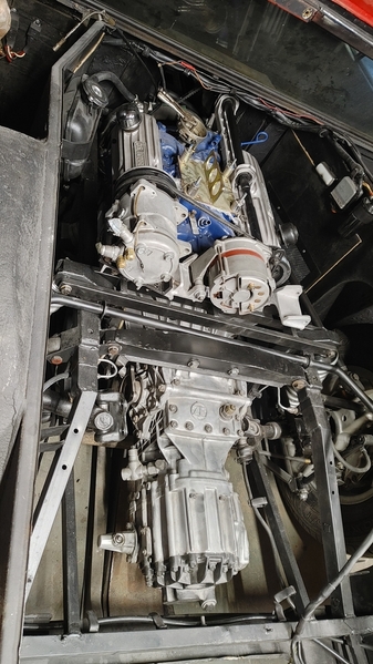
I was so tired of seeing that empty engine bay!!!   Then so stressed about the install...  Luckily I recruited several friends that are also wrenchers...  More eyes and hands are always a good thing when shoving the baby back into the womb!!!

Only issues so far were that the alternator bridge wouldn't go in until I unbolted the frame bride and lifted the ZF up a bit...  But it's in and happy...   Also, somehow when I put the shifter shaft back in i ran the rear end of it outside of the frame rails and didn't tuck it back in at the rear... and of course now I have to take apart the middle u-joint to route it properly...   But no broken rear window or damaged parts...  So I call it a good day...

I hope to have her ready to start next weekend...

Thanks to you Steve and the rest of you guys for all the tips, advice, warnings and encouragement along the way...  Front suspension is next, then off to paint and body...

The journey continues!!!

MH

Last edited by mkeh

Mike,

Ah yes, that pesky rear upper ladder bar!!!  I recall futzing with that and bellhousing or ???? removal/install!!!

Front suspension is easy peasy!
Please tell me that once you get it running AND rolling, that  you'll take it for a spin or three and see how it feels!!!!!    Perhaps you'll reconsider painting it......    

Steve

Last edited by mangusta

I'll take her around the block a few times, but she'll be in for paint soon...  I have already stripped lights and shiny bits in preparation.  I drilled small alignment holes in the spine mounts  and such, don't want to start putting all that back on until she's painted.

  Speaking of...  Should the spine hinges be painted body color or black? Should I isolated the steel spine from the aluminum deck lids somehow?  I have literally zero galvanic corrosion so far and would like to keep it that way.

Thanks again,

MH

Mike,

I learned long ago that I can't comment about "what something should be" in terms of stock paint and where, as my car had been "touched" in so many ways (see many of my old posts!) that it's not safe to use it as a gospel!

I do remember paint in the rain channels of the spine piece, and if the hinges are welded in place on the spine, they then probably were painted from the top..... from the bottom........I'll defer to others that may have a more original car than mine!!

I don't recall seeing any insulation materials between the hinges and the hatch covers......and my car was very free of hatch corrosion "that I could see".... so am thinking that the hatch steel frames were essentially grounded to the chassis via the hinges.    Any corrosion resistant treating would be between the aluminum skins and the hatchs' steel frameworks...??

Any chemical engineers out there looked under their skins? 

Cheers!
Steve

Galvanic corrosion occurs with direct contact between two different kinds of metals in the Galvanic Series, not necessarily whether there's an electric  ground. I suggest separating the aluminum from all iron/steel with a non-conducting strip that's outside the galvanic series, especially if you live in a damp climate (like So-Cal this year!).

@bosswrench posted:

Galvanic corrosion occurs with direct contact between two different kinds of metals in the Galvanic Series, not necessarily whether there's an electric  ground. I suggest separating the aluminum from all iron/steel with a non-conducting strip that's outside the galvanic series, especially if you live in a damp climate (like So-Cal this year!).

@bosswrench Do you think a layer of paint is sufficient?

MH

.....grab them gently!!!!   They're supposed to be welded........   Makes ya wonder how the XKE race alloy race car bodies were attached....or the alloy Cobra or GT40 skins were attached or insulated from...the steel chassis!!???   I'll ask another Goose owner out here that just finished his, ok...made it show worthy...enough to drive....and had to go thru the same shite!!!

Steve

Mike, yeah. pretty much once the car is assembled, the only thing you can do to avoid the electrical action is to keep it dry...and paint is at least a way to keep the metal electrically isolated. At build, putting tape over the steel is the best way, but luckily you don't have that option .

  When attached directly, DeT used copper rivets--for example the engine covers, where the support strap is attached to the aluminum trays...or on the hood at the front edge. I've got no idea how this helps, unless it drives for just the opposite of isolation (by quenching the voltage to zero maybe?)

Cosmetically, all the inside of the rear (that the driver could see thru the back) is blackened. For paint lines, the combination of 8ma1074 and that gold car show I think how the factory blackened, https://pantera.infopop.cc/top...for-sale-in-michigan , esp black over the latches, over the "roll bar" at B pillar (everything to the inside of the roof edge and up to the chrome/vinyl edging) and then covered with the gasket),  but the outside-facing channel of the spline is body color.

8ma1074 was downright peculiar with the blackening line for the hood/engine covers, esp in the way the black was carried over onto the aluminum (where anybody in their right mind would have taped at the edge of the aluminum). That and the blackening on the forward interior edge of the door...so freaky that only a factory would have done it (!) And I'd love to see confirmation in another car, so hoping that Steve's pictures of 8ma716 (before it was re-painted) agree.

  8ma1046 was original paint, but since all black not so easy to distinguish the flatter blackening...

Attachments

Images (3)
  • Paint line on the aluminum
  • '1074 right hatch
  • 1074 hood paint line
Last edited by leea

Mike,

Lee's got the idea pretty good....seal....seal....

I spoke with another owner nearby, who just went thru repairing his hatches, of rust or corrosion along the bottom edges.  When asked about the contact between aluminum and steel at the edges, he said that they found some sort of "creosote" dipped/saturated material that was between the two metals....of course by now, this material had turned to dust.   He mentioned using sealer.....but couldn't provide any further details, other than "I'm never going to wash the car....."!

As far as insulating the hinges, there is no need for this.   At the hinges, you're at steel, welded to steel (at the spine piece) then bolted to steel (at the hatch frame), using steel bolts thru all the bits.   So even if you insulated the spine hinge flap from the hatch frame, the thru bolts negate all of this!

The culprit or problem area is where the aluminum skin sits against the frame, or where it is folded over to retain to the frame. These are the areas to be concerned with.   Keeping air (contains moisture)  off of these areas would seem the goal!

I would think that the GT40 and Cobra guys would be concerned with this sort of thing also, and may be a resource to tap.    I will throw a note across the pond and check with a Goose owner who owns a body shop dealing with rebuilding  Jags and such other high end cars from the 50's-70's.  See how they deal with it!

Steve

Mike,

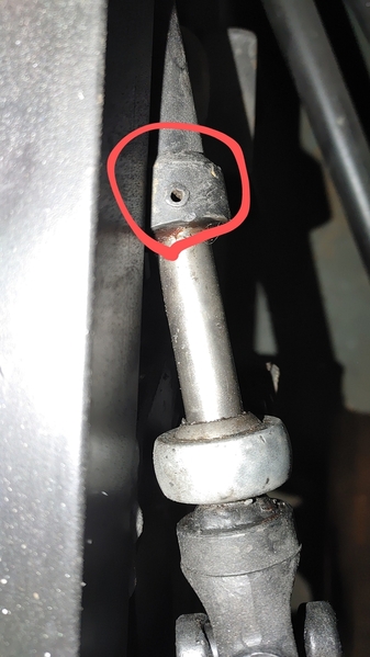
How the hay did you get this shaft out of position????

I revisited my pictures, and it looks like I never really took mine out......but I recall doing a dissection of the shifter box.... so I could be lying.....!!!   BUt in these two pictures you can see where my shift rods ran, around the shock tower and then back into the inside of the frame to the trans.

That roll pin could be a REAL bugger to tap out and back in without supporting it.  Taking the u-joint apart makes me feel more troubled......... I think we determined that the only place to get the u-joints is from some little Italian shop in the middle of nowhere...... I don't recall where....but seems like they are rare AND expensive! So grease it and leave it if at all possible?!

Start with removing the rear piece of the shaft that is adjustable, then remove the trunion retaining nut and lift it up....see if that gives you enuf?   If not, then attack the shifter box??

I'm thinking remove the shifter box and strip the shaft out of it....then move the entire shaft forward until you gain enuf clearance to tuck the rear rod back into the frame.  then tuck the shaft back in where it should be and reverse!

OK, I found my lie!  First two pic's below are before sealer/no-rust paint, where I tied up and wrapped up the errant rear section of shift shaft,  but the third pic shows that I succumbed to the need to get the danged thing out of my way, so I MUSTA popped that roll pin out....... Hate when pictures tell me that my mind is developing holes......!   You can see just aft of the rubber firewall boot that I had taped off the end of the shaft.
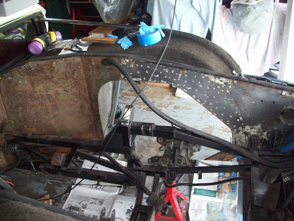


100_2697

100_2715

The shifter box is really a "not much to it thing"!    We've already determined that it doesn't have as much BS in it as the Pantera shifters.   No detentes/balls, no extra springs...
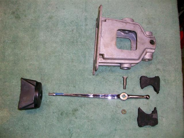
shifter1shifter2

Once the box is out of the way this would have some room to move forwards, but not certain of how much!   Certainly it could go rearward and out.....reposition rear shaft etc, reinsert....reverse!  NO HAMMERS required!!!

You needed to grease that little ball down at the bottom of the shift lever....right???

Steve

Attachments

Images (5)
  • 100_2697
  • 100_2698
  • 100_2715
  • shifter1
  • shifter2

Mike,

COOL!!!  Those pesky one way pins.....whoodakno!!!

OK, be sure not to do what I did with the center heim/trunion joint!  When you put he shifter in 2cnd or 4th check the clearance at the firewall thru-hole to make sure that you are not "too close" to the tube that passes thru the firewall.....  Mine was fine....., then I "optimized my center trunion height by eyeball.....wrongo!  I guess I lowered the shaft a bit.....

With the rubber boot installed, I ran into "too much stuff in the hole" and that being so, would interfere with trying to get fully into 4th or 2cnd gear!!!  The fix was to simply "raise" the center trunion until everyone was happy again!!!   (With no boot.....it was fine......!!!)  2 & 4 felt a bit spongy at the end of the shift...arm didn't go all the way forward in the gate.....shoulda been the first couple of clues that things were amiss!

Shifter adjustment is easy.   Center it R-L and snug the nuts a tad, then center it Fore-Aft in the middle of the shifter gate, adjusting length as needed, rinse....repeat.... until it is centered at rest, L-R & F-A. Then you should be golden!!!!

In my case, I pulled my ZF out to look for issues and magically found NONE related  to my shifting!   I did find a crazy problem with my input shaft bearing being out of place however, and I replaced 1st and 2cnd gear blocking rings whilst I was in there! So all was good!  Put it back in and didn't fix a thing!  That's when I just sat and stared at it for a LONG time.....until I traced the shifter shaft back to the firewall.....pulled that boot back and it worked fine!!!! DOH!  Adjusted the trunion joint higher......and went for a drive without worrying about 2cnd or 4th popping out of gear any more!!!!! 

Cheers!
Steve

Last edited by mangusta

Mike,

If you have the stock timing pointer and marks, you actually can see them BUTT, ya hafta put the timing light near vertical, and mash your head up against the firewall window and look directly down.......

It can be done!!!

Those new blue reusable gaskets for Holleys work very well!

COOOOOL!!!!!!!  Getting closer!!!

S

@mangusta posted:

Mike,

If you have the stock timing pointer and marks, you actually can see them BUTT, ya hafta put the timing light near vertical, and mash your head up against the firewall window and look directly down.......

It can be done!!!

Those new blue reusable gaskets for Holleys work very well!

COOOOOL!!!!!!!  Getting closer!!!

S

Seriously?  I'll have a look, but i didn't see any obvious sightline...  If I can get my old borescope working that might help...   The new roller cam changed my firing order!!!    I was surprised about that...

  My list has a ton of "to do's"...  Which includes shifting the engine over toward the passenger side...   Water pump idler pulley is about 2mm from the firewall padding...  Also have to figure out what is up with my oil pressure gauge...  It's not showing anything at all...  I pulled the gauge and ran a short to the signal terminal and it pegged...  Seems to respond fine...  Also put a VOM on the sensor and it seems fine...  Will jumper the gauge directly to the sensor tomorrow to isolate gauge OR wiring...  I'm hoping it's wiring !!!

If I need to rebuild the carb I'll look for the holley blue seals...  It's a 4150 holley...  So no worries there...l

I haven't pulled the radiator cover yet to look for an air bleeder...   So far I've gotten just under 2 gallons in her...   1 gallon antifreeze & almost 1 gallon distilled water...

I'm having a blast...  (my bank account, not so much)...

I'll post a video of her running once I got mufflers on her and a decent idle... Right now she sounds like a drunken grizzly bear...

I appreciate the help, insight, warnings and patience...

MH

Yeah, timing is set by ear at this point and I still have to source the radiator hose from the right side tube to the water pump...  Haven't found that one yet, so I slapped the old one back on...  It has a leak !!!  Possibly damaged in the shop or during the pull...  Either way, I need to find a new one...

Headers have to come back off for ceramic  coating...  I switched to the big bore headers from Hall...  Had to cut notches for the plugs in the heads.  The headers wouldn't fit otherwise.

My to-do list is getting smaller...  Front suspension is next, then off to paint & body...

MH

VAROOOMBAAAA!!!!

Mike,

Hose info to help you out.

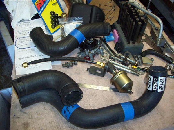
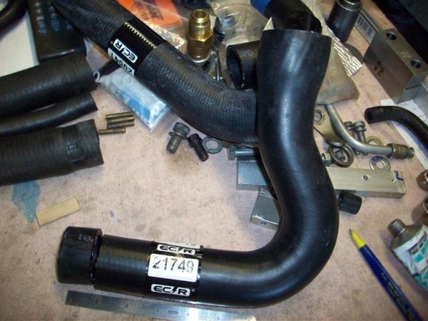
I dug this off of page 3 of my "oops I'm doing it again post"  regarding hoses.  Looks like I made two out of one for about $8....probably $16 now...!!!!  Still needed a second unique but easy to find hose as well. Read on...

"Found a Gates / ECR #22185 (O'Reilly or Rock Auto) hose of the proper 1-3/8" diameter to make the "Y-Pipe to the under car pipe" connection!     From this one new hose,  I was able to get one piece of hose that will do the job... and give me a spare to carry in the tool box... for only $8!

I cut this new hose apart, with the RH section as you see in the picture being my primary piece, and the LH section as my spare.  I found an errant slice in the area near where the clamp would go, under the label....but once I cut the hose up I ruined my option of returning it... so for $8 I ordered another and am real fine with hanging it in the rafters until needed!"  (Might still be there????)


My old lower hose is at the top of the picture....but I had no Y-pipe and wrong water pump as I found it....a total mess.

New hoses with proper Y-pipe etc fit MUCH better!!!!!

More cut and paste for "water pump to under car pipe" info from the same post!   (Gates / ECR O'Reilly) #21749- I think this may be the stock lower hose for a 67-69 small block in Mustang /Cougar models.

"Needed to do just a tad of trimming to get things to line up and not bind.

I took one inch off of the lower end. It should be noted that this hose is 1-3/4" at the top and 1-3/8" at the bottom, just what doctor DeTomaso ordered!!!"


Hope these number help you out!

Steve
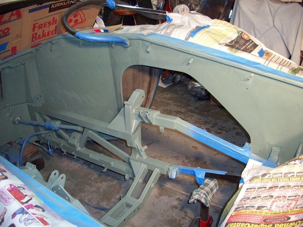
Wow, that is VERY useful information.  Got a list of belts in that collection of data?  I've tried several sizes and profiles and am solid with the water pump & jackshaft belts up front...  The Alternator belt is the right length, but I think it's too wide, not fully seated in the pulley...  the A/C belt i'm still messing with...   All Gates Green Stripe so far...

Thanks for the part # on the hoses...  That is going into my archives !!!

MH

Mike,

For the alternator you may need to go down to 7/16" width or perhaps even one fraction next smaller.   I don't recall what that particular dimension was....

Otherwise, for AC belt and an Alt belt, here is where my expertise falls......as my car had the alternator mounted on what would normally be the smog pump wing of the bellhousing!!!  SOOOOO, I must defer to the masses to follow up here!

TO make matters less fun, I checked my "alternator pictures" out from various cars, and found at least 3 different rear jackshaft pulleys in use!!!! 2 sheave and three sheave!   I also wonder if I didn't see at some point in time, a belt running the AC pulley which then back fed on a second sheave to the alternator!!!  Talk about "your mileage may vary!"

Since that part of my rebuild had already been figured out during prior engine swaps etc, there was no change in belts this time!

Cheers!
Steve

Mike, I spent a little time yesterday looking for cross-references, the Gates numbers are easier to find (but strangely, I haven't found cross-references against the Pirelli numbers...you'd think with Google, this would be easier (!) Esp, elusive is the Pirelli 261206 belt (for the alternator).

The "AS small pulley" is interesting, I assume this differentiates the large radius drive on the jackshaft side for the Anti-smog pump (and who ever calls this the "Anti-smog...). But I thought thought that was a transition that came later (so strange its in the owners manual, which I assumed was printed once, before such a transition)...

(minutes later; take back my words, how could I imagine there wasn't such a thing as a revision (!) An earlier owners manual had very helpful empty boxes for the user to fill in their answers for the drive belt....and on 2nd to last page, instruction for the oil and grease was just "Oil: winter, summer" and not MOBIL). The photo I copied was from 8ma1134 (still on ebay after ~2 years, I think) --Lee

Attachments

Last edited by leea

Sorry, nothing to offer, just that I hope you can solve it.

I (shamefully) run an AutoMeter unit in place of the OEM gauge.  It absolutely TRASHES up the classy vibe of the Veglia dash.

I suppose you could send it to a gauge rebuilder but if the issue lies outside of the gauge, in the cable or the sensor then I suppose that wouldn't help...

Good luck! Great thread to follow. Thx for posting.

Sorry @scifi, I guess I deleted my last post while you were replying to it.   I called the manufacturer and they knew the cause of the issue and gave me the solution, so I deleted the post thinking no one had seen it yet...

For those that didn't see the post, I replaced the points with a Pertronix Ignitor 3 unit...  Runs fine, but the tach was reading about half of what it should be.  I checked their website and they said *if* your tach reads too high to add a 10k 1/2w resistor in the signal wire between the coil and tach.  But nothing about reading too low...   Turns out the resistor is effectively a signal stabilizer and should fix my issue as well...   I should have verification over the weekend...

@scifi do you have your old veglia tach? The fiat 124 spider tach is a veglia and the same internals as the Mangusta tach...  Have you ever been into the Veglia's?  Pretty simple stuff...  5 of our gauges are pretty much all the same, just a different face plate... 

MH

Well, adding the resistor was a no go...  Tach didn't work at all with it inline...   At idle it reads a little low, but the problem seems to be exponential with rpm's...  Idle shows around 600rpm, but 3000rpm reads around 2000 and 4000 reads around 2500rpm.  The manufacturers website also mentioned using a capacitor...  I will call them on monday to see if they think this will help...

Meanwhile, I started on the front suspension .  so far I've found the offset spacers on the drivers side upper control arm heim joint completely shot...  Passenger side is perfect...  This explains some if the odd noises I've noticed in the front end.  Luckily, I do have grease fittings on the upper ball joints...  Not sure if they were original or added...  But happy to see them.

More tear down monday !!!

MH20230216_143324_HDR20230216_143329_HDR

Attachments

Images (2)
  • 20230216_143324_HDR
  • 20230216_143329_HDR
Last edited by mkeh

Mike,

2/19 Edited to correct incorrect memories!   S

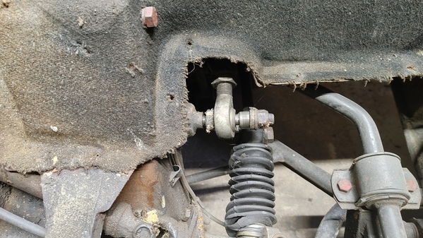
I will say, that is the oddest looking bad front a-arm Heim joint affair I have ever seen!!!!   My Heim joints were bad, but NOTHING like what you have........ It just looks like there is too much shaft sticking out for the nut to hold anything together............even if all the proper parts were present????

There a long shaft that passes entirely thru the front shock tower and fastens to both heims??????   Check the other side to see what is whacked there?

It's been so long since I've been in there............ likely one of the first things I ever did......was grease the squeakyFront Rebuild_00006Front Rebuild_00007Front Rebuild_00010Front Rebuild_00011 LOWER front a-arm bushings......later doing the ball joints after the stock ones self destructed...... almost lied and said that I didn't have a digital camera.....what I DIDN'T HAVE was recollection of these particular pictures which were stuffed in a "misc" labeled folder....DUH!!!

Pics of new LOWER inner bushings from one of the vendors.....really the originals weren't bad apparently!!   The "needle" grease gun tip to grease Unibal heims.

New Unibal joints all lubed and bootied up, ready for new ball joint and installation!

Close up of the reinforced lower a-arms that some of the cars got somewhere in the late 900's or early 1000's???     My car came with one of each due to an accident......and this just happened to be the newer piece!   I modified the other side to have a similar reinforcement job done!   Requires one longer ball joint bolt on each side.....

Plews needle style grease gun fitting for the Unibal heim joints!

Cheers!!!
Steve
Attachments

Images (4)
  • Front Rebuild_bushings
  • Front Rebuild_finished
  • Front Rebuild_reinforcements
  • Front Rebuild_needlepointgrease
Last edited by mangusta

Mike and Scifi, when I had way too much time on my hands I fit a stepper motor tach into a Veglia can (and then got 90% finished with an Odometer, all for no good reason) https://pantera.infopop.cc/top...43#19905352124810043

Mike, I can only assume that the trigger for a Veglia is a strange timing consequence of the particular "monostable multivibrator" circuit, something I never quite figured out at the transistor level...Really, once connected to the the coil, you'd think that a trigger is a trigger is a trigger--but even on this blog, it seems a common experience to see a moving but inaccurate tach read. Maybe my stepper motor tach wasn't a complete waste of time...

  Yes, a tach amp like this https://www.ebay.com/itm/142171581596 may have solved the tach on my 308 that wouldn't work after I put in the Electromotive ignition...and may be worth a try. But you know, the Pertronix "should be" working now...Lee

Mike, if anything, I am fabulously happy with the undercoating texture in my wheel wells but yeah, I felt like I was standing on my head looking at the pictures here...

  Here is a closeup of the alignment spacers on the upper A-arm--as used on the other Heim joints. There is no compliance in the upper arm, only on the lowers (which I remember getting from Hall). (and yes, ignore the direction of the nylock, here just serving to avoid losing the pieces).

  I needed one or two of the spacers, luckily found a machinist willing to make them...In the picture below, I cannot remember which was the exemplar and which the copy (but guess the original is far right).

The naked rods are also shown from an 8ma6xx car below (when the car was Al's and more perfect pieces were installed...and yes, that precious Mamut terminal block has been reunited back with its proper owner ).

Attachments

Images (6)
  • 8ma1076 front suspension
  • 8ma1076 front suspension
  • upper A-arm rods (and other pieces) from 8ma6xx
  • alignment spacers
  • Goose misalignment spacers
  • front suspension
Last edited by leea

Ok, front left suspension removed...  The rear nut on the long double threaded bolt through the A arms had completely come off and the bolt was in the process of working it's way out !!!  It appears there was no damage, but I'm still cleaning...

I'm in the process of sourcing the 40mm fiat 124 ball joints and the Fiat X-19 tie rod ends...  I'm hopeful the front end refresh will go smoothly and quickly so I can get her in for paint & body soon...

Still haven't resolved that tachometer issue yet, but will experiment with a potentiometer to see if another resistance value will get me reading right...  If i can find the right value, I'll put a VOM on the potentiometer and use a matching resistor...  If that's doesn't work I'll try capacitors...

Bit by bit...

MH

Mike, if the tach is only "wrong" but working, it could be that just turning the trim pot in the Tach brings you whole...the tach/speedo are easy to open up (unlike the 2" gauges),  the guts are not fragile or uncommon. It seems that some others just suffered noisy battery voltage to the tach (so a big cap on the Battery line right at the tach just might help, even an inductor/capacitor there). Since the tach triggers on that high voltage spike, its hard to know how an external resistor or capacitor on the Tach line will do much, but who knows...

...and then comes the paint and body?

I've been looking at the pot trim...  I have a laser tachometer that i can use to calibrate with...  But I haven't messed with it yet...  I was hoping for a simple solution ...   

Yes, the tach & speedo are easy to get into compared to the smaller ones for sure...  The smaller ones aren't too bad...  Just have to be patient with them...

MH

MIke,

Pic of Ball Joint from the factory circa 1996.... cast body vs stamped temporary steel....!     My ball joints self destructed into multiple fragments....sorta like your a-arm bolt/nut affair!!! (That thing musta done all sorts of bad things on the roadways!)   Hopefully the shaft will clean up fine!

I need to defer to others and their posts.....whether this be the "big" one or the "small" one (upper(less load) or lower (more load) depending on A-arm/spring design!)......but what you shouldn't need to do.....is grind anything to get things to fit!

My crusty brain thinks that the Fiat Mechanic nearby told me..."they were a 124 Joint.....".

The tie rod ends should be standard X 1/9 items, untouched by DeT!

Progress!!!

Steve

Attachments

Images (1)
  • Front Rebuild_00002

@mangusta luckily the long bolt was still doing it's job...  The nut had come off and the bolt was sliding forward...  Not sure if all the access panels kept it in place, or just luck...   Either way, i'm glad it was still there...

Apparently the X1/9 had several tie rod changes over the years, but I did find a thread on here with the part # (might have been one of your threads!!!)...

Most of the previously listed sources for the ball joints no longer carry them, midwest-bayless.com THINKS they have the 40mm...  They are going to check it and let me know...

MH

For some historical part numbers again.....!

C. OBERT & CO. (FIATPLUS.COM)
#0005880297N Lower ball joint kit.  He had about 40 in stock..... "  (This was about 10 years ago!)
<form action="cart.php" id="orderform" method="post" name="orderform">
Part Number: 0005880297N    40MM DIAM!
Weight: 2.00 lbs
Model: FIAT DINO/MANGUSTA/1500 SEDAN
desc3: /124 SPIDER/124 SPIDER 2000
desc2: /124 SEDAN/124 WAGON/124 COUPE
</form>
Outer tie rod ends are for a Fiat Dino and are #0004100024N.
And also used in some form on the X1/9's.
Last edited by mangusta

It seems tie rods for Fiat 125 and 1300 work (and well, those are also common for the stub axle itself...). The tie rod is male thread.

And it seems that also ball joints may be shared there also...Mr. Fiat, etc--  https://www.ebay.com/itm/313984785167 or

https://www.ebay.com/itm/13439...tkp%3ABk9SR9LOva_OYQ

or

https://www.ebay.com/itm/13413...7Ctkp%3ABFBM0s69r85h

All in all, more likely a fit is from Fiat 1300/1500 than the later Fiat 124 (esp because well, the parts manual points there !

Last edited by leea

Fiat Plus had the tie rod ends (I ordered them) but only one 40mm ball joint...  He was putting the hard sell on me to modify my A arms to fit the 43mm ball joints...  I'm not sold on modifying the original A arms though...  Seems like a risky move considering the load they carry...

I've located Fiat part# 5882118 in the UK, Ireland & Italy, but NONE of them ship to the US...   and their websites ALL seemed oddly similar...

So...  Tie Rod ends located...  Still searching on ball joints...  Mr.Fiat was a no go...  Still have a few calls out, so still hopeful...

MH

Last edited by mkeh

Add Reply

Post
×
×
×
×
Link copied to your clipboard.
×