

Jack,
I'll see if I can find some 1/16"ish roll pins to fit in the center of mine!!! For some reason, you only hear about this problem with the Clevelands by and large...... Only guys in the years I was in the Cougar club with this sort of problem were the 70+ cars with the 351C.....bizarre.....
Well, I am still waiting to get time on a lathe, to doctor up my jackshaft. I need to remove some metal to allow the new pulley to fit back far enuf to line up properly with the water pump pulley and idler. I also want to adjust the areas where the bearings should slide on with little but tapping with a rubber mallet...being ball bearings, this should be sufficient! They do not need to be a tight press fit.
Once I can get this done, I am on to bolting down the intake, fitting a hardline from the fuel pump to the carb, drop in the distributor.......and PUT THE ENGINE IN THE CAR!!!!
But first...gotta get time to go to the neighbors... and use his lathe!
I finally got the 4.6L engine project done. After all that work, we fired it up and promptly ended up with water in the oil again!!!!!! AAAAHHHHH!!!!!!
Short story.... after checking and finding the compression tests to be good.....I used a coolant pressure tester to find that there was a leak...duh....! I pressurized the system using my air compressor (dialed waaay down) and a stethoscope, and found a hiss under the valve cover.
Removed the valve cover and found a geyser out of the LH block freeze plug!! You can just barely see the freeze plug behind the chain guide in the picture back up a few posts. It will be the one in the RH side of the picture down in the block.
I replaced both with brass. Only the one had a small hole in it, up on the top edge, so while standing and working on the block, you would never have seen it!!!! Just that tiny spot on the plug was bad...the rest of the plug was as solid as could be!!!! Other plug was solid too! Very strange! Anyway, put in brass replacements, put all the chains back on, the front cover, and fired it up! Holding pressure now and runs smooooooth!!!!
Gotta go get it smogged next week!
So, just when I think I'm getting ahead of my car projects...the daughter pulled up in front of the house tonight in her old Lincoln Mark VII......and asked me if "orange stuff" should be coming out of her car.......! "No, nothing should be coming out of your car......(now what?)" Bad water pump.....ugh.
It never ends.....
Steve
Progress, digress.....story of this project!!!
Finally got my jackshaft in the neighbor's metal lathe and trimmed up the front nose so the front pulley will line up. Removed a step in the middle bearing area and cleaned up all three bearing areas so that the bearings slid on with a firm grip but no malletizing required!
Installed the front and middle bearings, but when the shaft was installed, the rear bearing hole was far from centered on the shaft! This bracket is anything but straight! I worked on it a while with a rubber mallet but was unable to influence the shaft to center much better...need a bigger hammer....but I resolved myself to simply run the front and rear bearings for now.
The only way I could figure to fix it would be to press or malletize the bracket so that the shaft bearings line up properly. THEN, machine the 4 mounting bosses flat..... I'll take that on next time the bearings go out.....in 20-30K miles.....! I'll probably regret this decision then....but I need to move on.
I had been working on rough drawings of a new throttle cable bracket...one of those "oh crap I forgot all about that part" things that you encounter once the engine is nestled away in the engine bay, your buddies are all standing around drinking your beer, waiting to "fire this bad boy up"....but you don't have a throttle cable bracket...because the old one doesn't fit!!!
Old one (slightly cut up....was into the process before I got the camera out....)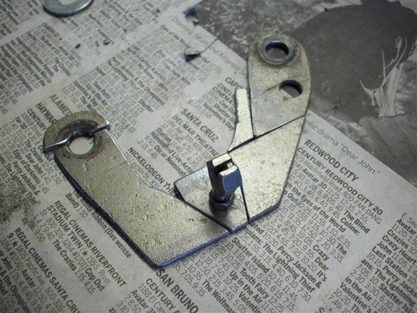
Here is my jig for setting up where I needed the new bracket to hold the little cable retainer: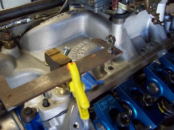
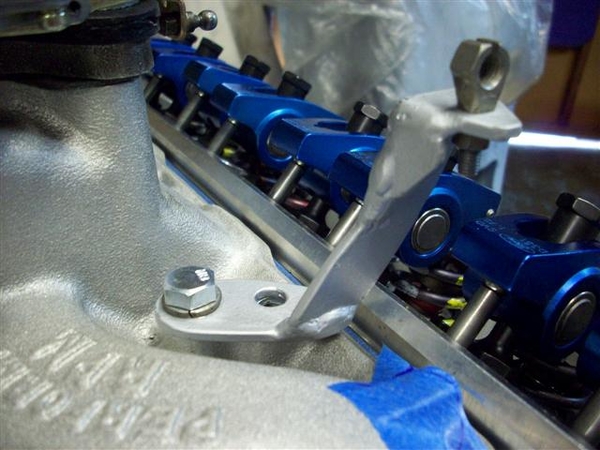
After lots of work with a hacksaw and hand files, here is the final result!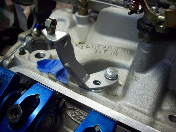
Also hit the parts store yesterday for belts and hoses. Brought 4 belts home and got one good fit, one "work in an emergency fit" for the water pump/idler belt. Struck out on the jackshaft belt...but know what I need now.... I will post numbers in the TECH section once I finalize them.
Also struck out on the hoses for the water pump to the lower metal tubes (to the front of the car) and for the "Y" pipe to the lower hose. See my post for info in the Tech Section of this forum. I looked through their entire stock (not fully stocked....) and came up empty. I know I did this last time and came out a winner..... Oh well, those will be some of the last things connected...so have some time.......
Today? Not sure...maybe install the intake manifold.....! I think I'm almost done modifying it!!!
Have a great 4th!!!!
Steve
Attachments
Images (4)


July 5th....back to the parts store to check out belts....that only took two trips....second belt for the jackshaft pulley was still too small...so called and different sales clerk found me one in between...but this now the smallest increment available....no smaller ones or larger by just a smidge! (OK, at least in their system....)
Ended up with a Gates 13A1230 #9485 (13mm wide, A-type groove, and 1230mm long)
It fits OK, but the adjuster is out towards it's edge. The 13A1220 just wouldn't go on....but then I didn't get postal on it either....! It will work.
With no more to actually do to the intake, jackshaft, and upper end of the heads and block, it was time to install the intake! Cleaned up the gasket surfaces of finger prints and any dusty bits, applied cork end seals to block (double sided tape on them!) set the special Felpro gaskets (for the SVO heads) down and applied sealer (the Right Stuff) in the corners.... Lubed up all of the fasteners with anti-sieze and went to town on the intake!
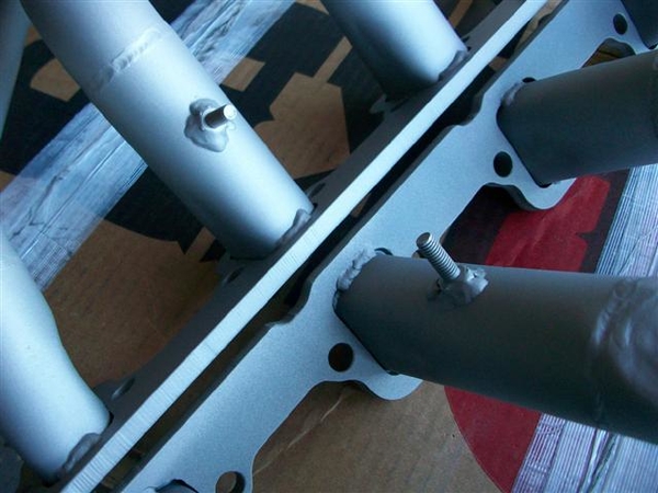
First thing that pops up, is the fact that you cannot, no how, no way, with the tools that I have at hand, and that's a pile of them, can I get to the center two intake bolts to torque them down!!! The jackshaft bracket just gets in the way of making this a reality!! So I tightened them down a bit without the jackshaft bracket in place, then put the bracket on, tightened the rest down to spec, tried to get a wrench in to torque them some more...eventually removed one rocker arm to get some swing on the wrench....but it was faster to remove the jackshaft support, torque the middle two bolts down, then put the bracket BACK on and torque everything back down again........ I finally got it to the point where the gaskets were compressed, and the tightness of the bolts were at spec....what I ball buster mentally! "Is it gonna leak now?" Of course not.....
With the top end on, it was time for the oil pan. No more opportunities to pull stuff out of the engine if it gets dropped inside! I am using one of the whippy dippy one piece silicon pan gaskets that another club member gave me, as his project went from a 302 to a 351...... Thank-you very much, it fit fantastic! A little of the sealer in the corners, set it in place, and where the hell are the pan bolts???? Found a new set....oh crap, only 4 bolts fit! They're for an FE Ford.....back to the bolt buckets/boxes.....found a set of stock ones...... Installed them...but short one small one!!! Back to the box of "Ford" bolts....problem solved...pan is good-n-tight! I really like the one piece thing, being silicon, they installed little shims around the bolt holes, so that you cannot over tighten the gasket and squish it out! We'll see how she holds up after some miles!!!!
Installed the new dipstick tube, and for grins, dropped in the distributor. Looking like an engine finally! (Distributor will need to come back out for priming the oiling system. ) Also installed various fittings for water/heater with sealer, vacuum fittings...getting the small things out of the way!
Time to start dealing with carb fitment. Have a couple of slightly used Holley carbs, a 570 Street Avenger, which I believe will be fine, but I believe it will leave some performance on the table...so may opt for another 650 that I have set aside. The 570 was jetted very small on the primaries with #54 in them and a pair of 65's out back.....I bumped that up to a 65 primary and 72 secondary. (Ford ran a 66/71 combo in the 1968 GT350, which was a mile motor, so we should be close!) It should not run lean. 8.5 power valve....which may need to go down in value if the cam turns out to not have good idle vacuum. Used re-usable carb gaskets to make that task easier.......should I need it.
The 650 turned out to be jetted much bigger, at a 67/73, so would have worked ...but just a tad rich perhaps......all would depend on what the larger venturis permit in terms of fuel "mixture".
Started bending up fuel line for the pump to the top of the engine....but want to see if a local shop can do "double flare" joints in tubing... if yes, then easy cheesy! If not, then it's grunt and groan with the hand flaring tool....ugh!
Here is a shot showing the fuel line, as yet untrimmed to merge with whatever I make to drop down out of the carb....I should have backed off a bit....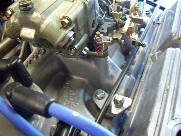
Tuesday night was carb puttering...ordered carb fittings for 5/16" line. 3/8" line is just tooooo big for such a little motor....
Last night: header puttering.....two sets of aftermarket header and neither pair fits well. I am guessing that I have two sets of Hall "big bore" Goose headers.
One set (silver in the pic) has doinks on the front most tube where it looks like the top bar of the LH suspension hit it...second tube may have a mark too....that cannot be good. At least you can get all the bolts in! I may chop out a section of tubing and re-route it ever so slightly.....if I can find some tubing.....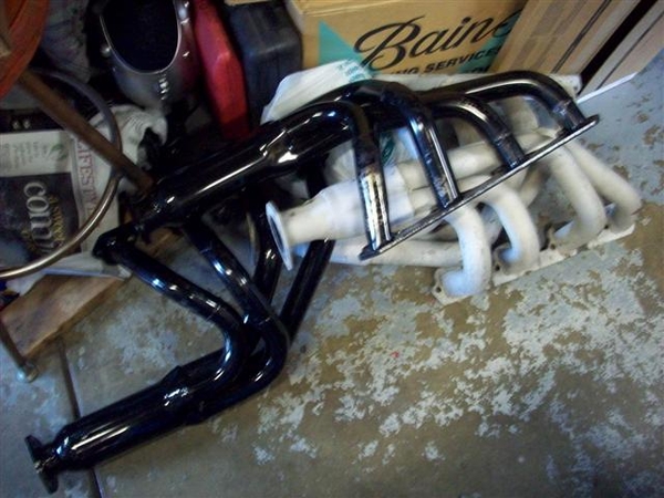
The second set, black in the picture, turned up with one having been installed and actually run, and the other was a virgin....never seen a bolt or carbon trace in it's life yet..... I can see why! There is NO way in hell that you could get a header bolt, or nut if using studs, to fit given the way that the tubing was welded in place.....not gonna happen!
Idea is to see if both headers fit to the muffler at the same point in space. I will then send the best fitting set off to get either Jet-Hot coated or alumi-coated....one is mo' better...gotta look it up.... then install the other set to drive around with until the headers come back from the coater!
Picture isn't too hot, but you can get an idea of the angle that it was coming off of the flange.....
After spending a couple of hours on the pair, I got them to the point that I can get a 1" header bolt in without too much difficulty, but more importantly, I can get a wrench on the bolt heads now!!!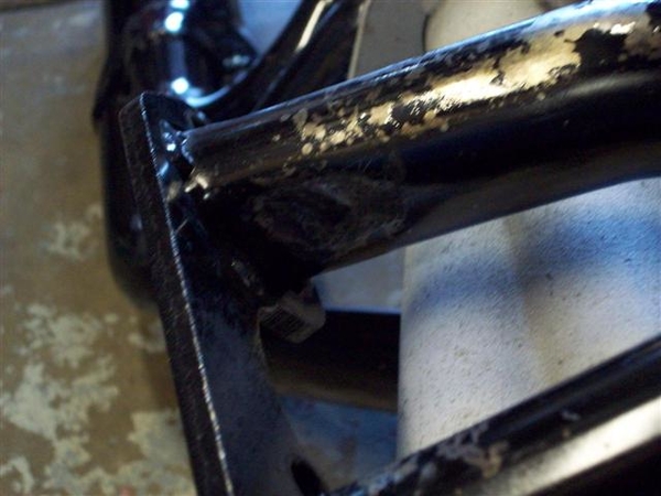
One side had at least 3 spots that needed malletizing, the other at least two....they were just a horrible job done.....!
Fast forward to tonight, July 8th.
Tonight I put the new bowl fittings in and buttoned up the carb. Checked things out, blew out the passages....
I installed the spark plug wires.....which turned out to be a BREEZE!!! Turns out the spark plug wires are numbered.... well duh! That sure took all of the fun out of it!!!! This is a late model firing order, so it is the same as a 351. 1,3,7,2,6,5,4,8 I do need to drum up some 9mm wire separators/retainers.......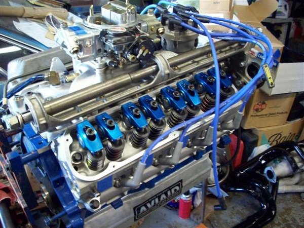
Here is something else I knocked off of the list.....something that few of you probably think of...but after reading a couple of recent posts from guys about problems with the ZF's in their Panteras, AND because it is so stinking simple..... there is no excuse... Lube the pivots on your ZF throwout bearing shaft! A half shot of grease should be plenty, wipe off the excess.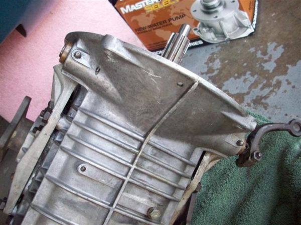
This is the bottom view of the ZF....in a Goose!
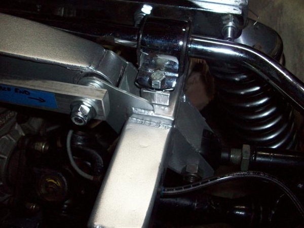
A LAST chore for me, is to machine down my T-stat adapter to 1/8" thick from 3/8". Turns out that the 90 degree heater bypass hose gets too close to one of the lock nuts on the jackshaft bracket where it attaches to the front idler bracket. Last thing I want is a blown $5 hose because it rubbed through on the $1 nut..... I was just going to put another hose clamp around it....but decided to go the longer road....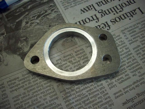
I believe that I can run stock Ford bolts to hold this together, with two gaskets...and the shorter spacer may allow easier wrench/finger access too!
I also had to file down a boss for a timing pickup that the late model replacement timing cover has on it. It appeared toooo close to the lower water pump hose that will be drawing water from the front....radiator. Again, I didn't want anything chafing, so filed the sharp edges off, reduced it's height/length, and polished it up a bit to smooth things......nothing sharp......!
So now my shopping list is FINALLY growing smaller....
30W break-in oil....12 qts should be enough for break-in and first oil change. After that, we move back to Mobil1 either 10-30 or 20-50.....
Fuel line to make "crossover" line to feed rear bowl.
Hose- to connect y-pipe to chassis tube. Still haven't had a chance to try a different store to check it out......
Also, header bolts ( I have a stash, but they are all used, and I don't want to risk buggering up the aluminum threads.....new bolts "should" be clean!) 1-1/4" long studs for valve cover mounting, some nylock-flanged nuts, and perhaps some nylon flat washers (good to 350 degrees!) to seal up the holes in the valve covers when tightened!
Just remembered one more thing! I want to replace the short straight junctions of rubber hose up front to the water tubes, with Gates Green Stripe super duper hose! Need to do that before the engine goes in.... I guess I don't have to...but if I want to fire this thing up....the sooner the better!
Charge the battery....and get a couple of gallons of gas....!!!!
Ciao!
Steve
Attachments
Images (7)


I forgot to mention that after torquing the intake and jackshaft bracket down, that it did little to help with the alignment of the middle bearing!
Measurements show that the centering top to bottom is about .035" or so off, closer to the top than the bottom, and also from side to side. Outside is closer to shaft than is the inside of the bearing bore. Also around .035"ish.
It is enough in those two planes that I don't even want to try to make a middle bearing work at this time.....would certainly be interesting to hear what the factory did to make these fit properly!!!!
Stopped by the AP store at lunch, grabbed my oil, some more 5/16" steel fuel line, and also picked up a couple of candidates for one of the lower coolant hoses......
Off to Fastenal later for some bolts and such!
Ciao!
Steve
Couple of more details to finish.....and the engine will go in later today or tomorrow!!!!
Finish steel gas lines to carb
Machine down the spacer for the thermostat (custom made adapter....to correct a DeT deficiency...or oversight..or...?) and install it.
Dump in some oil and prime the system by hand, reinstall distributor.
That is my short list......
So later today, or tomorrow!!!
Ciao!
Steve
DeT Deficieny? No, really...Baw ha ha ha
Your car is coming along nicely, love the updates! Can't wait to see the car when its done! (I'll bet you too) Are these cars ever done?
Curt
Your car is coming along nicely, love the updates! Can't wait to see the car when its done! (I'll bet you too) Are these cars ever done?
Curt
Steve, this post may be too late for you, but what works on most headers on aluminum heads is to use 1" or 1-1/8" long allen setscrews and stainless hex nuts in place of header bolts. Not only are the setscrews gr-8 but if anti-siezed, they won't let the nuts freeze up. You can use reduced-hex jet-nuts for even more wrench clearance on 'difficult' header places. Good luck getting noise outa the thing this weekend!
Jack,
Good suggestion on the header bolts thing! I may just do that. I just can't believe that anyone actually made these headers the way that they did....there was NO WAY that you could get any nut on a stud, or a bolt in a couple of the mounting holes...
I am using the stud thing for my valve covers. I bought 1-1/4" but they will be too short....(I purchased 1 of the 1-1/2 pieces and it fits great. Doh!) Special nylon washers are coming as are flanged nylock nuts! (I LOVE having a Fastenal outlet just down the street from the house!!! They have TONS of cool nuts-n-bolts and screws in their catalog! Their metric selection is outstanding!!! ...not always in stock, but they can order anything....)
As I mentioned, header fitment will be one of the remaining "chores" as the exhaust pipes/mufflers that I got from Dana at Mangusta Int'l were shipped with the inlet pipes unwelded, so that I could place them..... I guess I should open the danged box and check them out!!!! (I've been resisting...so that I can play Christmas in July......or "late birthday".....!)
If I can get the engine in place tomorrow (spent all day today getting my t-stat spacer machined down, putzing with the steel hard lines to the carb, and priming it with oil.)
Currently I have one bend and a flare to complete on the carb transfer pipe (primary to secondary on the 6150 style Holley) and then I BELIEVE, that it will be ready to hoist up and in!!!!
I did find a Gates hose for the lower Y-pipe to the under car pipe. It is a #22222 and only will need a minor trim to work properly!! Couldn't ask for a better fit!
Put the T-stat back in and finally installed the Y-pipe to the front of the motor as well...
Since my car had a hand made over flow tank for coolant, I spent some time cleaning up the new original tank...getting it ready to mount up when ready!
Are your tanks just held in place by the bracket, or are they wrapped with some sort of insulation material????? Seems like my clamp will leave the tank "just a little loose"....
Will post some pic's later tonite.
Back to tube bending 101....!!!!
Steve
The next rebuild will be SO much easier.....!!!!
OK, picture posts! Engine sits waiting for hoist connection and "drop-in" tomorrow! All the small work that I can think of for the moment is done....
Fuel line fitting is complete.
Side view of lower line.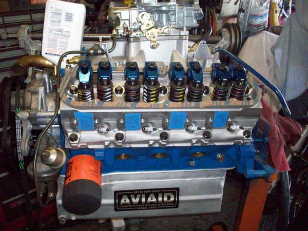
Closer- good view of the oil sender extension fit. Valve covers will go on once the engine is in place. Newspaper is to keep crap out of the 3.5 qts of oil that are in the pan after priming it..
Shot of the top section of the hard line splice. Got much better with my tubing flare kit...after I found that greasing the various bits and oiling the threads of the forming/pushing tool made things work much more smoothly! (we'll see how good I did once we pressurize the fuel line!!!)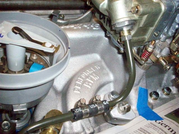
Here's the carb balance/feed tube that I formed up, and new bowl fittings for the 5/16" line. I used a Dominator front bowl, which has two threaded inlet holes on it, like the old factory Ford Holleys used on the 390GT and 428. On those, the line went under the choke housing.... I had to go out and around the side, plus over the top of the jackshaft bracket!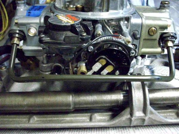
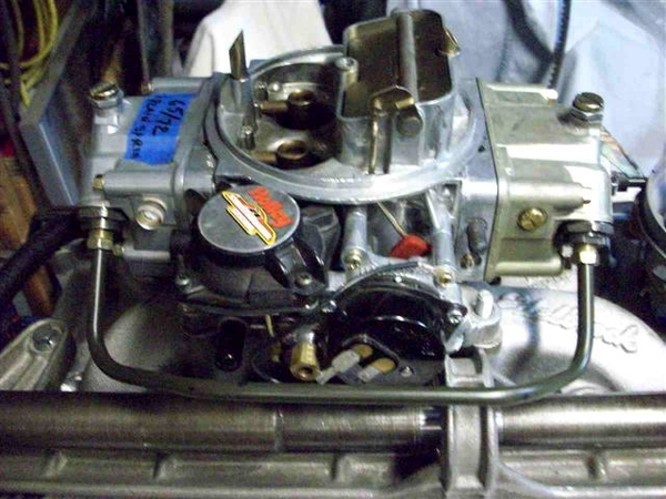
Front view. Watch out for the "hot connection" to the choke!
Special coolant "Y" pipe that was found in the Goose. I copied an original in heavy wall (thin wall would have been fine!) stainless last time around...as all I got with my car was about a 3" piece that was in the final stages of rotting away...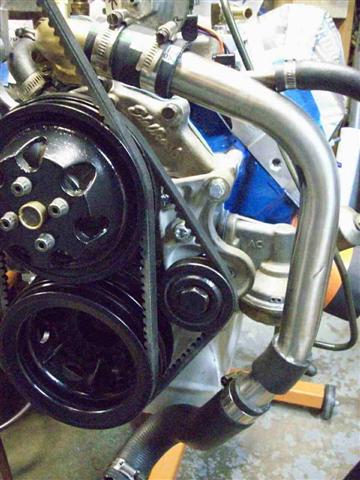
Top view where it attaches to the special thermostat housing (which houses no thermostat in the stock form....) and you may just be able to make out the thermostat adapter, which now measures a much thinner 1/8"!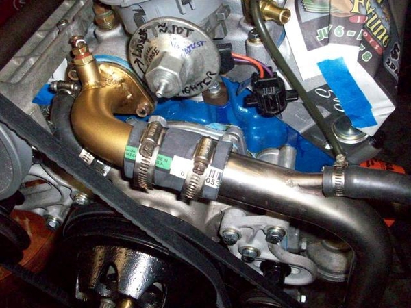
View from the top side.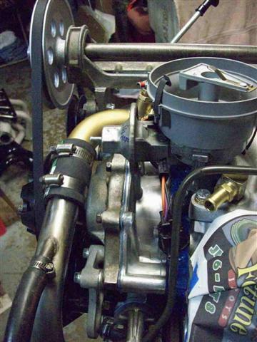
View of the RH side, water pump inlet where I had to remove material from the timing cover fitting for clearance.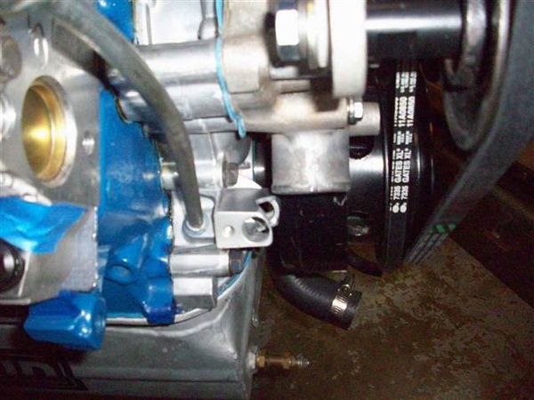
Same view from a little further back. Front jackshaft bracket attachment can be seen. Dipstick bracket. T-stat spacer in place.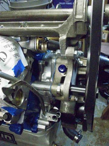
Rear of the intake manifold where I had a piece welded on, to attach the rear of the jackshaft bracket in the stock manner. Only the stock cast iron 1968-1969 type 4V intakes have the boss for this as far as I know. Good shot of my custom made throttle return spring bracket on the left side of the picture, the PCV hose & fittings, and the vacuum hardline tube for the power brakes. This tube will be bent up a bit more to flow around the head. It's still in it's form as removed from the old engine.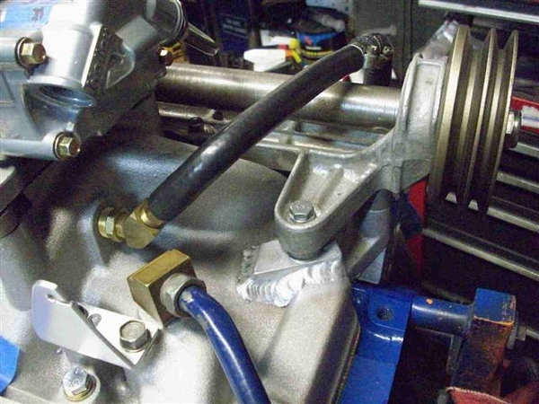
Just a view of the business part of the jackshaft feature.... I wonder about the belt fit....the adjuster is out to the extent of it's extension!
Back at it later today!!!
Steve
Attachments
Images (14)


Well, the engine is resting in it's new home!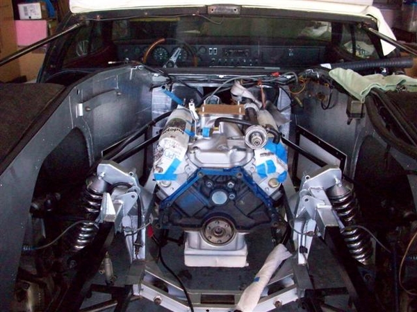
A few things didn't go as desired....
New fuel line protruded just enough at the bottom bend that it hits one of the braces that connects the top chassis rail to the bottom rail....working on reforming it...
Oil filter must be installed AFTER engine is in place....now I know why the previous owners installed a remote filter on my other engine.....
Oil pressure sender stand off was NOT the correct one! DOH! Had to remove the sender to get the engine to set down.... Will need to install the shorter stand off I guess!
Would love to see pics of your oil sender area if you have an engine out!!!
Here are some pic's of how we got to the shot above!
Trying to get three types of chain to fit into the elcheapo load balancer for the hoist...which has a loop on it that doesn't allow "easy" looping of the hoist cable thru....so that we can get enuf overhead clearance in the garage with the old flip up door open! Of course the heads have both 3/8" holes and 7/16" holes and not all of the chains would fit the 7/16" bolts...and the big chain wouldn't fit in the load leveler.....ugh! Since I had no easy & safe 4th point to attach to up front, I used a seat belt and tied down around the balancer and back into the chain connected to the LH front. Worked like a champ! (no pic's of that Rube Goldberg solution....!)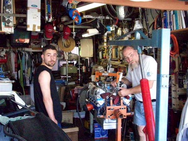
Almost ready....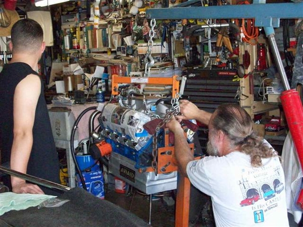
It's gotta fit in here....
Not impressed with lack of progress...he'll be moving shortly!
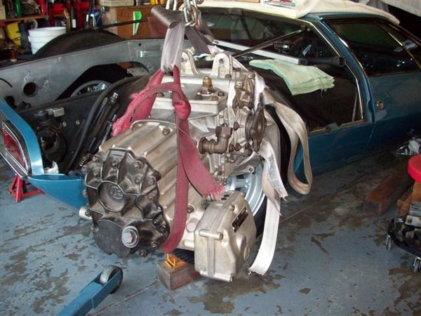
I lost my photographer when we were actually lifting and lowering.....
But here we are unable to go any lower...and had to start taking things off..... Oil filter was first thing to go...then this pesky sending unit!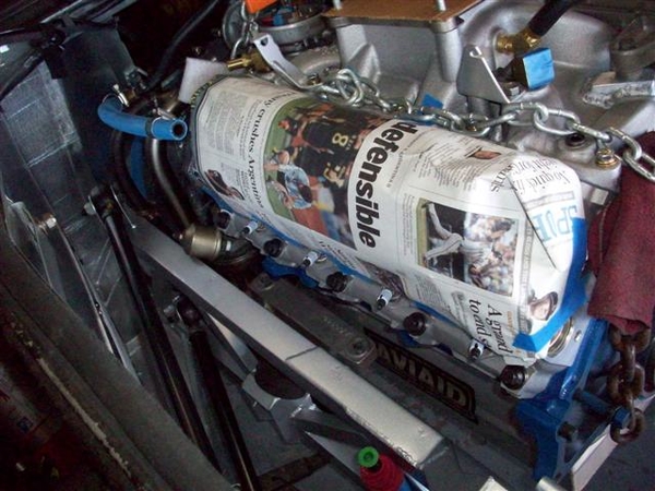
I did find a solution I believe. Will use something similar to what was used in the 1969 Boss 302's with power steering. They used a fitting in the block connected to a remote mounted bracket/fitting(front of the head! Imagine that!) for the sender, with a short flexible line! It will work beautifully!
RH side....no problems! NOTE IN THIS PIC Y0U CAN CLEARLY SEE THAT i HAVE FORGOTTEN TO PUT THE ONE PIECE REAR CRANK SEAL IN PLACE!!! THAT GAP IS HUGE!!! This will come to light once the engine is fired up for the very first time!!!!
 ![]()
![]()
![]()
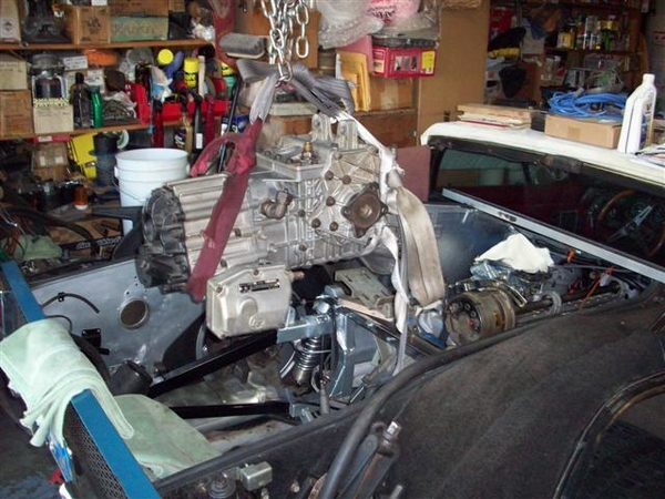
Almost there...checking to see that we don't need to take anything more apart! Removed my new fuel line about this time.... Using the leveler we nosed the engine down to clear the front of the jackshaft bracket, and then once that was in place, raised it up and maneuvered it into position above the mounts.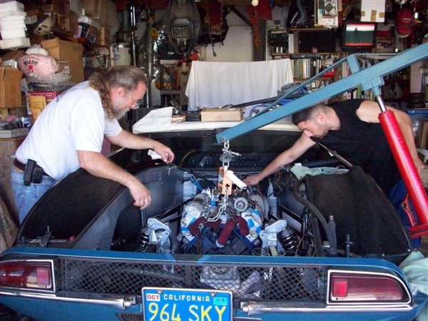
Note how the hoist angle is. From the side, not perpendicular, but just a tad to the rear. The rear tires are on the car, and they are sitting on 2x4's to get it off the ground so that the hoist wheels clear the pan etc. If we needed more "in" I would have removed the wheel and left the chassis up on jackstands, but you'd need to strategically locate the stands so they didn't get hit by the hoist legs!
I was able to climb into the engine bay and sneak the engine mount bolts into position from the rear, by looking down from above to see if we were close to the bosses in the block, and then just push and shove a bit (OK, cheated and used a mirror once...) to get the bolts started and then cinched them up snug, but not a final tight yet! I may raise the engine back up if I can by putting spacers between the mounts and the block....time will tell!
It felt REALLY good to drop the weight of the engine down onto that chassis! That was a lot of load off of my engine stand and my brain! Finally!!!
And that's how we got to the picture at the top!
Steve
Attachments
Images (8)


Try these for header bolts. They are tightended with a 5/16 hex wrench, very tiny.
Coleman header bolts
Looks great.
Jay
Coleman header bolts
Looks great.
Jay
Stage 8 has a similar setup but utilizes vary types of locking devices to prevent the bolts from backing off.
Steve FWIW my car has allen head machine screws to hold the exhaust manifold except for 3 that are regular bolts.
Also here is pic of (dirty) oil press sender.
Ps your mileage may vary, I know motor had been pulled on this car.
Also here is pic of (dirty) oil press sender.
Ps your mileage may vary, I know motor had been pulled on this car.
Attachments
Images (1)

Denis,
Thanks for the shot!
Yours appears to be a modified original, just like my other one....and a few others that I found shots of in my collection!
Yours is simple.....as you have no fuel pump!!!!
It gets pretty tight in there with the fuel pump and the sender, and the oil filter..... If you need to change a fuel pump, I'm guessing that you remove the oil filter, remove the oil sender, then the fuel pump......
I'm going to see about using the remote mount system ala Boss 302.....it will be mo' better if it all fits!
Ciao!
Steve
Engine install plus one day:
OK, bent, unbent, bent, almost kinked..bent, rebent, formed, deformed and finally installed my hardline from the fuel pump to the top of the engine! I think I now have about 1/8" of clearance between the frame brace and the line.... I didn't have a bender that would do tighter curves that I would have liked to have had!!! I used a variety of bits and pieces in a vice and managed to get the lower bend a bit tighter and also took out a 3/4" or so piece from the original flare to suck it in closer to the pump..... Shoulda known...!
Straightened the bent lower lip of my block plate (aren't yours bent too???) set it in place on the back of the block, and lifted the flywheel in place. Engine needs to be tipped forward just a tad even for the block plate to fit! As it gets heavier...it will want to sit down to the rear.....and hit parts on the fresh paint on the frame!!!
ARP bolts want 80ft-lbs of tight when lubed with 30W oil.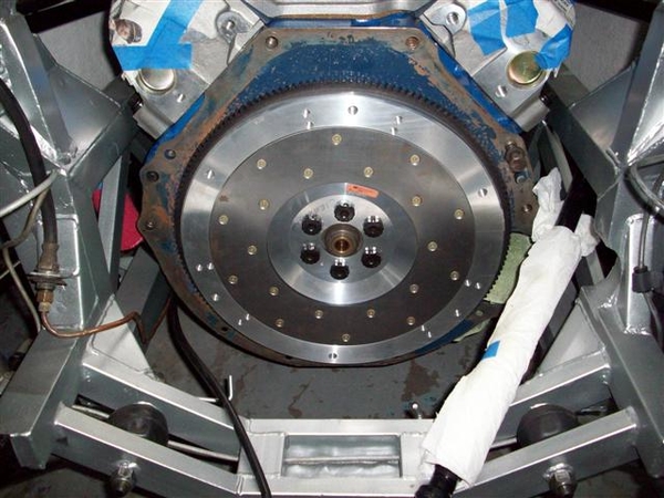
Tapped the pilot bushing carrier in first...so that I didn't bugger up the flywheel with an errant hammer blow! Used a socket to drive it home...once it hit the end of the hole, the entire hammer operation sounded completely different! Much more solid when seated!!!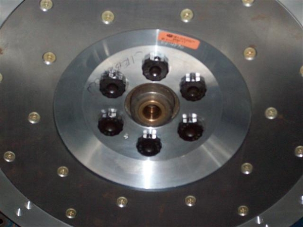
Clutch disc in place with an installing tool: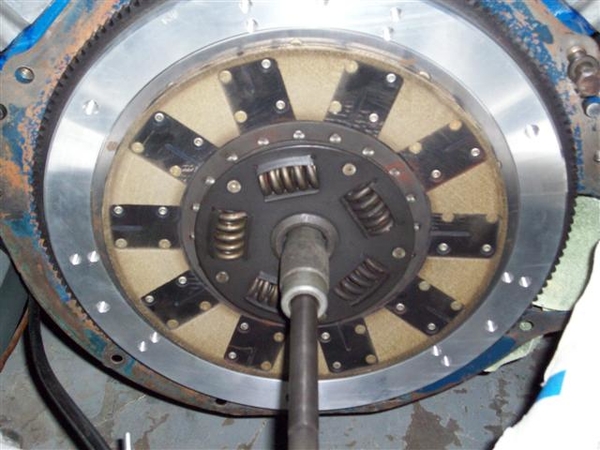
The disc is a Kevlar construction friction surface on both sides. I am VERY happy with the feel!!! No grabbing! Very smooth engagement. This has just under 20K on it IIRC...can't find my mileage log at the moment!!
Carefully slip the pressure plate (stock Ford unit) in place and bolt it down! Again ARP bolts...no spec, so used Ford spec of 20ft-lbs. Hope that isn't too much for aluminum!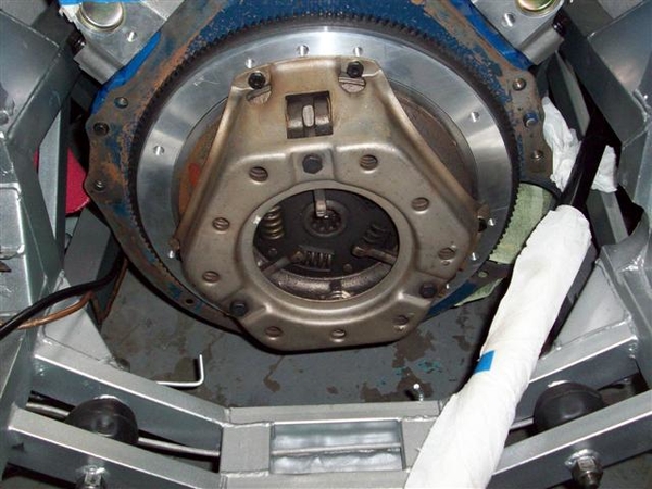
In this shot you can just make out the gap between the center splined hub area and the machined pilot bearing area. No clearance here would be a bad thing. It would mean that your flywheel and or friction disc has worn so much that they are touching...not a good thing!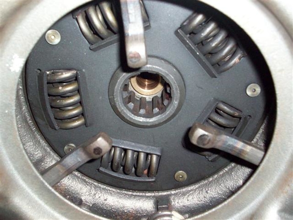
Using the ol' eagle's eye, you can check the work of the clutch disc installation tool before you cinch the pressure plate bolts down all the way! Make sure that disc is centered, or your ZF will not slide into place.....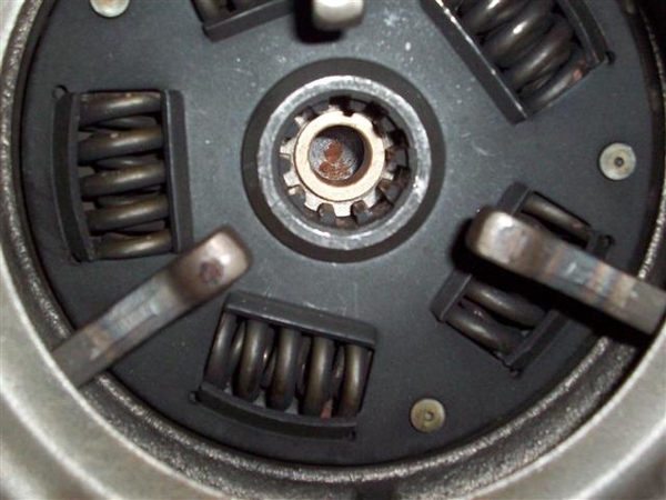
Time for the bellhousing to go back in! This is tricky....to get it in place without banging up the paint! How the heck the factory put these engines in, as an assembled unit, is beyond me....they must have had a hole in the floor that the front of the engine went into and was then lifted up........ Let's just say that it is a tight fit!!!!
At this point, with the bellhousing installed, the rear ladder bar MUST go back in place. (I guess you could wait until you put the ZF back in, but it will be one helluvalot heavier lift once you do!!!) You lift up on the bellhousing and rock the engine forward (watch out for the distributor cap if in place!!!!) and then slide the ladder bar in place on the left and then feed it thru to the right. I should mention that the frame is now supported by a jack under the rear crossmember, just enough to take the tension off of the shocks so that the upper bolts can be removed....
I was able to slip the two bolts in on the RH side, capturing the shock top as well! Here is what I saw on the LH side....but it was expected!
I raised the car up enough to put another 2x4 under the RH wheel to put some tension on that side of the frame and lowered it back down. The LH side was still on the jackstand. It helped!
With the help of a ratcheting tie-down, I was able to pull the remaining little bit back into place.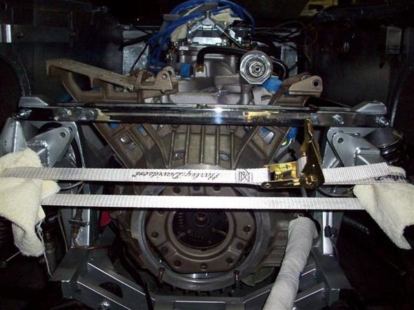
Using my knees and thighs to gently push up on the LH wheel, and lifting the bellhousing with my hands, a third hand pushed the bolt home the last half inch with a firm push from the handle of a hammer. (No hammering on the new parts....yet!)
Being the problem child that she is, the car gave up one last issue....the new center bolt on the LH side would not go in from the front to the rear....so went in rear to front....AND may need to be shortened for clearance with the AC arm on the bellhousing. Here the engine is just resting on this bolt....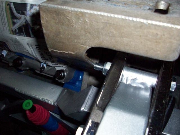
We can make bolts shorter....it's making them longer that's tough!
I connected a few hoses and easy electrical connections....and called it. More tomorrow!
Ciao!
Steve
Attachments
Images (9)


Steve, I installed all those bolts Front to back (nut on rear). The bolts heads on the ones I removed had been ground to clear the torsion bar.
Next step requires TOOOONNNS of patience,and small fingers, installing the trans to the bell housing. Make sure your 'T' head bolts are in good shape and lined-up correctly so as not to interfere with the ring gear. I ended-up replacing 2 of them. Thank God LLoyd had them in stock.
Denis
Next step requires TOOOONNNS of patience,and small fingers, installing the trans to the bell housing. Make sure your 'T' head bolts are in good shape and lined-up correctly so as not to interfere with the ring gear. I ended-up replacing 2 of them. Thank God LLoyd had them in stock.
Denis
Denis,
I think you mean pressure plate...the ring gear is up against the block.
"Shouldn't"....be any problems as this is the same pressure plate that came out....but alas, IS a different flywheel, so we'll see!
I'll take a peek in there tonight and double check! Thanks!!!
Steve
I think you mean pressure plate...the ring gear is up against the block.
"Shouldn't"....be any problems as this is the same pressure plate that came out....but alas, IS a different flywheel, so we'll see!
I'll take a peek in there tonight and double check! Thanks!!!
Steve
correction^: pressure plate.
***the 4 bolts you have already placed are special 'T' headed. Maybe if they were glued in place, As you slip the trans in place and try to line-up the shaft, bolts will get bumped will require reseting, so you will have to visually inpects all the bolts to ensure they are properly seated.
Unless your AC condenser has been taken-out!!!.
Still ensure alignment.
Denis
Tuesday eve....
Installed gas line to fuel pump, from tank. Not terribly easy being upside down and cramped....but it fit.
Broke a tooth during dinner.... roasted chicken and salad....what's up with that! Off to the dentist for another damned crown tomorrow....I hate this "old" thing.....!
Spent a good while bending up the old 1/2" steel tube that fed vacuum from the rear of the manifold to the steel pipe on the side of the frame rail. Could have run hose from the pipe to a fitting....but that would be too easy....
Decided to check my rear jackshaft pulley alignment....went back to the storage shed and pulled out the alternator and adjuster....
All looked well except that I did need to reuse the tiny .110" spacer that I had made up previously! At least that dimension didn't change...I had to trim a pinch off of the key end, but not a big deal.
What did change, is the position of the jackshaft pulley, which now causes the belt to rub against the large pivot bolt at the bottom of the alt. No matter which way I go through, front to back or back to front.....it rubs...
I decided to try the middle position for mounting the alternator. It has always been mounted on the outside position as long as I have had the car, and the wires do not seem long enough to fit to the alternator!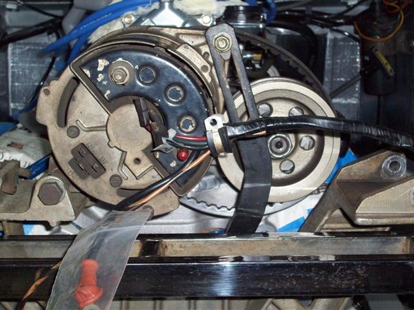
I was able to install the new alternator adjuster bracket that I bought on the way to Reno this year! It actually fits! However, if you note in the picture above , the wires do not fit....they are original ends...and don't look to have been shortened anywhere...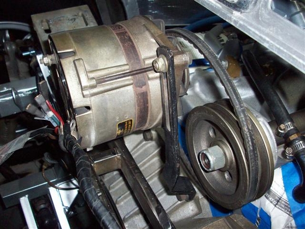
I'm going to go through my pictures of other cars and see if perhaps the rear of the alternator can be clocked slightly different 120 or 240 degrees...to make the connections closer. Just seems like the wires would be sorta taught, hanging out in the air.....
Probably should put a new bearing or two in the alternator as well...check the brushes too....another day!
Ciao!
Steve
Attachments
Images (2)


Wednesday....
Sort of an "investigation day"...no real progress....
I forgot to note that yesterday I noticed that the lower rubber hose from the Y-pipe to the frame pipe will be too long now due to the motor drop..... Not going to worry about that until the trans is in place and the attitude of the entire drivetrain is in it's place...
This will be the theme for a few things, notably the exhaust system too!
Played with checking header fitment...
This is RH header from Set#1. An early Hall Big Bore is my guess. Very thick flange at the head, not so thick at the collector. Finished with an 80's sort of alumicoat....nasty crap...no way to keep it clean like the new ceramics!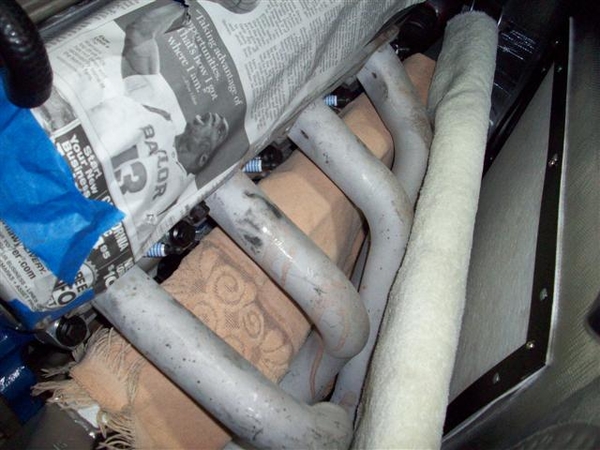
Fit on RH side is actually pretty good. I want to see if I can either adapt easily, or construct a new set of the heat shields that were on the original headers....we'll see!
View at the collector. Good location.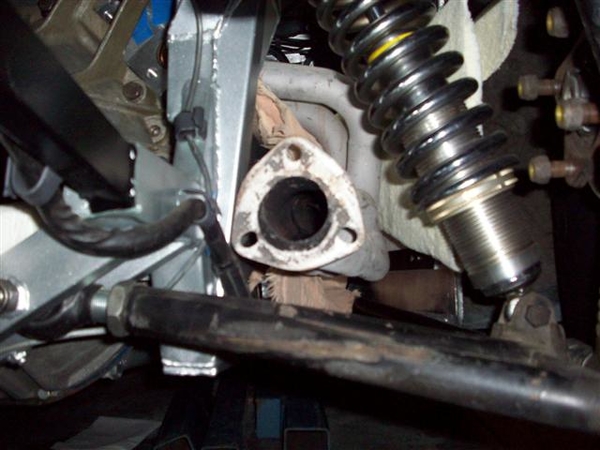
Picture from way back....lots of clearance for the a-arms. I like that!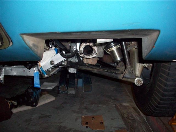
I made a "gauge" of sorts...to help compare set#1 to set#2 for location..ie are they directly interchangeable? Stay tuned...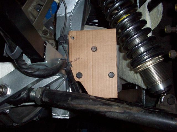
Set#2 RH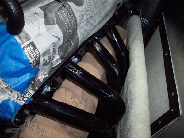
Flange view. A little lower and closer to the frame.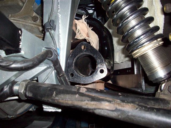
View from way back.
View of template mounted on #2. Note that the other pattern is #1.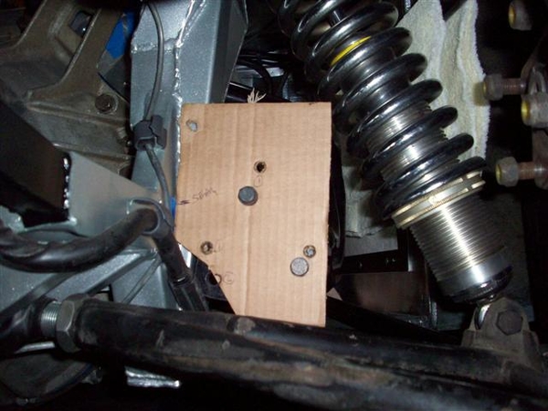
SO answer to the above question, will the headers interchange with the mufflers welded up??? HELL NO! What was I thinking.....how silly!
On to set#1 LH side....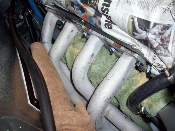
This one has evidence of contact with the upper bar of the 4-link suspension...and is very close to the frame rail too! I will probably attack this with a piece of round stock and a hammer to give a little more clearance...cutting and rewelding the pipes is a messy option....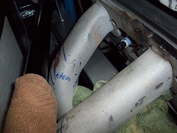
Here is a way back shot of the collector.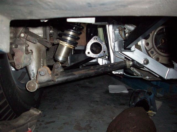
Again, will check this all out once I get the ZF back in place... It is a lot of weight to not have in the car to fit all of this....
Today was like Christmas! FINALLY opened the box that Dana of Mangusta Int'l sent me back when I started this project almost a year and a half ago..... What's in this box you ask? A brand new pair of ANSA muffler copies, in stainless!!! And boy are they a set of mufflers!!!! The pictures don't do them justice...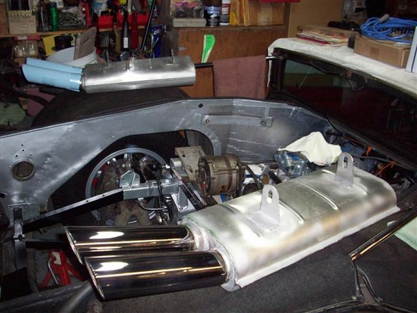
Mounted one up just to see....but I have some concerns about my hangers and if I have them on the correct side etc. Will see what sort of feedback Dana gives me....!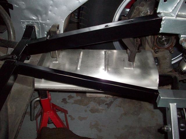
I don't know if my hangers are in the stock location, and I am not 100% sure what side of the hanger the muffler should be attached....
So, that's it for today. Still don't understand what's up with that stupid alternator mounting system...or what I will do about it. Now is when I wish I had some original pictures of the car!!!!! ...way back before people started dorking around with it!!!!
Ciao!
Steve
Attachments
Images (13)


Thursday:.....I don't remember...that was a long time ago on this project....! ![]()
Friday: Couldn't avoid it....time to install the ZF!!! Something else that is hard to avoid....scratching up the paint trying to get a ZF into the back of a Mangusta! I will need to spend a little time with the teeny brush and some paint...........ugh! It was tough, but then I was the lone ranger on this one...no extra hands or eyeballs...
I didn't take any pictures pulling the ZF out...and couldn't remember exactly how I did it....sheesh this project is taking a long time!!! Again used seat belts....tipped the engine up as far as it would go (remove headers for more clearance!!!!)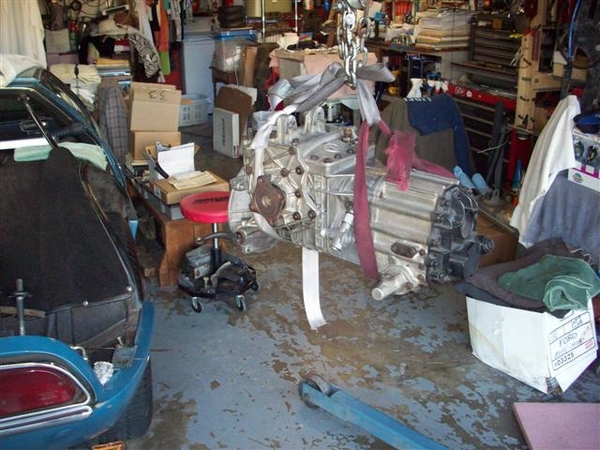
Tried to go in from the side again, like we did with the engine but in the end, going straight in from the rear worked out best.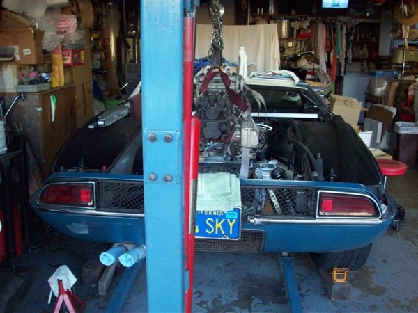
Just a tad nose up allows you to drop it in place, nose facing the left AC mount, and then rotate it clockwise into position while lowering...trying not to get tangled up in the LH steel brake line, or the frame, or the ladder bar, or the AC condensor, or the rear valance...... Setting it close to the lower two mounting holes, HEAVY towel on the crossmember...tip the nose of the input shaft into position and then jack and lift and push....and voila!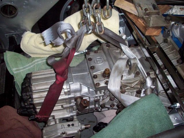
It should be noted that if your clutch disc isn't lined up properly...it will not be half as easy....as this was.....!!! I got real lucky, splines lined up and she slid right into place. Threw on the retaining nuts and dinked around with the rear mount for the rest of the night.
Saturday: worked on rear ZF mount. Needed bolts so took a trip to Orchard Supply for good grade 5 stuff....ended up with some overkill grade 8's for the center two bolts, because they had more "step" on them, and also got some 3" 3/8" bolts to use on the end two mounts, along with my unpatented frame stiffener modification. (Which I forgot to take a picture of...but I think I posted way back in the early pages of this adventure!)
A pair of stainess steel O2 sensor bungs and plugs showed up in the mail! Figured since I was welding...may as well put a pair of these in the tail pipes just after the header flange.... Could aid in tune up and performance tuning on the chassis dyno!
Installed the half-shaft assys. NOTE: with your wheels hanging suspended (frame on jackstands) do not be alarm if all of a sudden your wheels seem to bind at 180 degree intervals.... What is happening, is that your half shaft ends are binding against the ends of the u-joints. One side does it on this car, the other doesn't...go figure..... Once you put the car back down, you will not have this problem....or at least you shouldn't!
Once the half shafts were firmly in place, I installed the clutch slave cylinder, but of course had to take it back out because I couldn't get enough adjustment out of the rod, because some of the threads got buggered up...pulled the rod out, chased the threads with a tap, greased it all up again, and put it all back in place!
Installed the roll pin back into the shifter shaft, and installed the ground strap to the rear of the ZF trans and to the frame.
Started trying to fit hoses and figured out that when I got the last two hoses to try (for connecting the bottom of the Y-pipe to the frame pipe) that I didn't have my glasses along....so ended up with 1.5" hoses instead of 1-3/8"!!!!
Sunday sunday sunday!!! Sorry...drag races are happening up at Sears Point....couldn't resist!
Played with hoses today! I hit the Kragens with my old hoses to return, and my old hoses from the car...my glasses, 6" steel rule, and a tape measure for anything over 6"....
Found a Gates #22185 hose of the proper 1-3/8" diameter! I was able to get two hoses that will do the job...give me a spare to carry in the tool box... for only $8! The hoses I was returning ran $17-20!!!
I cut this apart, with the RH section as you see in the picture being my primary piece, and the LH section as my spare, but I found an errant slice in the area near where the clamp would go, under the label....so I wouldn't want to chance that.....of course once I cut the hose up I ruined my option of returning it...but for $8 I'll order another and be real fine with it! Hang it in the rafters!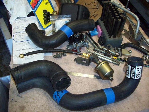
My old lower hose is at the top of the picture....and can also serve as a spare for this too! I'm surprised at the difference in length of new to old...but then EVERYTHING but the actual Y-pipe and the under frame tube is different....gotta keep telling myself this...! Installed the "uncut" piece in the car...one hose to go! (Ordered another potential for the water pump hose.....but the flex hose I have may work in a pinch.....read that as "requires trimming prior to installation.....")
Something else to note in the picture above...my solution for relocating the oil sender unit! This piece is donated from a Boss 302 parts book. Cars with power steering and a Boss 302 needed more room in the area....so this was the solution. Mounted it up with a 5/16" bolt to the front of the head and it came out nicely! Cost me a Ben Franklin to do it....but all I had to do was pick up the phone to National Parts Depot (Mustang parts+++) and it magically appeared at my front step two days later, already put together..... (I tried looking for the fittings to do this....but gave up....I wanted to finish the car, not manufacture everything needed....)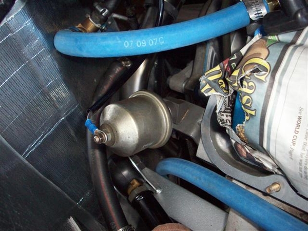
It will clear the valve cover just fine, and everything else...... Nice clean installation that perhaps others of you could use as well!
Here's why....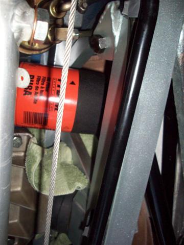
You cannot see the oil line in this picture, but with the fuel pump, the oil sender extension AND the oil filter all in there....it's tight! This car had an oil filter remotely mounted.....so I never had problems previously! But since the threads in the remote adapter weren't threaded deep enough for this engine insert, I have left it out for now and will change filters with the large mess that everyone else has......!!!!!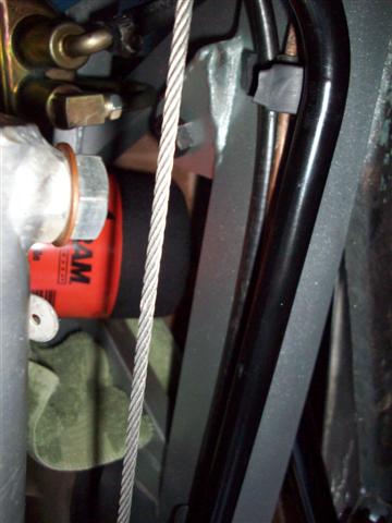
As a result of the remote filter...I never was aware of how tight things are there...including even getting the oil filter up near the engine! The filter would not physically fit between the oil pan and the frame rail, until I unclipped the vacuum hard line from the rail and moved it just out of the way, as you can just make out in the second picture above.
Took care of a few things on my "Don't Forget List"!!! Tightened lower shock bolts, motor mount bolts (to engine), and the top clamp on the vacuum hose to my bent up steel line. Still have a few things to do, but that's OK as long as I have them written down!
Installed some heat shield to the back of the firewall door to replace that garpy crap that DeTomaso used for water collection....I mean insulation.....
Dug out my sway bar and set that in place. Due to all the bolt length and orientation changes due to the attempt at a simple frame stiffener, I will need a spacer between the frame and the sway bar clamp to raise the bar to clear. I checked this out before, and I think 1/2" will work, but will check again and see if I can get away with 3/8"! That is where I left off this evening.....looking for suitable scraps of material or a willing donor!!! None found yet...but it's gotta be around here somewhere....!!!
Ciao!
Steve
Attachments
Images (9)


The march continues.... (from two days ago..no work last night or tonight due to grandkids at the house, and a mystery clutch malfunction in the 68 Cougar (son's car now..) plus taking the wife out to dinner and a street dance sorta thing...pay the dues....!)
Called about header coatings, Caps of Fresno appears to have a high temp (1700 degrees) version that uses titanium...or that's what they call it.... instead of aluminum, which melts at 1300 degrees and can then separate....so for no additional cost, they can do the higher temp job! With blasting the old electrostatic coating off of the headers I want to use, they can still turn around the job in 7-10 days! Great!!! More later..
I worked on the sway bar spacers next...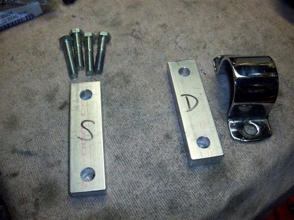
These are cut from the same 1/2" x 1" bar stock that I made my prototype chassis stiffener bar from.... Cut to length and drilled with 3/8" holes. I have not yet beautified the rough edges on the ends....
I also ordered some smaller diameter headed 12 point 1-1/4" long bolts....as trying to use the full headed bolts causes the side of a socket to contact the ladder bar and may or may not fit down onto the bolt! I have seen many a socket head (allen head) bolt used just for this reason! These things look like 12 point header bolts....for lack of a better description. Will post a pic once I get them....more special order from Fastenal! I also ordered a 5" long button head bolt to try was an alternator pivot bolt to perhaps help with my belt interference issue.....
Back to sway bar spacers....
Installed left and right....I gotta be getting close...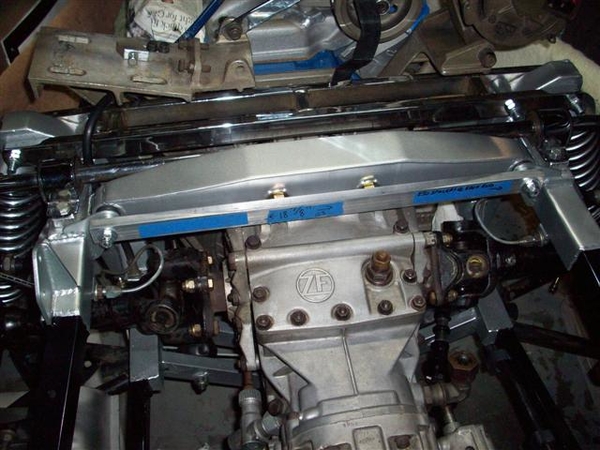
Close up: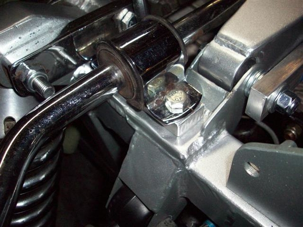
Last thing I did the other night was to get down my original air cleaner and check the fit! That was the goal of all of this work after all!
Well, it looks real good....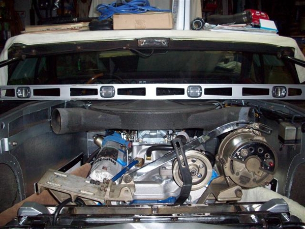
But success is fleeting and not to be found here..... The air tube horns are about 1/2 proud on either side, and the center of the air cleaner would just contact the shield by 1/8-1/4", if you are to believe that they would be flat... I used a level here to simulate flat....of the closed covers....
The carb stud also is proud by about 1/2 inch, but I could effectively deal with that in a creative sort of manner if I had to...
The long ending to this story will be to go back to my Performer intake with a shorter carb mounting pad.... I have the manifold but it needs the ports enlarged, and the rear mount piece welded onto it... Installation is something that I don't see as being too large a deal now that I have been through everything else!!! But for now, we run the Performer and I dig out my old low profile air cleaner to get out of the garage and down the road a few miles!
The lower carb height will probably cause me to use a manual choke setup....which after looking at this...is probably what I will need to do with the Performer RPM intake that I have installed presently. Just too much stuff over near that pesky center bearing area of the shaft bracket!
....I thought my measurements were more foolproof....so much for RevA!!!
Gonna go post some header pic's in a new post!
Ciao!
Steve
Attachments
Images (5)


Looking good "Father Goose", you are almost there!
Dennis,
Almost is a very BIG word when working on these cars......I "almost" get my list all crossed off only to find a crapload of other little tiny bits that confound my ability to move forward in large increments!!! We're down to baby steps....very small baby steps.....
Progress? I'll let you be the judge....
Ordered a belt for the main jackshaft drive...that I thought was between a 13A1220 and a 13A1230 (metric sizes...) only to get a belt from Good year that had a unique number....only to find that they sent me a 13A1220..... I wanted a 13A1225.....but apparently when belt makers no longer want to sell something, they take the old number....and assign the next closest belt size to it.......and don't tell people that they are getting shorted! Get it....shorted....OK bad belt joke.... Grrrr!!!
Ordered and received some muffler hangers....rumor was that they were the same as some Alfa Romeos, which ARE the same as Pantera hangers.... Well, they are NOT an interchange for Mangustas...... They would only have worked in the rear most position, but the center to center distance of the holes is about a half inch greater...which hangs the muffler down too low in the rear..... Grrrr!
Now I need to find a source of 1" (24mm) thick material from which to cut hangers from .....as my old ones were 3/4" material which has distorted the frame hangers...and is cracking to boot..... hint hint, nudge nudge!!!
Worked on reforming my headers ever so slightly to clear A) my frame and B) the upper left control arm....on the left side front one or two pipes.... Got the top done OK, but in working on the underside of the front most pipe, I managed to split the weld.....so had to file off the aluminum coating on the header and weld it back up.... No biggie, as they will get coated all fancy and such next week.
OH, and I can't take any pictures with my camera as my son dropped it dead smack on the lens while he was taking pictures of his car....that we were chasing a clutch mystery in..... New pressure plate (3-finger!) fixed it...but we could find nothing wrong with the old one!!!!
One bit of progress, was that I did weld on studs to allow me to add some exhaust shields similar to the OEM ones....after I find some .041" aluminum sheet, fabricate some bucks to pound it out on.....and some time to do it all.....ugh!
I received my exhaust header studs in the mail yesterday, and they appear to fit...can actually get the headers on the car with them all in place!!! Not so sure about all the nuts......on and off while up against the head....but we can deal with that on a case by case basis.......!!!
Lots of other stuff to keep me busy....I hopefully will get to the front hose splices today, at the tubes, and the radiator....replace them with Gates Green Stripe. Less rubber hose to worry about!!!!
I can install all of the exhaust studs...plenty of anti-seize for the future....!
Carb is bolted down, and my old air cleaner assy fits fine.....just not the DeTomaso version! Argh! Need to find a hot wire to connect the choke lead too....
And my list goes on with little stuff like this..... I guess these are just time fillers....they don't really need to be done now, but since the cooling system is empty....
Ciao! Will post more pic's once I find the wife's camera....and promise not to destroy it!!!
Steve
quote:add some exhaust shields similar to the OEM ones....after I find some .041" aluminum sheet
Steve,
Use stainless for the heat shields.
John
John,
Not sure how stainless would respond to forming it over a wooded buck....I know aluminum can be formed by throwing old chewing gum at it....
Well, still haven't worked out the camera thing yet...but did manage to get mine to work, as long as I don't try to zoom....!
Shipped off the headers after I finished some final filing down of the welds.
Installed the exhaust studs with plenty of anti-sieze. The headers actually install with them in place! What a concept.....
Installed a couple of the valve cover studs....still have newspaper covering the rockers until I get done dorking around in there...don't want to drop stuff and dog hair into the new internals....! Will do the last 6 when I am ready to install valve covers!
Installed the main jackshaft drive belt and snugged down the adjuster pulley. As I posted in the Tech Section, I am not happy with the fit, as the adjuster is all the way out at the end of it's travel....but what I thought was a slightly shorter belt that I ordered, turned out to be the same as I had already tried....ugh.
Tightened up the motor mount to frame nuts. Lifted engine just a hair to take pressure off so that they could seek "at rest" and not be distorted from my moving things around whilst installing the trans.
Replaced 3 of the 4 front radiator tube splices with Gates Green Stripe 1-3/8" hose. The top left connection at the radiator actually has a bend in it that will appear to kink the straight Green Stripe. Current hose is still supple, so tightened the hose clamps and left it.....hopefully that small piece will NOT come back and haunt me somewhere....near Barstow....
I don't think Green Stripe hose comes with curves.....but something with about a 135 degree angle in it would probably work...not a tight 90.
Tomorrow (later today!) I hope to pick up a candidate for the final hose, from water pump to lower tube, a different tiny heater hose for the water pump connection, some fasteners for the sway bar and alternator, and some misc lock & flat washers, and try and dig up some flange gaskets for the exhaust while I'm at the AP store!
Time to consolidate my notes to a new list. Too many scribbles and misc notes....gets confusing, plus I ran out of room for new notes to help my aged brain keep up to the program here!
I'm tempted to install my other set of headers just to fire this thing up! Connect some straight pipes.....OK...back to work....enuf of this!
Getting close to "just waiting" until the headers come back!.......nah!!! Plenty to do!
Ciao!
Steve
Wednesday the 28th.....
Time for some pictures!
Last week got detoured a couple of days working on a clutch job....
Those aren't DeTomaso parts!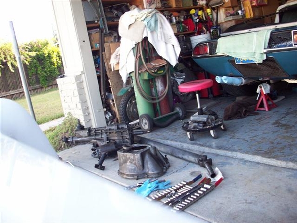
Son's car came up with a lame clutch pressure plate...same type as used in the Goose! Couldn't find anything in terms of a smoking gun as to what failed....aargh! A new pressure plate seems to have solved the problem...but also fixed some minor naggy issues, like bending the equalizer bar to clear the shorty headers, and welded up some things that were starting to show their age!!! (and bad gas welding skills of the author....I love my MIG welder...!)
Found these exhaust flange gaskets which seem to be a perfect match to the flanges that I got with the new mufflers from Mangusta Int'l, which fit my old Hall headers. I may need to enlarge the holes to fit the pattern, but there is plenty of meat to allow this. There is a raised sealing portion and it is metal jacketed on both sides, so no messy "header" type gasket battles! About $4 each. Sorry for the crummy picture...camera just isn't what it used to be...!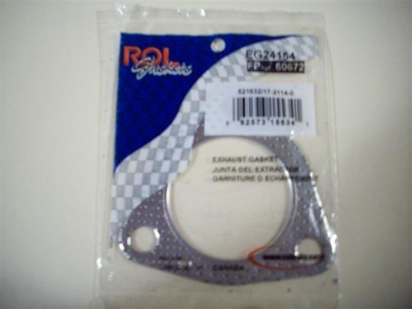
Traded in my little heater hose that goes from the water pump outlet to the hose on the firewall. Fits very nicely! About $7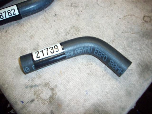
Installed!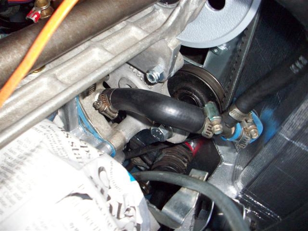
Received my new lower hose which connects the water pump to the lower chassis tube. Cost $20.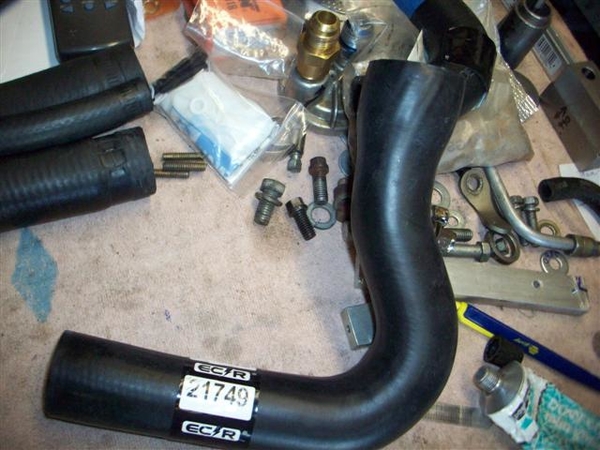
Needed to do just a tad of trimming to get things to line up and not bind.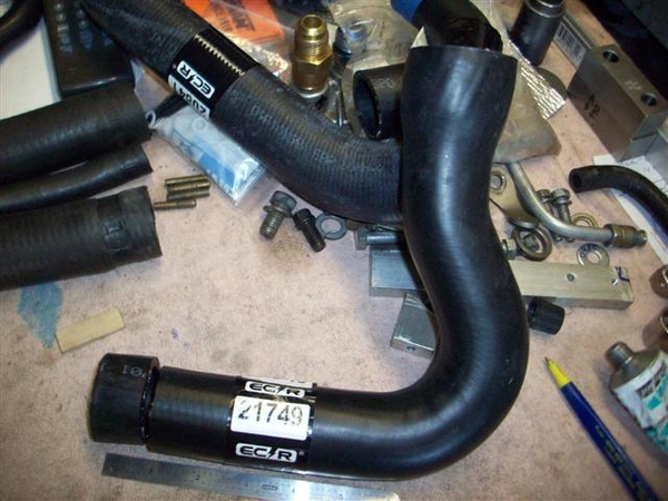
I took one inch off of the lower end. It should be noted that this hose is 1-3/4" at the top and 1-3/8" at the bottom, just what doctor DeTomaso ordered!!!! (last hose was 1.5" at the bottom and required lots of hose clamp tightening!
Tools that made the job MUCH easier!!! You physically cannot get into some of these areas to tighten up hose clamps....but these little buggers saved the day!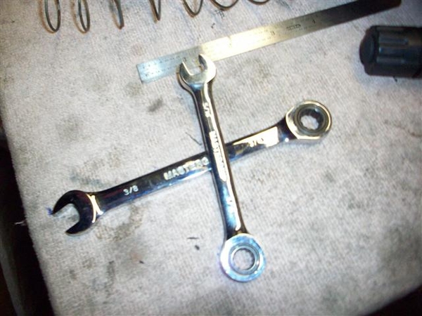
Here is a shot of one area where the screwdriver just wouldn't cooperate!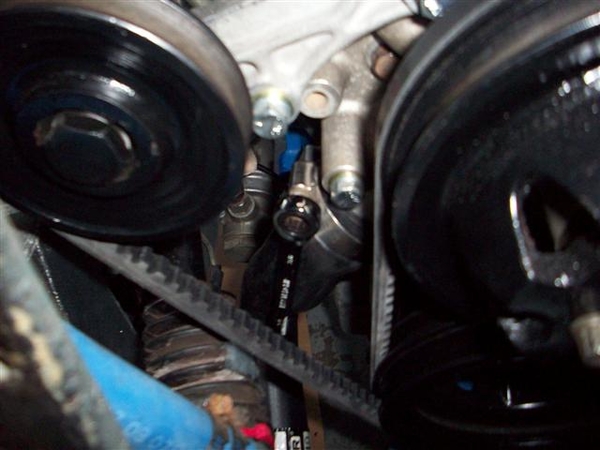
I won these at one of the PCNC Christmas party raffles and I am beginning to like them a lot! I had a version of Craftsman wrenches, but the gear teeth were "more coarse" where these have more teeth and offer more ratcheting for less movement! (Finer the teeth, the more work gets done in tight places!)
Glued the valve cover gaskets to the valve covers, installed the V/C studs into the heads and started working on the coolant overflow tank....which is where things went awry last night!
I was mistakenly thinking that "all I needed to do" to complete the cooling system was to slap the overflow tank in the bracket and connect two hoses....Not to be! The clamp which is supposed to secure the tank to the firewall bracket, is about 1/4" to long on each side. I had wrapped the tank in some 1/16-1/8" thick foam tape, but it was not enuf..... SO, gonna scrounge up some thin tin and make myself a new one!!! Seems to be the only option.... OR do like the PO did, and wrap it with VERY thick foam tape....which was super ugly.... I'll use tie-wraps before I do that....!
Spent tonight doing PCNC bookkeeping in prep for meeting tomorrow night. Will try and order up some material for exhaust hangers yet before I hit the rack...internet never closes!!! ![]()
Steve
Attachments
Images (9)


Steve I see that you have mounted a Fram PH8A oil filter. I used a PH8A on my Italia with a Ford 351 Windsor and noticed that my oil pressure dropped from 58 pSI to 46PSI hot at 3000RPM. I thought my engine was giving up but on a hunch researched the Fram and found they are of very inferior construction. I purchased a NAPA gold which I saw on a display comparing the NAPA filter internals to the Fram internal construction.The presuure went right back up to the 58PSI hot at 3000RPM and has stayed there. Naturally I saved the fram filter and have contacted fram to tear it apart and verify what I think to be the problem which is the front of the filter has broken down and was pbypassing oil. Not a good situation.I will never use Fram again. Stick with the Ford FL1 or the NAPA gold. Jerry McGlothin Pantera 02222,Mangustas 8 MA822, 8MA542. Italia 0455,Vetta Ventura 0044 XKE 800483 ,XKE 32460
Jerry,
I am well aware of the filter issues with Fram. I believe however that as Jack DeRyke wrote, Fram was trying to cut costs and send manufacturing out of country, only to start experiencing problems, then brought works back to the US and the filter you see is a result of that. (Orange filter with black band)
Now, it could be a simple case of polish a turd, repaint a turd, same turd.....
This filter just happened to be one that I had on my shelf and will be a throw-away after I break in the engine. It only needs to work for as long as it takes to fire up the engine, wash all the moly lube off of stuff (which will tend to clog up the filter element....) take the sharp edges off of cast iron bits and pieces...and then it will be replaced with either the NAPA version or a Motorcraft filter, which is what I use as a norm on all the rest of our vehicles!
Thanks for the input! Always good to hear about sub-performing components!!!
Steve
Saturday,
In the "some progress is better than no progress dept"....
I found some 1/16" thick by 1.5" wide aluminum stripping at Orchard Supply Hardware (didn't have steel...![]() ) to fab up a new coolant tank strap. Came out very nice....we'll see how well it holds up!
) to fab up a new coolant tank strap. Came out very nice....we'll see how well it holds up!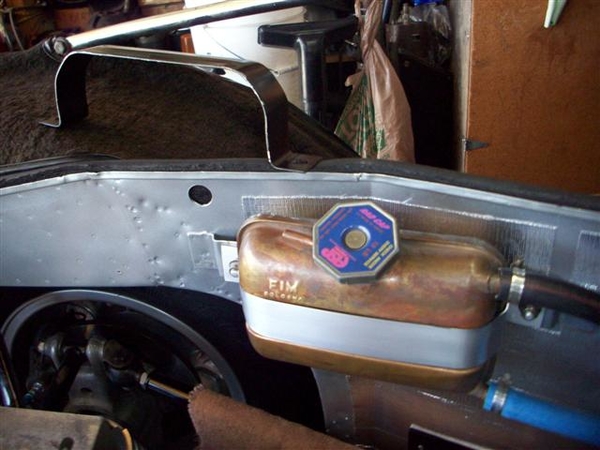
With this piece installed and hoses connected (excepting a hose from the tank to an overflow catch can....) I do believe that my cooling system is sealed and ready to receive liquid!!!!
In the "going nowhere fast dept"....
My alternator mounting and belt interference still continues to be a PITA!
I took possession of a new 4.5" long 3/8" "button head" bolt to try instead of the 10mm hex head bolt... While it appears to clear the belt now, the slightly smaller diameter of the fully threaded bolt, and the fact that my alternator spacer is about .025" shorter than it should be, allows the alternator to rock all over the place.....much more than it used to. I can fix this with a new spacer, or a .025" thick spacer for the spacer....more lathe time! Perhaps I'll shop it out to my dad.....
I also am going to try and get a real metric bolt and cut the head down on it. I think I can do an abbreviated button head treatment to it and perhaps win! Leave just enough hex on it for a socket or a wrench to grab it... I found the bolts in the Fastenal catalog, just need to order one...
In one last "you've got to be kidding" dept, to top this all off, I had installed my new ginchy valve covers (not yet revealed in photos) earlier in the day, thinking that all is well....can finally seal up the engine....WRONG! In order for me to remove this alternator bolt, I must remove the RH valve cover now! THAT was NOT a part of the plan.....valve covers may hit the scrap pile later....we'll see.....go back to a modified version of my initial idea....but not an emergency issue, nor is the alternator belt thing as I have options.... Put this crap on my "fix next winter" list....
Have a great day! I think I'm going to replace that fuel line from the tank to the pump. In thinking about it over the past few weeks, the stuff was starting to get hard from the additives in the fuel....and since I have no fuel in the tank, I have new fuel line, and the car is up on blocks....I may as well do it!
Steve
Attachments
Images (1)

Monday...
In the close but no cigar dept, a couple of things....
I think my exhaust hanger strap is too long...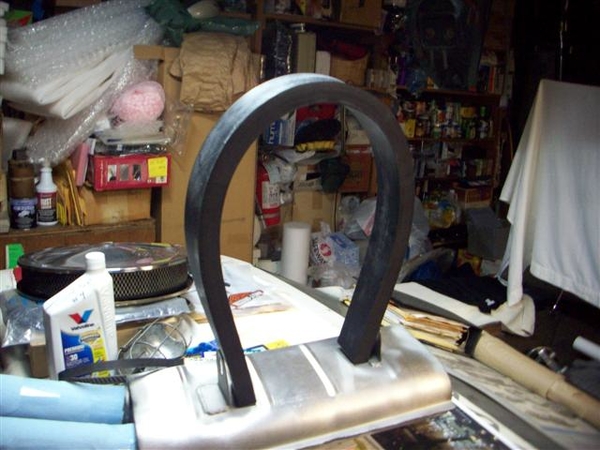
This is the 2" wide by 1" thick material I got from McMaster-Car. Will need to do some bandsaw work on it! Where's my bandsaw.....
These hanger reinforcements were "supposed" to be the correct part over the phone.....duh!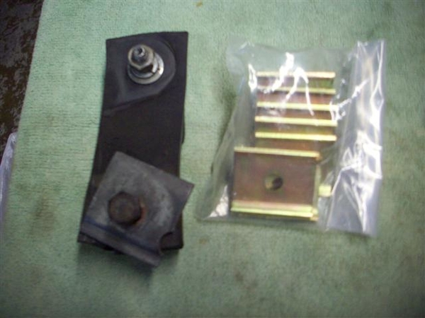
Turns out that it appears that the Panteras used the same reinforcement and also tubular spacer....but no one has piped up and said that the spacers were used on the Goose yet....Daryl?
8-31-10 update: Was looking through the Goose parts book, and found the hangers and reinforcements listed on page 52, two lengths of hangers specified from Fiat 1300/1800 models, and 16 of the little reinforcements and 8 steel sleeves as being sourced from the 1300 model Fiat!
Just waiting for headers!
I'm a little concerned about the radiator cap on the coolant tank...seems a little tall....but it doesn't appear to have been replaced either.....I do not want it to contact the shield and hose it all up!
Posting some jack pic's over in the "tool kit" thread.
Cheers!
Steve
Attachments
Images (2)


Whoo HOO!!!
Wife just called me at work and informed me that I have some freshly coated headers waiting for me on the front step!
I know what I am doing tonite!!!
....I'll try and remember to take some pic's....before I put them on....
OK, unpacked the newly coated headers and boy were they packed! Came to me in a Hooker header box! The 1700 degree finish is about as grey as the background of this text. It is not the bright and shiny aluminum looking finish that you see so often. I had heard that the 1300 degree coating can lift when in tight confines.....well, you cannot get much tighter than a Mangusta! Cost was no different....and I do NOT want to be in here again any time soon dorking around with headers!
Insert pictures here:
RH header: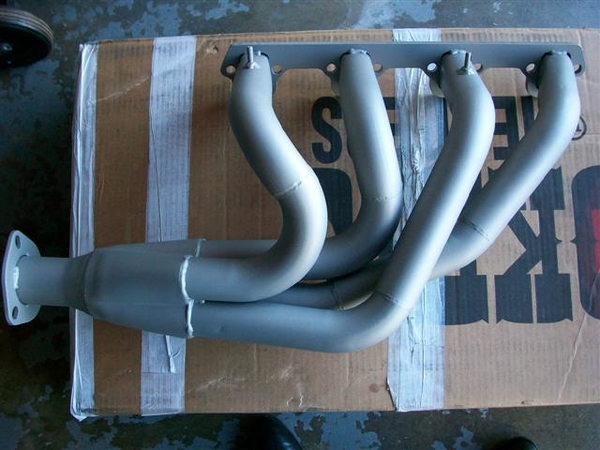
LH Header: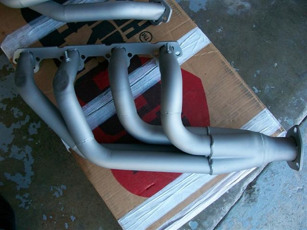
LH mods at front two pipes to clear upper control arm.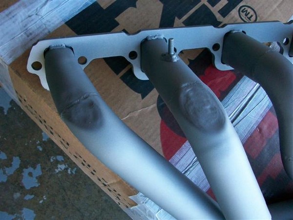
Underside of front tube on LH header to allow more clearance of frame rail!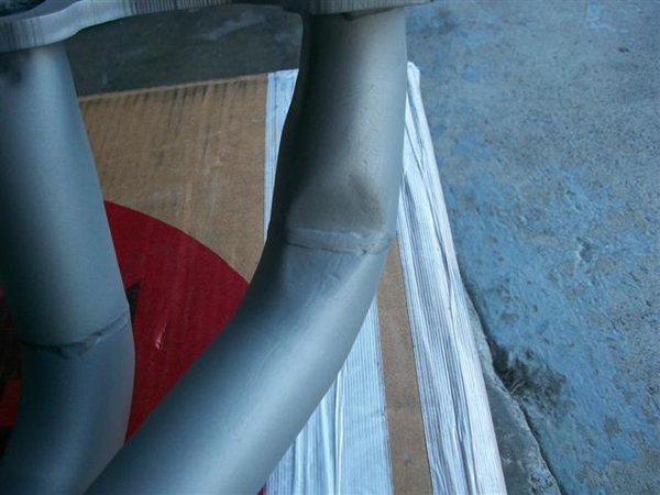
More misc: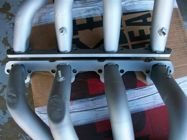
This is a deeper grey finish as I said above. Sorta grows on you! Is very resistant to staining and grubby finger prints!!! Pretty tough, but can be scratched....oops!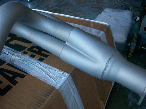
Of course since nothing can go smoothly, and why would this part of the job be any different....when I did the original fitting, I did not have my studs for the heads yet. Using aluminum heads, I figured I'd use studs to save the threads in the heads. I used a gasket and some short header bolts to see how the holes looked and removed material where it was in excess. (THESE ARE THE WORST FREAKING HEAD FLANGES THAT I HAVE EVER SEEN!!!! THE BUILDER MUST HAVE USED CRAYONS TO MAKE HIS PATTERNS.....) OK, that rant aside, these things REALLY suck....I mean how many times has Ford changed the small block exhaust pattern in 30 years? Correct answer would be: ZERO! NONE! NADA! I digress....
SO the headers didn't just slide on.....I filed and I ground with a carbide ball, and eventually they slipped right on like they were supposed to! This time, I dragged an old head out of the shed and used my extra 4 studs to test fit on the bench!!! Wasn't fool proof, but I was able to see better, areas that may be an issue...but still needed to trial fit the RH header about a dozen times before they cooperated!
I also ran into a couple of the studs that were tooooooo long. I could only get 1.75"or so studs, with 5/8" of coarse threads to go into the heads and I think a 1" fine threaded section to hold the headers on. I knew I may need to shorten some, but I wasn't going to get too anal and shorten them all..... (If I had my own metal lathe, my name would be asshole... ![]()
) SO, I had to shorten 2 or 3 on the RH side, and 1 on the LH side due to the angle that the tubes were welded in.....a cut off wheel, and a thread chasing file were all I needed to make this a very short job! I ran nuts onto the stud before I cut the bulk off, and that way, when removing the nuts, they chase the material back into position...clean up with the thread file and off ya go!
I also had to do some minor malletizing on the area adjacent to the studs so that the whippy dippy lock washer devices I picked up would fit, but in most cases it was due to being unable to get the 12pt reduced size nut in place. Conventional header bolts probably would have fit by a few hairs.... I eventually figured out that if I could get the nuts in place and finger snug, I could use the largest screwdriver that I owned, with a nice smooth flat blade, and slide it down between the nut and the header pipe. A few raps with the hammer and I moved the metal just enough for my small headed wrench to fit properly. Large headed wrench will probably be a no go..... (Some day I may look back and curse myself for all of this 12pt hardware and for being so anal....OK I kick my butt all the time for doing that already...nothing new!)
So, a couple of small scratches near the bolt/nuts on the tubes, but I'm not worried about that. Wouldn't be the first car I've seen with super nice finishes on their headers.....with all sorts of damage up by the bolts from sockets and what not!!! I plan on fab'ing up some stock type exhaust shields to "suggest" what the originals sort of looked like...which should hide these transgressions anyway! That is a later job....much later.....
I looked at my muffler to header fit, as I was thinking I would need a couple of 45's welded together to get an "S" shaped inlet pipe to the mufflers, but it looks now like the "kick over" will only be about the width of the pipe (1-7/8" OD pipe), so I think that just leaving it straight will be fine. We'll see once I get to fab'ing up hanger straps etc.
Oh, and the reinforcements and inserts arrived from Panteras by Wilkinson, and they look great! Just like my originals only shinier!
Gotta take the wife out for dinner tonite....to celebrate 26 years of slavery..I mean marriage! Anniv. was Wed, but I was out in the garage working....I took her to lunch earlier in the day, so I actually did pay attention to her..(!!!)and tonight was better for dinner due to a live band in the square downtown right next to this little Italian restaurant.....go hang out until it cools off!
Ciao!
Steve
Attachments
Images (7)


Just a quick post....
Hanger fabbing!
I took my big piece of rubber stock and used my buddies band saw to cut the short pieces to length. Rubber does not cut easily with a narrow toothed blade... Holding the cutting line "open" a tad to take the pressure off of the blade worked well. Free cutting was best, as I tried using a fence but it would just bind up. Pulling the little 1/4" flap away from the blade helped as I was narrowing the 2" pieces down to 1-3/4".
Marked up some holes based upon where the reinforcement pieces went.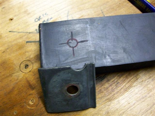
Using a 1/2" wood type bit with no lube.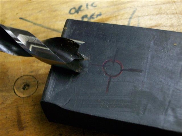
Slower RPMs worked well, backed up by drilling into a piece of wood. Trimmed boogers off with an Exacto knife.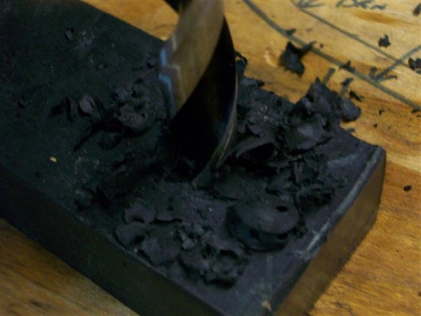
Stuffed in the small metal spacers.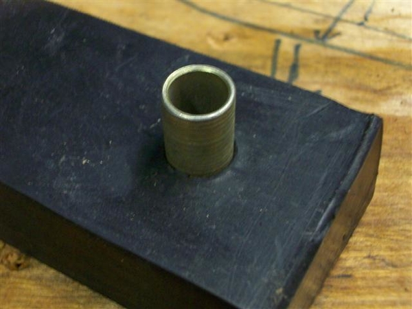
Dorked around with heights and marked the slots of the muffler brackets. Slots allow for slight height adjustments, or you can just make them to fit to the top of the slot.....I aimed for the middle...
Rear hangers are pretty much vertical. Front hangers deviate...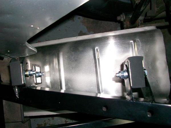
Tried to make things close to level.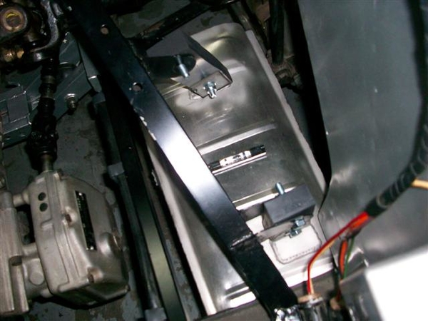
These cars are not symmetrical...
Fab'ing up the inlet pipes to the mufflers. Left side went fairly easily. Right side was a bugger...ended up Frankenstein'ing the pipe..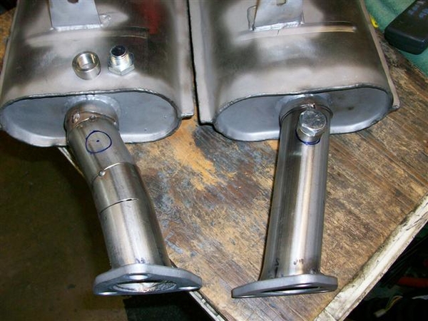
Franky!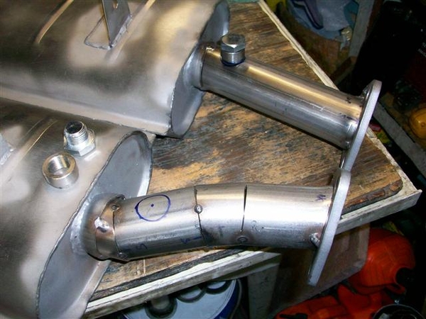
Mufflers are off at the welder getting the stainless steel welded up where I had to Frankenstein the RH inlet pipe... I tack welded everything in place.....let them pretty it up and put in the O2 bungs for me.
Tomorrow! List grows shorter! If I don't get it to smoke test Tuesday, Wed will be smoke and fire! OK, at least turn on the ignition, check for smoke, put gas in the tank and carb, and see what happens!!!
Ciao! More pics later.....it's late!
Steve
Attachments
Images (8)


Steve, O2 bung? what did I miss?
Denis,
The shop that I dyno stuff at once asked me if I had provisions for an oxygen sensor.... to help with tuning....so I figured why not! Also....just in case I ever lose more of my mind and decide to some day go to EFI.....I've got that part covered!
Nothing fancy!
Steve
The shop that I dyno stuff at once asked me if I had provisions for an oxygen sensor.... to help with tuning....so I figured why not! Also....just in case I ever lose more of my mind and decide to some day go to EFI.....I've got that part covered!
Nothing fancy!
Steve
Well,
This was supposed to be the final post! Got the car running tonight, but not yet drivable!
Worked on finishing up the final bits on my list....
Cleaned up the muffler outlet areas in the body and installed some heat barrier..."just in case".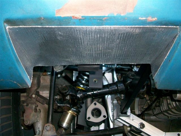
Picked up the mufflers from the welder earlier at lunch. Came out very nice!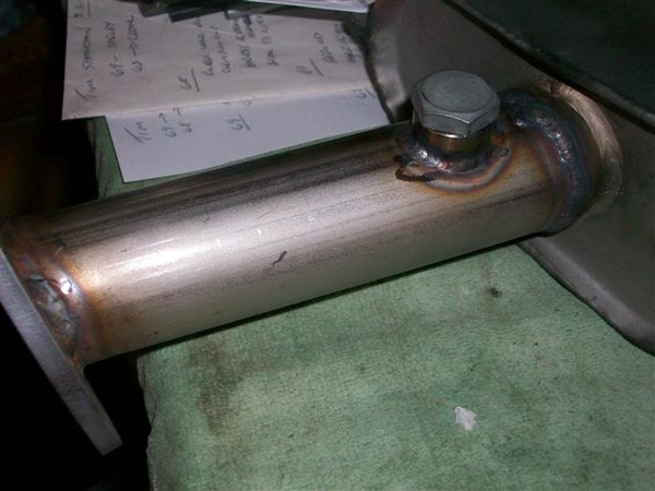
Fitted up the mufflers to the headers, tightened up all the bolts. Figured out earlier in the week that I shorted myself 6 of the little reinforcements for the muffler straps so ordered them from Wilkinson earlier in the day. Should be here by Thurs or Friday, but don't need them for now...
They look really good!!! Sorry, no pic's it was dark!
Son helped me put on the RH valve cover, spark plug wires, and fill the cooling system with water. Put some gas in the tank a little in the fuel bowls, a couple more quarts of oil in the pan and took the car down off of the 4" wood blocks it had been sitting on! Wow, back on the ground!
Fired up right away, but a fuel leak at the rear bowl inlet (my custom made transfer tube) had me scrambling to tighten that a few times....it wouldn't seal...but eventually convinced it that it wanted to seal!
Was running retarded, so tweeked the distributor a hair clockwise and she then idled up and smoothed right out! Warmed up nicely as one would expect with a new engine!!!
Ran it for a few minutes and then shut her down....only to find a water leak out the front of the water pump!!!??? HUH!
Found an extra mounting hole (probably for the alternator adjusting bracket when installed in a front engine config.....) that was open into the main water outlet! Now this the same water pump I was using before, so this is a mystery!!!! I know I didn't plug this hole previously! Or at least I don't believe I did!!!
As it cooled down, I dug around for a short 5/16"-18 bolt, lock washer and flat washer, and some Form-a-gasket and tightened it into the hole. Refilled the system with water, bled it again...and fired it up! Made a lot of difference as now the temp stabilized right away at the t-stat value..... fans on, no air into radiator ie external fan.
Here is a shot of the plugged hole. It is the center recessed bolt head in the center of the pic!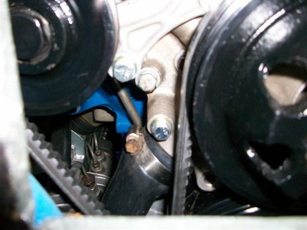
Ran the engine for about 10 minutes or so more, up to temp and then some, still haven't set timing, but keeping the rev's fairly low yet...rev's nicely very crisp throttle response with the Holley pretty much out of the box! Have not messed with idle mixture screws yet either!
Shut it down to clean up for the night...so I can get into work early....ugh! Checked under the car and found a tragedy!
The gulf coast has nothing on me!!! Texas tea...30W flavor!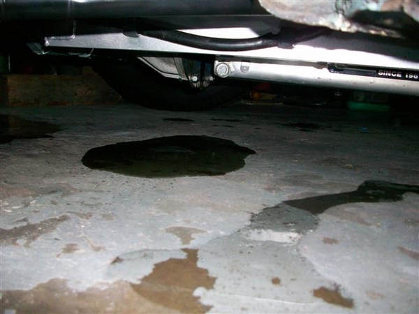
Something is amiss out rear of the engine. Either I totally pulled a boner mistake and forgot the rear main seal (single piece get's installed last....) when it was on the engine stand, or my one piece silicon oil pan seal got bunched up somewhere...or there is something amiss with the crank oil seal surface.....
Enough for tonite, took pic's, tossed kitty litter on the evidence, and closed down the garage.
The saga continues.... But it's gotta be something simple....!
Ciao!
Steve
PS: I hadta look! Checked the gasket set box where I had tossed all of my extra gaskets from intake manifold fitting etc, and didn't find the rear seal. So at least I put that in.... Perhaps not the proper direction, but I believe I was cautioned about that, and I double checked the shop manual too.... damn! That would have been too easy! Ok, not that easy to fix...but easy to figure out! Crap!
Attachments
Images (4)


quote:But it's gotta be something simple
So hope so.
Would LOVE to see that goose drive into Monterey.
Larry
Well,
Gonna be one busy guy for the next couple of days....
Figured out why there was no rear main seal in my gasket set...... Because there WAS NO rear main seal in my gasket set! If I wanted one, I needed to purchase one separately....or get a "CS" (complete set) to have one included.
Found incriminating evidence in my pictures that I took during engine installation.....that I did NOT install a rear main seal in my engine!!! Silly 5.0L engines.....
As my wife says sometimes while un-knitting..... "rip and tear" that mistake out!
Chalk one up for experience!
Steve

OK, let's just say for all practical purposes, this was a TV show, with say Chip Foose in it, the cast is assembling an exotic "make over car" and one of the mechanics forgot to install a seal somewhere.....since they were going to tear the car apart again anyway before final assembly, it really didn't matter much. Just a PITA!
EDIT 04/06/20 I built the new engine in 2008 and it didn't get around to installing it for two years, as the car was running..... When I tore the old 'Bird engine down and after the initial assembly, I left the rear oil seal hanging around on my work bench for some time as a reminder to get a new one. (Well that didn't work....... !!!) I eventually got tired of working around it, and rather than tie it to the engine/stand/etc as a reminder, I tossed it in the garbage telling myself that "I would remember this!" HAH!!! How we lie to ourselves sometimes!!! ![]()
![]()
![]()
If you scroll back up to my post on 7/12/10 (page 4 of posts) the top picture of one of the posts has the rear engine view as installed finally in the car. You can just barely make out there is no seal..... This is a low res pic, but on my higher resolution original I could see that I had no seal installed!!! At the time, this was consuming so much brain time that I couldn't get to sleep, so I came out to the computer and cruised thru all my old pictures until I found that picture and realized what I hadn't done!!!!
I've reposted a better pic with no seal for your convenience!
End of edit! Cheers!
Seal not in place: BIG GAP there! DUH!
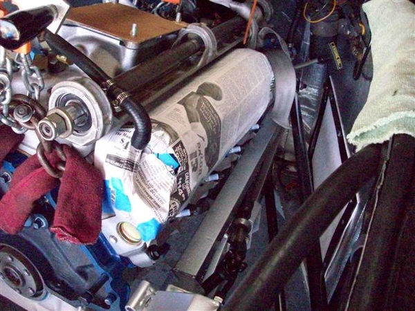
That's my story and I'm stickin' to it!
So now that I have torn every thing apart and installed the rear main seal, as my last task in the engine rebuild....I've started the reassembly process.
Seal in place: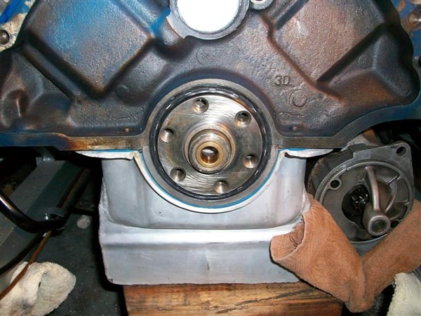
Local shop recommends a fine coating of sealer on the outside of the seal. My 91 shop manual references a section on installing this seal several times....there is no section! (21-1...)
Patience, a 1" steel punch of sorts, and a plastic mallet was all that was needed to put the seal in place. A thin coat of oil on the inside seal area...and tap it in flush with the rear of the main cap.
After de-oiling all of the flywheel, block plate, bellhousing, flywheel bolts with solvent, I put that all back together.
Flywheel bolts got "The Right Stuff" on the threads.....(found the ARP thread sealer with Teflon later....), Ford Tech says used RTV and torque to spec.....75-85ft-lbs.
Torqued the pressure plate bolts to 15ft-lbs on the aluminum flywheel. Used a conventional alignment tool for the disc, which proved effective as trans slipped right in place! No muss or fussing with mis-alignment...
Here is a shot of the front of the ZF with the throwout bearing in place.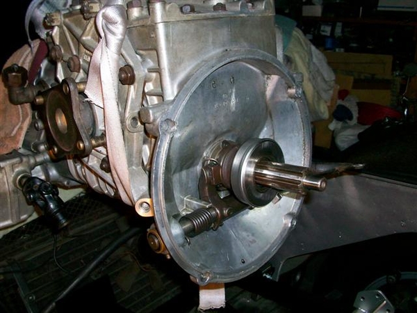
A few more shots of the ZF going in. Tipped the rear of the engine up (disconnected exhaust at the flanges). It should be noted that this time, I removed the rear ladder bar. This gave me a LOT more room to work with to get the trans in place. Should have done that the first time!!!! Excuse me, I meant during the "trial run"!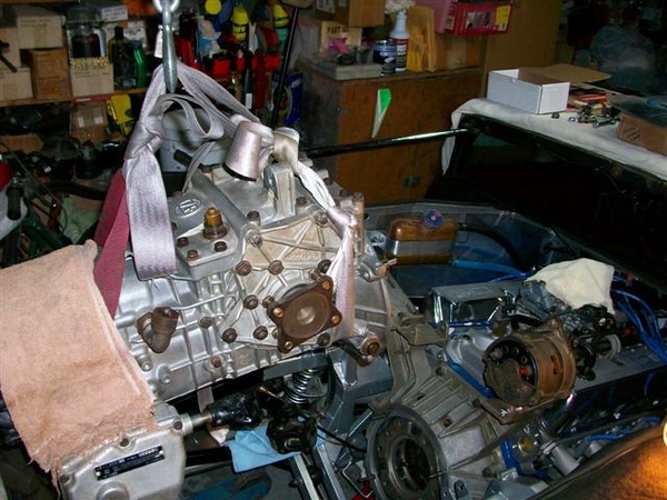
"Easy does it" is in order running the engine hoist. A few towels to keep paint on the metal bits...and the fancy sling made up of old seat belts! Works great!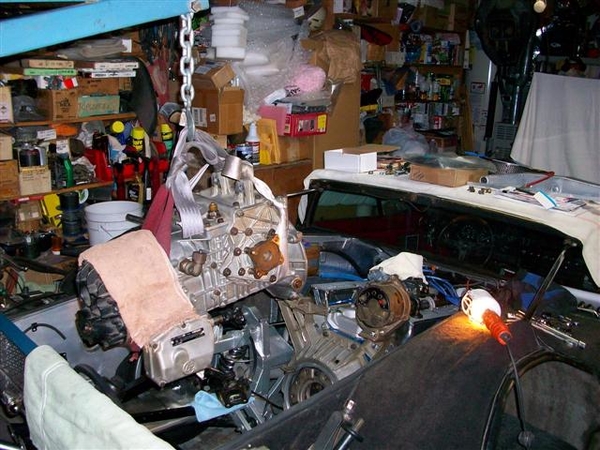
The seat belt sling actually allowed me to lift up on the rear of the trans to give me a slight nose down attitude. Setting the towel, folded up a few times, on the rear spare tire support worked great. Just have to watch out for brake lines etc.... basically everything!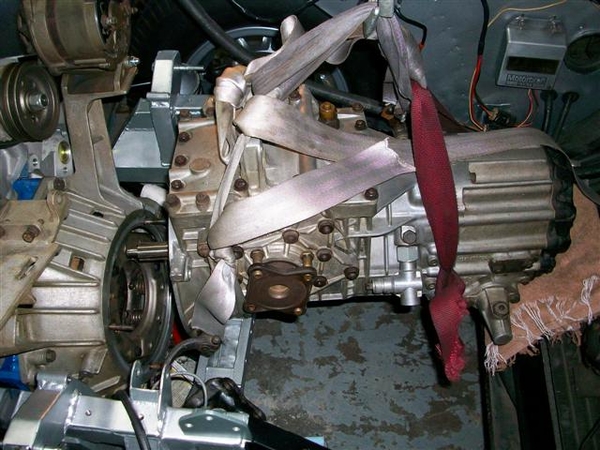
Lower real slow, check to see you are not hanging up on the studs and bending them!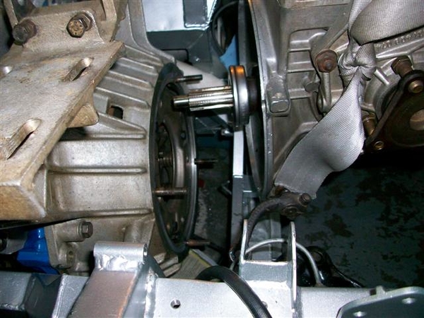
Almost there....slight pushing and pulling and minor up/down with the hoist and it slipped right in place with no opposition! Wow! That is a new concept!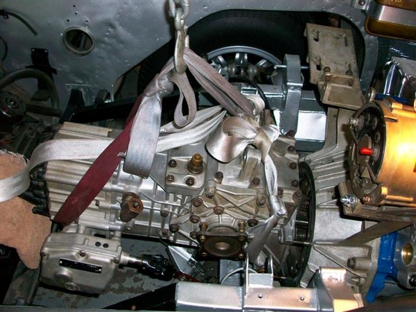
And here is where our hero left off tonight.....ZF is sitting in place (on a 2x4 on top of the cross member) and is bolted snugly up to the bellhousing!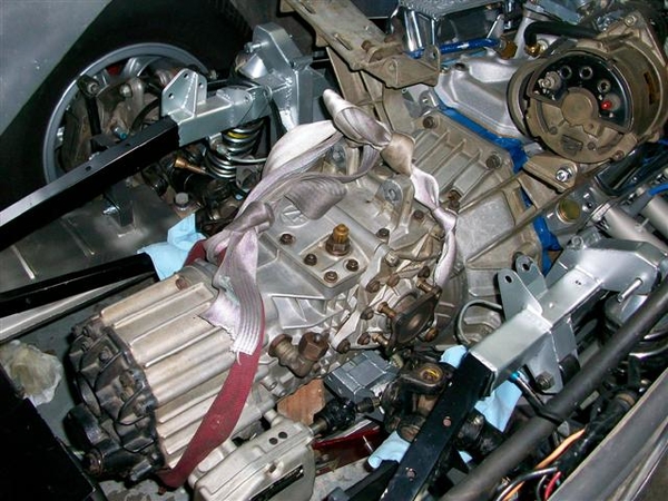
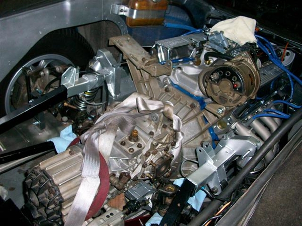
Tomorrow I can finish final tightening of everything else, reinstall the crossmember, ladder bar, sway bar, exhaust bolts, axle connections, speedo cable, shift linkage... adjust the shifter mo' better, and may be see if I can get out of the damned driveway with my new lower oil pan!!!!
Time for some sleep so I can get my butt home early to dive back into this!
Ciao!
Steve
Attachments
Images (11)


Add Reply
Sign In To Reply