
I started on my engine swap last week. Have been working on the new engine for over a year, with other stuff thrown in for fun & distraction...and it has been easier to just turn the key and drive the car....but I want to have it installed for the 40th anniversary of the production Mangusta, and drive it to Reno for the annual POCA convention in June!

Needless to say, the process of taking out the ill fitting and worn out Boss 302, and fitting a new 5.0 based 302 has been a challenge!

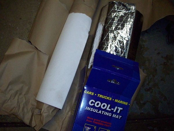
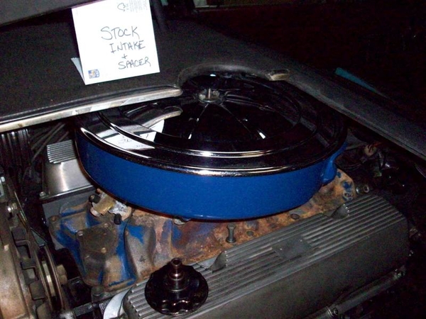
One of my major goals was to fit the stock air cleaner back under the shields, so that I can draw cool air into the engine. I always had cooling issues, exaggerated by Las Vegas temps on every visit, and this last year, found out that I need CLEAN air as well!!! Those of you that watch the DeTomaso Forum know what I speak of.... I also wanted to have the car look a little more stock, since my car came with a lot of the original parts still in tact. Perhaps chromed, but there!

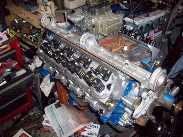
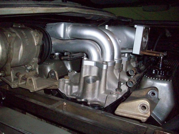
Another goal was to use a 5.0 based roller cam block and use "off the shelf" parts. In this case, aluminum Motorsports Y303 heads, and an Edelbrock RPM intake, Holley carb, and the stock air cleaner.

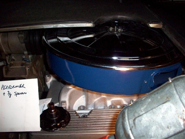
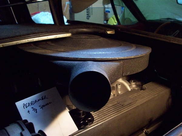
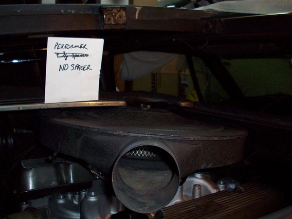
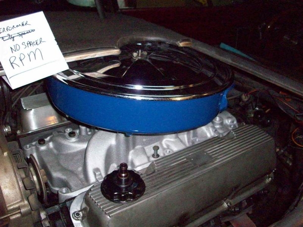
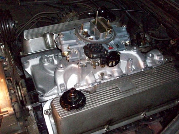
All of my calculations and measurements on the engine stand were coming up bad. The RPM model was too tall. So, I had an Edelbrock Performer modified to fit the tall port Y303 heads. It turns out to barely NOT clear the hatches according to the calculations as well!!!!

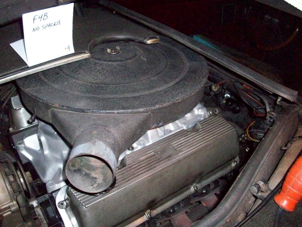
I bummed an old Edelbrock F4B from a friend after an owner up in Reno said, "yah I have an F4B and the stock air cleaner fits just fine! Well, again, my measurements said otherwise....

I was beginning to doubt my abilities to run a Stanley tape measure!!!

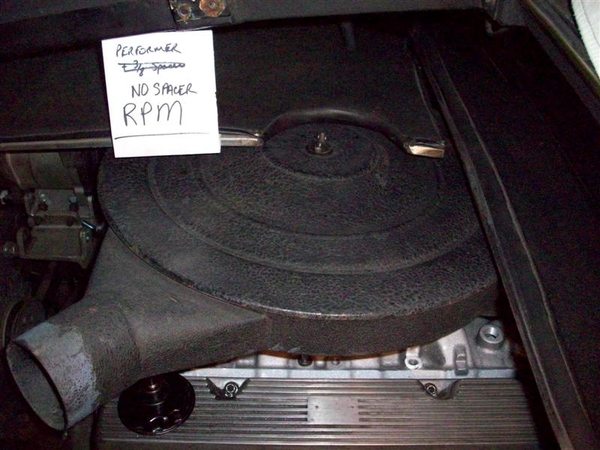
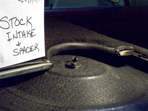
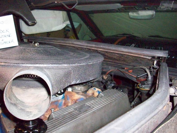
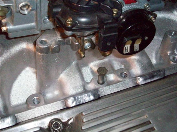
So, I borrowed a C8ZE (stock cast iron) intake and carb spacer from another buddy and figured that this would end all issues.... It didn't. In fact the stock setup was only a matter of thousandths of an inch shorter than the Performer RPM!!!! Something is wrong here.

So, since I was doing this all on the engine stand, and comparing measurements to known similar/same points in the car and it was only serving to frustrate me, I made the decision to begin this odyssey once again.

Last time I did this, it was 2001. That was the first time that I had the car back together, after receiving it in various boxes and loose parts, that I drove the car with any sort of confidence and any sort of distance! It turned out to be quite an adventure including bottoming out the on the bellhousing not 15 miles from the driveway, a speeding ticket 2 miles further up the road and an oil pan repair in Barstow CA on the return trip, but we made it there and home, and have done it every year since then....including more adventures!!! It has been the ONLY Mangusta in Vegas for 7 years! nudge nudge wink wink!

So, please follow along with me as I attempt to document this process in word and picture....as soon as I figure out how to add pictures properly without taking up too much server space!!! (My avatar photo was taken in 2001 as I thrashed to get the car on the road!)

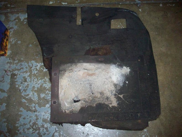
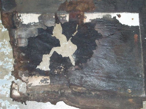
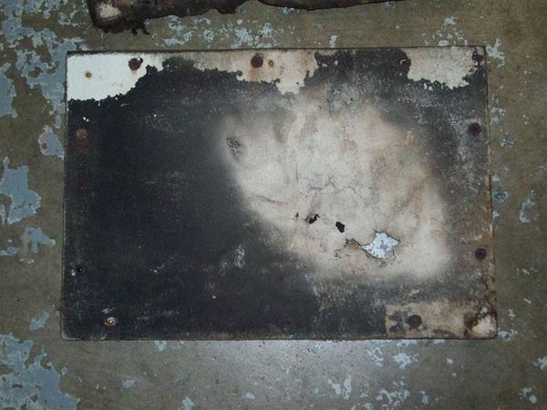
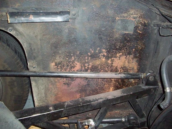
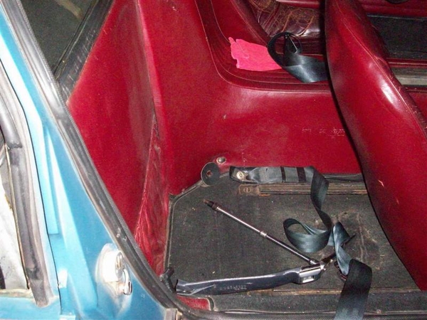
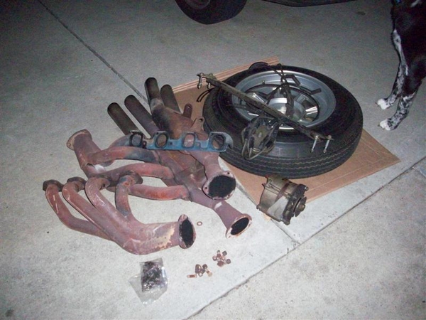
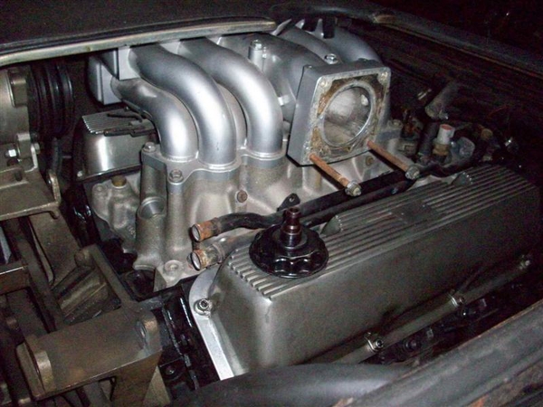
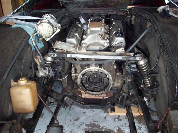
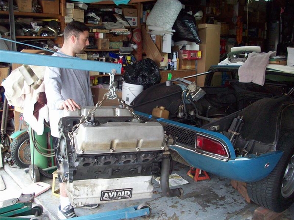
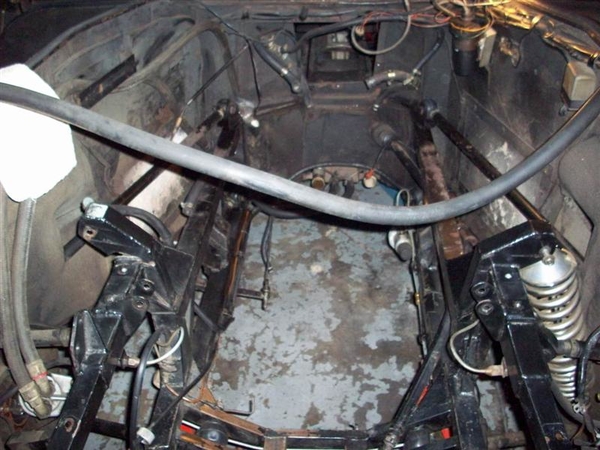
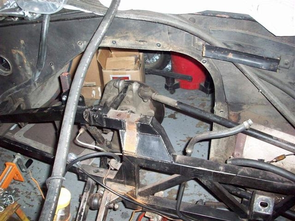
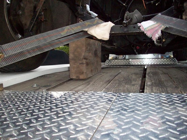
Day 1. Hatch off to begin test fitting manifolds and eventually install new engine.
 
dayone1dayone3

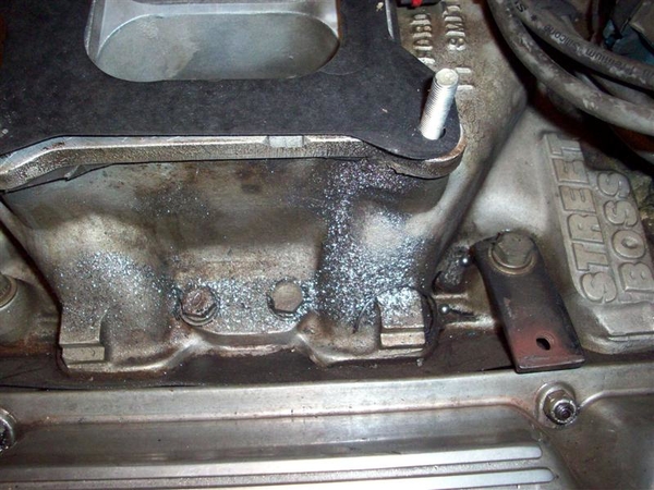
My Boss 302 installation. Note modified hatch cover and missing hatch cover stand. Also how tight the smaller diameter air cleaner is to the hatch. There is actually tension on the air cleaner by the hatch covers. (Aussie 2V heads with Street Boss intake on a Boss 302 bottom end.)


More Later!
Steve

Attachments

Images (2)
  • dayone1
  • dayone3
Last edited by mangusta
Original Post

Replies sorted oldest to newest

Day 2.

I removed parts and pieces so that I can pull the intake and begin test fitting intakes.

First was removing the interior, seats and console to get to the front of the engine to disconnect various bits. I also started draining the cooling system and the oil.

I have installed seat belts from a mid 90's Thunderbird. Rear seats I believe. No shoulder belts. All attaching nuts were already welded to my chassis. I had to cut the holes in the console leather and I did have to shorten the Ford bolts, but the threads were a match! Picture shows bits and pieces with console still in car. I used a piece of leather to cushion the load on the console leather as it had shrunk and pulled away from the fiber glass, to prevent tearing.
 

Here is a shot backed off a bit.
 

Then things got real crazy when I found this. I had noticed my clutch slave hose was tight on the "ladder bar" that connects the two shock top mounts together...


NOT GOOD!!!


Front side view:
 

Here is a shot of what is left of my center jackshaft bearing. This went south on my way home from Vegas this year. Since I was planning on replacing this whole mess anyway, and since the other two bearings were fine, I didn't bother rushing to repair anything. This is with the jackshaft bracket was removed....and I found this residue hiding....


Magnet worked to retrieve the big parts!
 

The removed parts pile for the day.


Intake came off after I cleaned up all the metallic bits and blew it off with air and a vacuum to catch some.....

First test, Performer 289 Intake, 3/8" spacer (to help carb clear the jackshaft)and a 428 Ford air cleaner. OK fit! But I'd hate to cut up a $500 air cleaner base to do this!
 

Now the stock air cleaner. Interference at front panel and at rear air tube connections. Removing the spacer resulted in only a slight touching of the front panel. Rear was OK.
 

Here's a shot underneath showing no spacer.
 

Top View
 

Now I switch to the Edelbrock Performer RPM, carb and stock air cleaner. No carb spacer. Note interference at rear of the hole cut in the shield and the gap at the front caused by the air cleaner hitting the front panel. No way a spacer is going to work!
 

I tried the 428 air cleaner just for kicks... slight touching at front, ribs on shield would probably just touch the air cleaner top.
 

Now for the vintage F4B Edelbrock that supposedly fits! No spacer, no way! Note gap at front! Contact at rear of hole.


The 428 air cleaner had some touching at the front and probably at the rear again....

STOCK AIR INTAKE MANIFOLD...this has gotta fit, right???
 
NOPE!

This shot shows how the front panel doesn't fit down....
 

428 air cleaner actually fit well! Note the light you can see in the gaps!
 

OK, enough intake madness!!!

For those of you wondering how I can test regular intakes on a set of Boss 302 type heads, note in this shot that the two center bolt holes are in the same location! This is a shot of the Performer intake with extra metal added onto the top so that they would seal better to the heads! (RPM has this metal cast in place...)


Tomorrow, more discoveries!

Steve

Attachments

Images (22)
  • blobid0
  • blobid1
  • blobid2
  • blobid3
  • blobid4
  • blobid5
  • blobid6
  • blobid7
  • blobid8
  • blobid9
  • blobid10
  • blobid11
  • blobid12
  • blobid13
  • blobid14
  • blobid15
  • blobid16
  • blobid17
  • blobid18
  • blobid19
  • blobid20
  • blobid21
Last edited by mangusta

Day three.

When I sent my original email out to my private Goose mailing list a few days back, regarding jackshaft bearings and my intake issues, Dana Hansen of Mangusta International fame answered back saying that his engine was out currently and that he could measure anything I needed...

So, I took him up on it. I measured from the top surface of my engine compartment to the top of the frame rails (at rear of engine/bellhousing parting point) . I also measured the height of the frame rails <2">, and the height from the bottom of the lower frame rail to the top of the engine mount bracket , typed it all up and mailed it off to Dana.

A matter of minutes later, (while I was removing a scad of other stuff to be listed later...) I got a note back from him with a picture full of blue masking tape and black numbers and arrows! Imagine my surprise when I noted that his dimension for the engine mount bracket was only 5"!!!!

Here is a view of the right hand mount, outside of the fame rail. Note the extra seams!!! Frankenmounts!!!
 

Left mount, again outside of frame rail.
 

At last!! I finally know what my problem is! The previous owners had to raise the Boss 302 to get the exhaust ports raised above the frame rails.... It was either raise the motor or lower the frame rails..... I guess raising the mounts was easier!

Some more shots dinking around....trying to fit my NEW jackshaft bracket and idler pulley bracket to the motor with a stock intake, to get a baseline to determine how far off a different intake would put stuff....


View of new bracket on engine. Note that the rear bearing is now a 52mm diameter where all earlier versions were 47mm!!! (I was able to find bearings easily to fit!)
 

Mismatch of idler bracket to front of J/S bracket. I will need to do some work on this...machining rear mounts of idler bracket and perhaps welding up the holes and redrilling in proper location.
 

Spot facing of J/S bracket may be needed too. This is not a "snap together" project!
 

Enuf for now!
Steve

Attachments

Images (5)
  • blobid0
  • blobid1
  • blobid2
  • blobid3
  • blobid4
Last edited by mangusta

Day three and a half/four!

Here is a list of stuff that I worked on disconnecting etc on day three and into day four.

Jackshaft is already out, rh idler bracket, as is intake.

Water pump pulley
All belts
Coolant overflow tank
Heater hoses
Alternator
AC compressor mounts
Oil Temp sensor wire
Oil Pressure sensor wire
Fuel line
Oil lines (remote filter) and filter adapter
Starter wire and bolts (starter is held captive by pan and frame rails! Don't drop it!)
Bellhousing lower shield bolts (3)
Header bolts, and mufflers
Clutch slave cylinder
Speedo Cable
Shifter linkage roll pin

Loosened bellhousing bolts
Shock upper mount bolts
ZF crossmember bolts
Axle flange bolts (removed two each, left two in case I move the car, don't want axles flopping....)

Disconnect any coil or distributor wires, temp sensor wires. Throttle linkage.

Have ZF bolts to loosen yet, to bellhousing. Will do these just before removing ZF. I don't try to pull the whole thing out as one assembly.

Here are some shots of an intake manifold that would fit just fine!!! Don't think I'm not thinking about it!!!!
 

This is a modern "GT40" tubular intake for fuel injection. Jackshaft bracket would require modification to clear injectors...and I'm not quite ready to cut up my brand spanking new one just yet!!!
 

Plenty of clearance!
 

But, I need to find a place to hide the computer and wiring, add a high pressure pump and return lines...PLUS troubleshoot the whole danged thing.....before June....

Here is a shot of my current oil pan... that will be dropping down at the front by over 1.5".....note the bracket for the brake proportioning valve sticking down....it has lost some material on my driveway....!!! Oil pan will now be lower! ANGLED entry and exit from the driveway! No head-on moves!!!!


I guess I could shorten the pan....I believe it is a 9qt (with remote filter) capacity, and is fully baffled. If it were to be cut back to 7qts that wouldn't be a large deal I don't think...but perhaps taking a half inch to 3/4 inch out may be in order....


I also found this pic of the Right Hand mount, but picture from the inside of the frame rail. Note my 57 Chevy rubber biscuit, the Frankenmount welds, and the top of the brake proportioning valve.


Maybe I can come up with a stepped mount such that when I decide to put in the GT40 EFI manifold, I can easily raise the engine back up in the front?????

To date, she sits waiting for time to part the ZF and engine. Maybe Thurs eve....or the weekend... Did some calling and ordered jackshaft bearings from a local bearing house. Ordered spares.....for the traveling tool box.

Ciao!
Steve

Attachments

Images (7)
  • blobid0
  • blobid1
  • blobid2
  • blobid3
  • blobid4
  • blobid5
  • blobid6
Last edited by mangusta

Day Five/Six ish.

OK, finally got back into it this weekend. Took the ZF out, bellhousing/clutch, and eventually the motor. Took some engine compartment shots for "reference" to help me with what it looked like when it was still working......

NOTE: If you haven't recently checked the torque on your bolts that hold the axle shafts to the flanges, do it! Mine were replaced with new bolts/nuts about 20K miles ago, and I found a couple that were starting to loosen a tad. I will add this task to my "oil change" list....stuff to do to the car when you change the oil.....

Getting the engine out was interesting, since I had to remove the trans cross member and the ladder bar and due to my cracked shock mount, made that task all the more interesting, as any pressure in the form of weight on the LH wheel made the crack want to go BIGGER!

So, the LH frame rail found a jackstand holding it up....while the engine hoist went in over the RH tire on a diagonal course. The boom arm was not long enuf to come straight in from the rear.

Once the engine was out, I put a jackstand on the RH side of the frame too, but left the wheels on with blocks underneath....we are in earthquake country after all.

Trucked the LH hatch and spine down to the mini-storage for safe keeping while I clean up the chassis and ready the engine for installation. Cleaned up the ZF, bellhousing, and all the rest of the greasy parts that came out. Better to do it now....next time I touch them, they'll be clean! That ZF is one heavy piece of aluminum.....!

Good things: Clutch wear on the kevlar/kevlar disc looks fantastic! Wear on flywheel and pressure plate is non-existent! (No pic yet!).

I did think that I made a mistake in my pilot bearing though, by putting some grease in the hole before putting the trans in. This is a no-no, as grease will clog the holes in the sintered bronze and prevent oiling.... Oil is OK, but grease is not! Polished the ZF input shaft up with ultra fine wet/dry paper and parts cleaner solution. Looks great! May need a new pilot bushing....

OK, here are some pic's of the efforts.

Mismatch in the ZF cross member area, RH side. Tension on the frame.
 

I had to rig a tie-down strap to release some of the pressure, in order to get the bolt out...
 

Missing the pic's but basically used the engine hoist to lift the ZF while maneuvering it out. Sort of a counter clockwise rotation of it worked, until it could be lowered out the opening just aft of the axles. The top ears fit thru the tailpipe slot in the rear valance area, so I didn't need to lift the car up any further.
 

Here is what is left......
 

What I found when I pulled the bellhousing off, and the pressure plate. Guess I will be using some different lock washers.......
 

The discard pile for the day!
 

Out comes the engine. One less stressed mechanic when the engine got this far... Getting the hoist in there is a puzzle of sorts....and easy does it moving it up and out...over the charged AC line!
 

That was it....plus cleaning up greasy parts. Loaded the engine onto my trusty shopping cart just for moving such things and moved it out on the side of the garage for storage, and eventual stripping of Goose bits from it, pulleys, idlers, pilot bushing adapter, and oil pan.

Steve

Attachments

Images (7)
  • blobid0
  • blobid1
  • blobid2
  • blobid3
  • blobid4
  • blobid5
  • blobid6
Last edited by mangusta
Steve,

I'm sure there are a bunch of us who are following your project with great interest. I too REALLY appreciate you putting all this work into posting your progress for the benefit of the rest of us. I really wish I was closer so I could come over and scrape some knuckles while learning first-hand. Many thanks and good luck!

Mark

Day 7.
Thanks guys!!!

I had forgotten how much fun it is to climb in and out of a Mangusta chassis.... Now that the hatches are off, it is the only way to do things, if you don't want to lay on your back and work, although some of that is required too whether you want or not! Kicked one blade of my AC condensor fan with my timberline and sent half of it flying.....ugh. Put it on the list...

Was going to start washing down the frame rails with solvent tonite, but it got to late to be stinking up the place....so settled for popping off the motor mount brackets (the 57 Chevy fix..) and the LH shock and wheel so that I can get at stuff. Also pulled the axle shafts for cleaning and inspection again.

Motor mount brackets: When you drill and tap 1/2" steel for threads, be sure to used anti-seize or something on the threads. If you don't, PB Blaster (or similar) is your friend!

Axle shafts: Said this before, if you haven't checked your nuts for proper tightness.......do it! Found a couple that were....not exactly tight. May have one u-joint going south, saw just a little play in a cup. Need to check clocking on shaft too. Was 90 degrees out, which I think is ok. Run them at 90 or 180 out, but not anything in between....

Shocks: Pleased to report that the QA1 shocks and springs I used out back are holding up nicely. They have a nice thin coating of road dirt and engine oil/gas film on them that has yellowed the finish a tad....a nice patina! I've told others that I am not a fan of chrome on springs. Great on a hot rod where they are out in the open and you can get to them....not so much on a street car where they are buried. The powdercoated silver is a better surface. It won't rust. Not sure how much chrome polish I want to invest here..... Have cracks to weld!! One good thing is that the ball ends on these shocks seem to be holding up well! Upper on the one shock I removed is just a tad loose, bottom one still feels tight. (Non-lube versions. I think I have 17-18K on them.

Will hope to clean these parts up real quick Tues and take some pictures! Start washing down the grime, and get ready to strip some paint near the cracked area.

Here is something I need feedback on. Not sure if this is a factory modification or an owner mod. Here are pictures of the ladder bar (upper shock mount frame brace/spreader for lack of better description!) and the RH upper mount from car #1134, also getting an engine-dectomy at this time.

 
Note that it has 4 thru holes for bolts. On mine, you will find only two mounting holes. (See two pics up into days 5/6 to see mine.) Note the inboard holes on the one above, and the absense in my bracket. They correspond with the extra "tube" welded on to the top of the mount as seen in this pic.


Compare this pic above to the 3rd pic of mine, in day 2 way back up top!

I'm gonna guess that all four holes in the ladder bar are not just thru holes, but have inserts welded into them for support. Then it was chromed, similar to mine, but not from the factory. My car is #878 (March-April 69 build-window dates) so did the factory have problems with cracking mounts in late 69??? I do know that much later cars had yet different upper shock mounts that tied into the rear sheetmetal.... Have an old photo somewhere of a Goose that showed up my first year in Vegas. I think it was #1254 or so, and this area of the chassis was markedly different in design!

How many of you have a four bolt ladder design or something different??? Would be nice to know! Perhaps there is a fix or mod that more of us can use?

Attachments

Images (2)
  • blobid0
  • blobid1
Last edited by mangusta
Mark,
Fantastic! Just what I was looking for! Your car was built 10 cars before 1134, so your pic' proves the extra inner 3rd and 4th bolts thing was done at the factory! What 1134 is missing, is the wings that go from the top of the shock bracket up to the frame! (This is what I saw on the car in Vegas, #1254ish) I can just see the "punched" holes that lighten and strengthen it, but what does it weld to on the side of the engine compartment!??? What is odd, is a modification that occurred later.....or #1134 passed #1114 on the assembly line.....

Your jackshaft pulley is an odd one like none I've seen before! As is the valve cover bolt arrangement....That's a unique setup I thought reserved to exhaust pipe bolts on Harleys, so that you don't strip out the cast iron.... Not a problem typically with VC bolts on Fords!

Looks like you've got a good solid car to play with!!
Thanks for the shot! Take one of the top of this bracket, where it attaches to the chassis/engine compartment, perhaps it can be duplicated!

Steve
Steve- pull the top cover of the ZF off and check for the presence of safety wire. 8MA-0760 had the ring gear wired with .060 thick wire- maybe from the Factory? I always use .032 ss; .060 wire is good for ships and locomotives....
If you don't do this and you ever have ring gear trouble, I will say "I TOLD YOU SO" several times a week for years to come!
Steve,

Is this any better? The car is in my shop under cover and I only have the photos I took before I put her away in the fall. I can snap a bunch more and take whatever dimensions you'd like, but you'll need to guide me like the blind to get the right details.

Mark

Attachments

Images (1)
  • IMG_1019

Mark,

First let me say that no, I was hoping to see the top of that piece with the hole punched in it, top left in your last pic! To see how it attaches to the body and provides any support for the shock and frame, to keep it from flexing.

Secondly, that is one god awful job of welding on the bottom of that piece, where it joins the shock mount!!! (look just above the top of the shock) I hope it is grease and not welding!

Third, check out the top of the shock mount where it meets that welded piece. Is that a crack going horizontally about an inch??????? You need to check that out!

Day Eight.

Not much major today. Received two samples of window channel weatherstripping, #21 and #22 from JC Whitney to try out. They are not a good fit IMO, so am going to ask for a sample of #24. It is the last hope of what they offer, to work. The #24 is 1/2" wide but the channel is .650" wide, yet the wider stuff was too tall and stuck out of the channel too much.... IT is also a little shorter, so I hope that it will work out. Worst case, some adhesive should hold it in place nicely. Their listed dimensions are more like estimates.... or suggestions! We'll see....

I cleaned up the parts that I removed yesterday and tweeked on the half shafts since I found one of them clocked out 90. BossWrench confirmed that they should be in phase with each other and NOT 90 degrees out.

So, I took them apart and cleaned everything up real nice, then realized that I need new cork seals in them. Anyone??

Here are the bits I removed yesterday. This is after a bath in parts solvent. Got the greasy stuff off, but left a fine yellow tint...of burned dino oil....? I'm not going to get into polishing stuff to a bright sheen only to have it garpy the first puddle I hit, or the first long drive behind a bunch of Panteras....oozing unburned hydrocarbons all over the place... Smiler

Clean is good. It will match the rest of the car better! I just want to be able to tell when something is leaking or amiss easily without wondering if it was from last years disaster..or the year before...or...!

The shock is a Carerra (Now QA1) chrome economy model, fixed 60/40 valving with 400# spring. (I would do a painted shock body and silver powder coated springs in the future, paint the shock green to sorta mimmick the original deCarbon....
Motor mounts are 57 Chevy rubber biscuits with a thru bolt and a custom "non-rotating" overkillmaximus nut thingy.... I may shave some weight and substitute a washer and a nylock here.... Smiler

On the half shafts, notice where the one on the right does not have both center shaft u-joint cups facing up at you like the LH one does!


NOTE: I now have PROPER MANGUSTA replacement motor mounts available for your cars!!! I did not show them at the time I was doing this portion of the swap... they might show up towards the end of this thread!! So what you are seeing here is simply historical stuff from my car! If not, I have them posted over in the For Sale section of this site. Steve

Here is a shot of the motor insulator affair. It is a design that came with the car and I simply carried it forward since it was working. Once I lower my frame mount brackets, I can afford to use the correct style mounts that were located recently by another Gooser. If I need more clearance still, I can put something like these back in easily.


Closeup of my maximusantirotating nut thingy.... big chunk-o-steel shaped to fit the recess of the aluminum mount, drilled and threaded! It works. I didn't realize that you can't pull the motor out with these mounts affixed to the motor. You need to install these first to the frame, then you can drop the engine down on top of them. My idea was that with these things, you could swap the biscuits without much effort! Good thinking, but not needed!
 

Here is an exploded half shaft. Made by Spicer Hardy. Pretty simple. I marked the u-joint cups with a grease pencil so that I could get them back together the same orientation. Threaded round cover on the RH side has a tin retainer and a cork seal. Loosening this threaded cover allows you to slide the two pieces apart.


Here is a closeup of the cork gaskets. Gonna see if I can find them locally tomorrow or Thurs at Motion Industries.
(3-18-09 OK, MI doesn't carry these Spicer Parts. The cork seal part number is #3-16-53. Now to find a dealer that will sell a small qty! (2))

The bent tin piece (washer is what they call it) is actually deformed from taking it off of the shaft. It is soft metal and forms back in shape easily. The ends of the cork piece are actually tapered so that they nest in each other once installed! Nice detail! One of the threaded caps was not going on very far, and the threads are very fine. I show my "thread file" (#1) that is an extremely handy tool! Seems that these threads are a standard thread and are a 24 per inch type! Lo and behold, the thread file had a #24 section on it, so I sat and cleaned and reshaped threads until I could get the cap threaded on far enough so that it would compress the cork ever so slightly. There was paint in the threads and a couple of tiny dings. These files serve to realign material and will not remove much at all if you take your time and get the "feel" of when you are in the groove....and not cutting new threads!! Smiler


Took these pics, and then gave the rear of my chassis a towel bath with a solvent soaked wash rag, and a clean light colored towel. Clean with the rag, and then polish with the light color rag! IF you get dirt, you missed..... re-solvent, re-towel.... At least next time, I can climb into the rear with a solvent pan and I can wash down the rear lower (greasy!) cross member and the front frame rails, without getting all full of crap! Maybe a little, but not a grimy disaster! Work clean weedhopper!

Steve

Attachments

Images (6)
  • blobid0
  • blobid1
  • blobid2
  • blobid3
  • blobid4
  • blobid5
Last edited by mangusta
quote:
Originally posted by Mangusta:
I was hoping to see the top of that piece with the hole punched in it, top left in your last pic! To see how it attaches to the body and provides any support for the shock and frame, to keep it from flexing.

Secondly, that is one god awful job of welding on the bottom of that piece, where it joins the shock mount!!! (look just above the top of the shock) I hope it is grease and not welding!

Third, check out the top of the shock mount where it meets that welded piece. Is that a crack going horizontally about an inch??????? You need to check that out!

Steve,

Thanks for the concern, but that "crack" is an optical illusion because of the angle of the photo. Here are a few pics of the bracket. And, yes, that is one of the fugliest welds I've ever seen. I'm pretty sure that even I could have done a better job on those. Check out the "secure" method of attaching that bracket to the frame! At least it LOOKS cleaner than those welds.

Keep up the great posts!

Mark

Attachments

Images (1)
  • IMG_4589
Mark,

Great shots! Those pieces really don't look like they'd do all that much, but perhaps it is "just enuf"....

OK, played dig in the Spicer website (www.dana.com) to try and find out info on the cork seals and the half shafts in general. Actually they are "drive shafts" just short...

Cork seal has a number: #3-16-53

Shaft pieces have numbers too!
Slip Yoke assy:3-3-118KX
Dust cap and washer (and cork) kit: #D3A
Yoke assy: 3-82-268X

These numbers do not include the parts that bolt to the hub axles, or the ZF.

U-joints remain to be found yet!

Will update this when I find a dealer that will sell small parts in case you find one that is wanged out of shape, or need cork seals too!

3-19-09 UPDATE. OK, it appears that Dana Spicer is the only remaining portion of this perhaps otherwise British company, here in the US, and has entered bankruptcy! The company that bought them up, is not selling much of the products and it was uncertain how much will be available in the future according to the person I spoke with at a local driveline shop!

Bad news....good news..... the cork seal listed above is not commonly available here or in Australia, the only other continent that seemed to be offering Hardy Spicer/Dana parts.... What IS available is called a "Dust Cap Assembly" #D3A and IS available locally. Check a DANA Spicer driveline shop near you! What the #D3A "cap assy" consists of, is a new threaded cap, the metal washer, AND the cork seal! Aprox $12-14 each. I ordered a pair from a biz by the name of Driveline Service in Pittsburgh, CA. We'll see how they come out!

On other good news bad news....my bearings that I ordered for the jackshaft are in....but it would appear that an opportunistic employee of the bearing company "may" have hijacked my credit card number and a few others.... authorities are now investigating..... made for a crazy few days of phone calls and no credit card with which to buy more parts! Frowner (Credit card co. actually flagged the bogus transactions and shut my card down almost immediately! Smiler )

Steve
Last edited by mangusta
quote:
this is the best thread on the board right now ...

Keep those pix coming! I totally appreciate it when pix are included with posts ... I learn a ton more!

Agreed! And if you don't have one of those thread files Steve mentioned, get one! I have one and I can't tell you how many times it's saved my derriere! Just need to get a metric thread file now.

Attachments

Images (1)
  • thread_files2
A great BIG box arrived today..... with my new mufflers inside!!!! You and I will have to wait to see them.... Frowner I am heading out of town for the next few days and won't be Goosing.... I will be preparing a beautiful 1969 Torino Talladega for sale, as well as a few other odd cars, like an original 1962 V8 Comet station wagon, an SVO Mustang, a Turbo T-Bird, plus a few more... and a BD-5 airplane kit! All remarkably rust free examples! And a host of spare 427/428/429 parts.... Helping a friend that has decided it is time to liquidate his collection but he is physically unable to manage it himself, so a friend and I are undertaking this crazy task!!! Hope it doesn't rain too much!!!

Ciao!
Steve
Hey Steve, I know you are familiar with the Boss 302 here is a pic to prepare you for that big block 429. Here is a '70 429 CJ and a '71 429 CJ 4 bolt main. Tons of torque all day long. Drop me a PM if you need parts for that 429.... Too bad they are too big for a Cat or Goose Frowner
Denis

Attachments

Images (1)
  • RB1_262s
Last edited by denisc
Denis,

Now that's some serious heavy metal! Still has the expensive smog stuff on the 70 and the original Holley on the 71!!!! Nice pieces! In your garage???

This guy had a Boss 429 Mustang, so who knows what we'll dig up. I know there are two blocks in the corner, but I suspect that they are garden variety 1969/70 Lincoln versions... But I did see some Nascar parts....

They'll fit in anything! Just a matter of how much welding you want to do!!! Smiler

Steve

OK, back in the garage, long weekend helping an old friend out, getting ready to liquidate his collection of stuff... Anyone for a 69 Talladega?

These were waiting for me when I got home. New seals for my half shafts!
 

About $13 each.

Here was something that I wanted to display as well...FYI thing.... This is a fuel filter that I carried as a spare in the tool box in my Goose. Installed it in my son's 68 Cougar a few months ago....and recently started having problems with sticking float needle assys and flooding out.... One day I was working on it and pulled it off to see what was in it, in terms of what would fall out of it....well, I heard something rattling around in it!!! Figured that was not right, so replaced it with an original Ford part, similar, only much smaller in diameter. Last week, got bored and wanted to see what was inside..... Glue had separated and filter was rattling around loose, letting crap float past the filter! No spring to hold this one in place!!! CRAP filters!!!! Beware next time you buy..... I won't be doing this again!


Here is what I installed back into the Cougar. (FG-44A Gasoline Filters. They cross to Ford D3FZ-9155A, Fram G3515, and Puro GF24.)


Will be doing something similar with the Goose too!

Steve

Attachments

Images (3)
  • blobid0
  • blobid1
  • blobid2
Last edited by mangusta

Days 9/10

Clean, clean, and clean. I know I just did this 20,000 miles ago.....but it needed to be done....oil seepage, blown header gaskets, blown header pipes(!), and just plain road grime....

Found one of my lower a-arm Uni-bal booties will need replacing again. One was getting hard and had cracked, other one was soft and supple, yet I replaced them at the same time! Go figure.... That is a job that doesn't need to be done now, and can be done easily with the car up in the air and one bolt..... I hope!

So I cleaned off the frame as best I could with some solvent based cleaner. Here is the after shot.


It will need some paint on the top rails where the headers were REALLY close. I do need to lower the frame mounts back to stock, but it is good to know that they can be lifted too!

Here are two shots of the cracked shock mount after I got the sway bar and everything else out of the way. Looks a bit worse than first expected. It actually started tearing the metal that would be directly under the sway bar mount!

Rear view looking forward:
 

Front view looking backwards:
 

Recommendations to date have consisted of removing the old brackets, replacing the top section of the frame with some 1/8" stock and then welding it all back up again....

After looking at the different thicknesses of the steel, this would seem logical. .125" is only a few thousandths thicker than the original steel used.

Steve

Attachments

Images (3)
  • blobid0
  • blobid1
  • blobid2
Last edited by mangusta

Day 11
When things get worser....should be the title, or perhaps day 13.....or I stopped cutting because I ran out of Dremel wheels!!!

....actually I didn't run out of Dremel wheels, but my balloon got seriously deflated by what I discovered tonite!

I cut off the LH upper shock mount and part of the piece that the sway bar attaches to, in order to expose the top piece of the boxed frame rail, thinking that this was the extent of my problem. Wrongo! Once I got the piece out of the way, I discovered that the crack extended all the way down the outside of the frame rail, and wrapped around underneath! It hadn't gone 360 degrees around, but it was well on it's way to 270!

I used a variable speed Dremel with 1" cut off wheels. I started with a 1/16" wheel and when I got thru the steel in some spots a thinner wheel (.035" or so) worked to get at the welds that were deeper inside the outer cut. It allowed also for some movement of the Dremel....or unsteady hands....before the wheel shattered....! I only used a hacksaw on the last cut across the sway bar mount, as I couldn't get in there real good with the Dremel, and it was a straight cut...

In the following picture, the stainless rule is sticking in the crack as it heads down the outer side....
 
Note the lack of a drain hole in this area. I would have thought that a hole or notch at the bottom of the shock mount would have been in order, similar to what was done for the engine frame mounts. At this point, that wouldn't sacrifice any strength.

Here are the pieces that I cut off today....sorta feel like Jeff Goldblum in "The Fly" with this collection of parts....! Check out the piece that I removed from the sway bar mount. I thought perhaps it was a solid piece welded on to the top of the frame rail...nope! Piece of boxed or bent steel, with two nuts welded on underneath!!!
 

Time to consult some experts in the club and see if a chassis shop is in order....or just more cutting and more welding.....!

Next, take measurements and pictures of where things go...then grind some of the excess weld material down a bit to facilitate fabbing new parts. All of the mounts are made from flat pieces welded together! No shaped box tubing here!

After that, I'll tackle shortening the engine frame mounts back to stock height. I was thinking about it today, and if you wanted to lift your motor quickly, why not put spacers in your engine mounts where they attach to the block? Use longer bolts, and 1.25" round spacers and you would have plenty of support...make them as thick as you need. Would negate the need to doink around with raising the frame mounts! Am I missing something here...could it be that simple? (MIne was raised 1-9/16"....which is a LOT, but if you wanted to come up 1/2" or so, I think it would be fine.....)

Ciao!
Steve

Attachments

Images (2)
  • blobid0
  • blobid1
Last edited by mangusta

Day something or other.....13-14...all running together, with little progress, BUT, forward intentions!

Car is scheduled to head to a frame shop this weekend. Owner also has a Goose! So should be interesting to see if we get any work done between BS storms!!!

Have spent the last couple of weeks sort of agonizing how I was gonna get my "three wheeler" onto a trailer, as since I cut off the top shock mount, there would be no way to anchor the top of the suspension to limit travel! Ooops! It just fell on the ground...!

Earlier this week, late one nite while looking at it, it struck me! A crutch is needed! AND, I have all the convenient places for which to mount it! I was gonna build a cradle or some elaborate 4th wheel of sorts....glad I didn't get that far!


I found some old scrap 1" square tubing out back (OLD mainframe computer chassis!) that I drilled, cut, welded and drilled some more to fit. It mounts in the lower a-arm where the sway bar end link would fit, and anchors on the top frame rail, where previous owners mounted a remote oil filter. How convenient and nice of them! (NB: I need to move that damned mount....all it does is drop oil all over my exhaust system when I change oil.....!)

I test checked what I figured would be the top a-arm angle when loaded and sorta went with it, using the RH side as a pattern. No engine or trans so should be fine to just get it onto a trailer and off a couple of times, even if my design is off a tad!!!

I also started removing "stuff" in order that the frame shop will have less crap to deal with. One thing that I liked about mod's the PM's did, was this shield on the wheel opening area!
Here is the LH side without:
 

You can see all the way to China!!! Contrast that to the RH side with the shield still in place.
 

These are pretty nice! They work really good at trapping crap (and probably heat) in the engine compartment....I can only hope that they have worked as well to keep an equal or greater amount of crap OUT of the engine compartment!

Here is a shot of the LH shield removed. It is fairly thick rubber mat of shorts. A good 1/8 to almost 1/4" thick piece, nicely trimmed to fit around rotating and upin' and down'in things!


So my list of stuff to do before Sat morning is slowly shrinking. Had to write an auction for my friends 69 Talladega sale tonight. That was tense!

List looks like this:
Drain rear brake system (Clutch is done)
Loosen rear brake line to caliper (for easy removal of LH rear suspension as a unit if needed).
Drain Gas Tank- gonna be weldin' goin' on!

Remove vacume line from lower left frame rail. (Don't want it to get bent or damaged)
Remove LR brake caliper...may do this before it leaves instead of just loosening connections.
(Already loosened upper/lower a-arm and trailing arm connections)
(Took off apron)

Call about trailer for Thurs or Friday pickup!

Remove carpets off of wheel well arches!? Will be towing with no rear hatches, don't really want them to beat themselves to death in the wind! May bungee them down....

Remove AC pump? If I can find suitable fittings to cap the system, I'll just remove the AC pump. System has lost it's charge but remains "mostly" air tight....just don't want system to be open to atmosphere.

Put wheel back on and remove jackstands put car back on floor!
Hide all the crap stored on top of the car, somewhere else in the garage!!! UGH!

Ciao!
Steve

Attachments

Images (4)
  • blobid0
  • blobid1
  • blobid2
  • blobid3
Last edited by mangusta

Well, the car is at the frame shop, getting it's butt shored up!!! Here's are shots of the car loaded and ready for transport! Car looks fast and sexy still!!! It was fun watching the Corvette drivers do the neck-whiplash moves to see "what was on the trailer!?" while in transit!


Had to brace up the frame so that it didn't "bounce" on the brace and bust something else!!! You can see a different view of my temporary brace!
 

The chassis expert immediately recognized that my rear mounts had also been raised slightly, as the welding "looked like MIG". Comparing shots of his Goose, I could see what he meant!

Now, I'm having the extensions removed on my frame mounts but that doesn't mean that I won't want to raise it back up a tad if I have the room!!! So, I intend on leaving the rear bolt holes where they are, above the tops of the frame rails. If you go way back in this post and look at some of the reinforced mounts for the ladder bar and top shock, you will see where these same bolt holes are in about the same position as mine are now. The earlier versions have these holes below the tops of the chassis rails..... Raised the trans bellhousing close to an inch! Any more clearance on a bellhousing to tarmack is a good thing in my mind!!! Hope to go retrieve the car this weekend!

Ciao!
Steve

Attachments

Images (3)
  • blobid0
  • blobid1
  • blobid2
Last edited by mangusta

Day 15 or 16 or maybe it's 25.....

Good news is that the car is back from the chassis/frame shop! Took it to a place just about 20 minutes east of Sacramento. Owner/fabricator was SUPER interested in looking and working on the car! We talked a LOT about ways to make this a stronger car in some areas...and he came up with some good ideas.

I think once he got into this job, the way that the Italians did the job in the first place kept him challenged in what appeared at first glance to be perhaps a straightforward job... yah right!

Anyway, the end job is fantastic! Not only did he and his crew repair the cracked shock mount, but he added additional supports to the tops of the shock mounts, and modified the ladder bar to accept two more mounting bolts! (This is similar to cars starting around the 900's from what I've seen guys posting (mine is #878).... Factory musta had some busted car reports coming in!)

Here is a shot of the LH shock mount:
 

He added this piece down the LH vertical support:
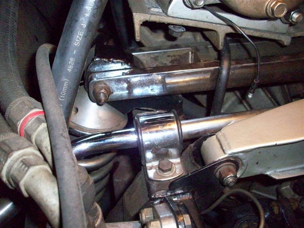
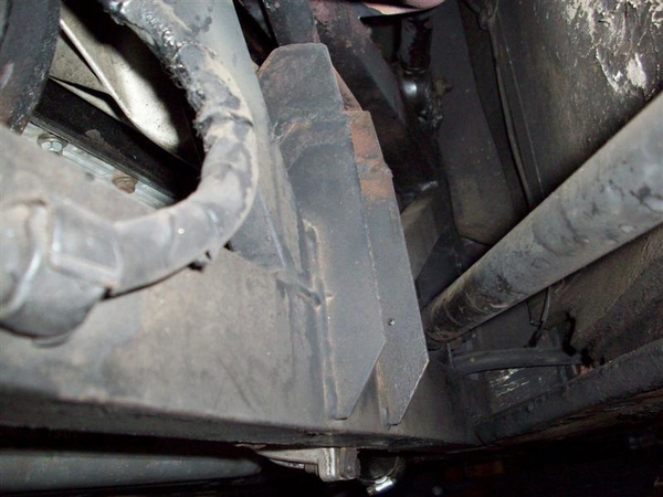
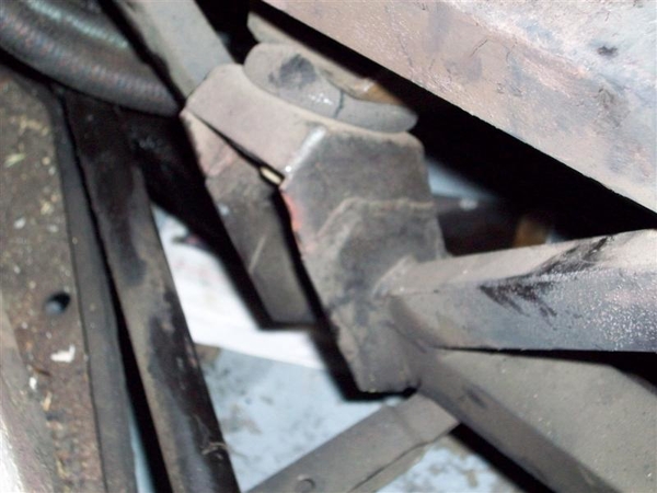
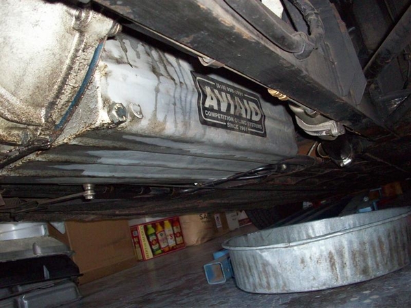
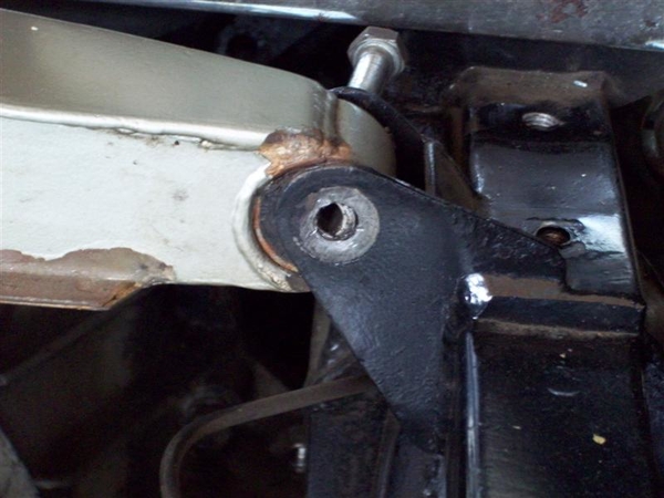
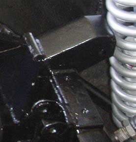
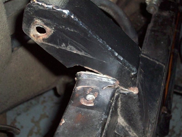
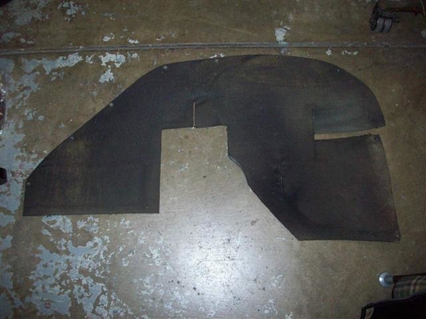
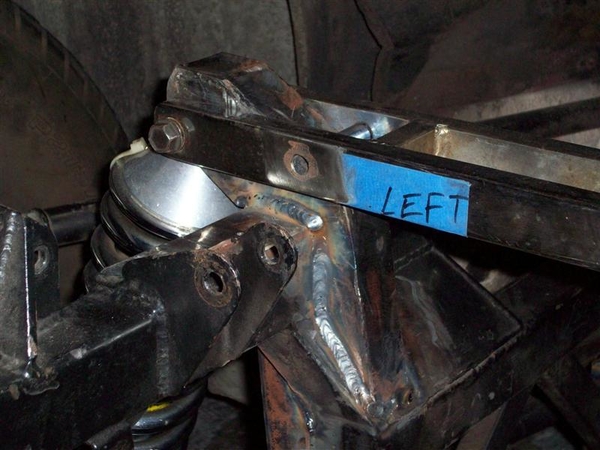
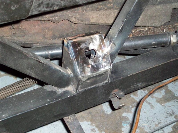
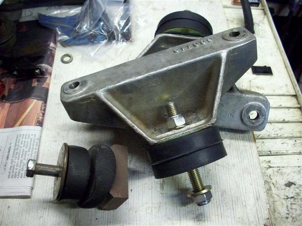
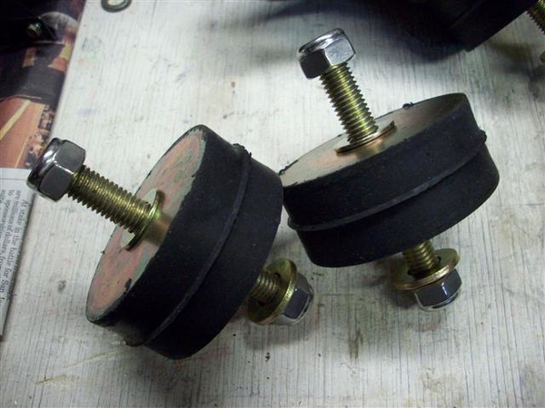
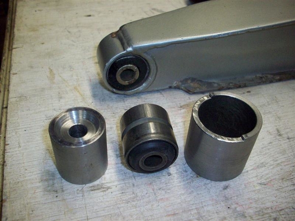
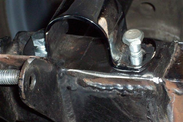
 This mirrors what the factory originally did on the RH side to make up for the notch in the frame to accommodate the shifter linkage.

While they were in there with the cutting and welding tools, the frame mounts for the engine were lowered back to the stock location!
 

Now, if I have room to raise the motor after I get it all installed....I will add shim plates under the mounts on the engine block!

Now I just need to get back on the motivation train to get it all rolling again!!!

Yesterday I did buy the silver paint I want to use on the chassis.... baby steps...baby steps!!!!

Steve

Attachments

Images (3)
  • blobid0
  • blobid1
  • blobid2
Last edited by mangusta
Hey Steve, I need to start off with this:

I have no interest - ever - of starting a Goose restoration of any sort whatsoever, however...

Your posts are just great. I read them all through, and man, what a job! Ingenious work, nice write ups, great pics, and an obvious passion. How could I STOP reading?!

Great going. Best wishes! Keep us posted on the work. That is one beautiful car, even half disassembled!
AH...
Thanks for the comments!

Yah, it does look so good just sitting there, it's tough to get back to work on it!!! Smiler

Will keep the updates coming as I get it back on the road! Can hardly wait!!! Have a lot to do but I've done most of it already once, so it is really old hat.....or at least that's what I'm telling myself!!!

Steve

Here is a classic example of why doing work on classic cars takes so darned much time!

(I haven't been working on the car much lately...have been multi-tasking it with a project in the backyard that includes new sprinkers getting dug in, and now I'm expanding our back patio area, so am leveling dirt, moving dirt, gonna shovel in sand, and lay in a few hundred square feet of stained pavers....have been busy and have a bunch to go!) ( I did order new motor mounts...! They are on their way!)

Out back, on the left and right sides of the engine, there are two "heat shields" (asbestos sorta stuff....) that are meant to keep heat off of the stuff in the LH luggage area, and on the other side, the gas tank.

Well, the one on my LH side is toast, and I have been meaning to replace it with something more modern with less or no asbestos content.

Since I have the engine out, this should be an easy job. I figured about an hour per side.... I ordered some "prime candidates" for materials, and a day or two back decided to jump in and pull the shield off and see how it is constructed and what I can do to rebuild it!

(There are before shots above somewhere....)

Here is a shot of the insulation pad and the heat shield removed from the wall of the engine compartment. Now keep in mind that I've already welded a canvas Eddie Bower bag to the inside carpet of the LH luggage area a few years back, so I know there are issues.....


Hole is not really obvious.

Removing the small 11ish x 14"ish asbestos pad reveals this!


Had not figured on this piece being so destroyed!!! (This is the same crap that DeT glued to the bottom of the gas tank and the insides of the doors and rear quarter areas. REMOVE THIS STUFF AT YOUR EARLIEST CONVENIENCE!!! It does nothing but trap moisture against the steel....and we know what that results in? Ferrous Oxide.....ugh!

Here is the other side of the heatshield, note the thru hole...this is the side that sits against the inner pad.


Here is what awaited me underneath the padding..... ya think those headers got warm? Smiler


I had not planned on refinishing the engine compartment walls.....!!! Not sure how much I want to do! It will NEVER end.....

Lastly here are the two products that I am considering. Both were procured from Aircraft Spruce. The stuff on the left "Fiberfrax" is what I want to use to recreate the asbestos stuff in the small shields. I was thinking of backing it up with a small piece of the stuff on the RH side "Cool It" that would be hidden from view.... It is two silver metallic sorta layers with a thin sandwich of yellow fiberglass sorta looking insulation in the middle.


I'm not real wild about using the Cool It for the engine compartment wall....not sure about the silver look.... Will see what some others have done and how they came out! Feedback is good folks..hint hint....

So here is how my "hour long job" (per side) has turned into a saga.... Now I need to source some flat head rivets, cuz the asbestos was held in place with rivets.... I need to source, pattern, and install padding before the shield, AND I need to clean, sand, and repaint the inner fender well before I can do either of the previous!!!! Double UGH!

I sure am glad this is one damned fine looking automobile!!!
Ciao!
Steve

Attachments

Images (5)
  • blobid0
  • blobid1
  • blobid2
  • blobid3
  • blobid4
Last edited by mangusta

New Motor mounts. Had to buy 12 to get 2....so will have a few extra sets to get rid of!!! Bought stainless nylock nuts, and hardened washers for backing up the nuts. 12MM studs, 1.185" (30MM) tall. 500lbs rating on each.


More later...


OK, it's later! (6-30-09) After digging into the material these mounts are constructed of, I found out that their temp rating is far lower than what I would feel comfortable using or selling to anyone else. Something like 140F, 160F max short term. Having a 195F-ish degree engine(core temp) and headers passing down about 4-6 inches away.....I don't think so. Am working on having these remade with something that is more like 240F tolerant plus much better resistance to oil and gas exposure.

Does anyone have a new original mount handy??? Even a toasted original may be good just to be sure that I am not chasing down a wild goose trail! Hah! These are 1-1/8" thick but I would just like to know how thick the originals were....

Anyone need some HD vibration isolators for some heavy equipment? I have some I can turn loose!!!

UPDATED 11-15-09 I have new nitrile rubber mounts now in stock...they look just like these, but are a better suited rubber for exposure to high heat, gas fumes, oil, and grease. See my posting in the Goose for sale forum for more info on purchasing a set of these!


Steve

Attachments

Images (2)
  • blobid0
  • blobid1
Last edited by mangusta

SMALL PROGRESS IS GOOD PROGRESS....RIGHT??

Went to Reno with POCA and had a blast, finished up my patio project so that I could throw a party for the wife's birthday....(and garner up some stock of brownie points!....) and am now ready to dive back into the Goose!

In between laying bricks and everything else, I managed to find some rivets that were close but not that close to the originals, and a rivet set (punch) to set the rivets with.

My dad sent me this from his garage....to mine.... I wanted something simple.....and while this is bigger than what I was thinking about, sure makes it simple to set rivets!!!


I bought some dies for the rivets, and he machined up some adapters to make them fit into this press. Works like a champ....once I clamp it to the bench...!

Here is my end result after bead blasting the heatshield frame and painting it "BBQ black" (flat black hi-temp) cuz I couldn't find any hi-temp semi-gloss black at Home Depot and I wasn't about to chase around looking for a can of paint for something that you can't see once the engine is in place!!! I had one spot next to a rivet where the tin had evaporated a tad, but as I said, not going to sweat this particular detail a whole lot!


Another bit that was needing servicing was the rubber bushings at either end of the trans cross member. A while back I had sent back some drawings to my dad, a retired machinist, and he made me up this pusher/holder affair to push old bushings out, and new in... What complicated matters was the fact that the resting surface on the crossmember is not flat due to welding during the construction process. This required putting a step in the holder.... Looks like it will work just fine, either side now. I'm not going to push my old bushings out just yet until I get all of the other pieces to fit properly, ie sway bar, ladder bar...


AND last but not least, I was missing the RH idler pulley stand for the engine/jackshaft idler....and Greg T., another local Goose owner working on a puzzle car, came by the other nite before the PCNC meeting to check out my car and take some reference pic's to aid him in getting his car back together! He brought by this pulley and stand-off assy and I'll spec it out, make a drawing, and have my dad whip out one of these for me! Sure is great to have local guys with cars that are apart!!! Smiler


NEXT! Make up a cardboard pattern, and cut out the LH heat shield for the firewall, sand down the old garpy paint, and get it coated with something high temp that will accept the adhesive backed temp shield that I got from Cool It. (Not the yellow stuff I initially bought) This stuff is called "Aluminized Heat Barrier- Adhesive Backed" and is about $55 for enough to do the left and right bulkhead/firewall areas. Sorta pricey, but made to mount near heat sources.... Everything else I have looked at just didn't wax my paint.....so to speak.

Plenty to do, but I figured I'd update the post!

Ciao!
Steve

Attachments

Images (4)
  • blobid0
  • blobid1
  • blobid2
  • blobid3
Last edited by mangusta
Quick note: Ferrari 308 and 308GT4 use that EXACT pulley and holder setup, along with the narrow belt for the smog pump. I will look and see about finding some, the (older) Ferrari community can be very helpful too. There is a multi-million dollar vintage Ferrari parts warehouse in Sacramento. I bought my Mangusta marker lights there for less than Mangusta (or Fiat) prices.

Jay
Last edited by jmm3

OK, take 2.....

Back on the Goose again, after about 10 weeks of little to no proper progress!

Spent some time looking into finding a new idler pulley standoff, for the front of the engine, but this turned out to be a "goose" chase...of sorts! Will have one made....

Worked on getting some new parking brake cables made up, but no luck finding the eyelets for the small 3mm cable! I found cable, sheathing, and ferrels that can be modified to fit, but no eyelets! My contact is still working with some old prints.... we'll see what happens..... May just end up brazing my old ends back on..... Frowner


Something completely different: rear disc brake kits for old Ford 8 & 9" rear ends....trying to reorder parts, but now instead of costing about $3 each, they want $6! Even when the quantity is for 400! I thought we were in a recession where shops were hungry for work?????

When my car was repaired, the work that was done looked fantastic! However, upon closer examination, and when I started bolting up the other parts that all reside in this "one ton of crap in a half ton truck" area of the frame, I ran into problems with things fitting.

A hole for the sway bar mounting clamp was drilled in the wrong location and needed to be relocated. Also, the upper shock mount portion of the repair looked fantastic, but it must have slipped position before it was welded into place, because in the end, it was crowding the other parts such that bolts would not fit properly into the other mounts, or wrenches no longer fit, or the bolts rubbed the sway bar worse than before.....and being the picky SOB that I tend to be sometimes, I just couldn't see slapping it together....cuz I know it would just bother me knowing it was there!!!

I think these cars are special, and deserve proper care and repair! So, I'm taking a little time and redoing it properly. I hope.

First, I carefully removed the repaired mount, using a thin Dremel wheel where possible, and thin hacksaw blades in the odd corners and finally got it off, preserving as much metal as I could.

I then cut off a bolt, and recessed it into the maligned hole, and tonite, welded it in place, filed it down flush, and drilled and tapped it. Came out very nice, and the sway bar clamp now sits where it should!


I still may have some interference with the sway bar and the bolt heads of the top ZF mount. I had this before....and I am thinking that I may make up some 1/2" spacers to put underneath these sway bar mounts, to lift the clamps up above the bolt heads. Would only require 1/2" longer bolts.....not a big deal. Will see when I put everything back in place......whether they will be needed or not.

I finally used my new bushing tools and pushed out the old upper ZF mount ends, and cleaned up any protruding welds with a file, cleaned and greased the holes, and pushed in the new bushings! Other than some resistance getting the old rusted ones out, a little PB Blaster helped loosen one stuck one up(!), the job went quite well and the custom tools worked as they should!

I used a 6ton bench top press to get the old bushings out. I used the same to push the bushing back in on one side, but on the other side I experimented with a large c-clamp and it installed the new bushing just fine! I was able to fine tune the fore-aft position of the bushing with the c-clamp very nicely!

Here is a shot of one new bushing in place. If the center looks off center, it is. I used these briefly in a set of factory shocks, found the shocks were bad, and pulled the shocks, took the bushings out and saved them for this job! They will settle back to center when weight is put on them.


Another project I've been toying with, is a means to support the upper frame sections, from side to side, to eliminate the flex that is allowed by the bushings in the ends of the upper ZF mount. As Dick Ruzzin pointed this out, and went on to re-engineer the entire mounting and ZF support system of his car with a very involved repair or implementation, it got me thinking. Here is my very simple solution to at least part of the problem.

This is a solid bar, that with longer bolts, should be a simple affair that will strengthen the top of the frame sections by tying them together and will limit their ability to move.


While it does nothing to strengthen the area where the upper a-arms attach to the bottoms of the top frame rails, it is a start. And it only weighs in at one pound!

I measured the ZF cross mount center to center hole dimension and drilled the same dimension into this bar. Your car may vary slightly from what is shown!!!! I had to put some weight on the wheels to get the bolts back in, as having them unloaded (wheels hanging) pulled the top of the frame outwards slightly making it impossible to put the bolts in.

I have some spacers to make yet so that this bar doesn't interfere with the two ZF bolts, and I will need slightly longer bolts at the ends to snug it in place. I will also contour the ends to remove the square ends... Most of this will never be seen if you carry a spare tire....

Next? Getting that upper shock mount tower put back onto the chassis! Stay tuned!

Attachments

Images (3)
  • blobid0
  • blobid1
  • blobid2
Last edited by mangusta

Add Reply

Post
×
×
×
×
Link copied to your clipboard.
×