[QUOTE]Originally posted by Mangusta:
I want to see what an allen headed nut is....!
Here's some (if the post works....)
Attachments
Images (1)


quote:Originally posted by Mangusta:
... My plan was to yank the heads which would allow my son and I to lift the remaining short block up onto an engine stand from where I could then remove the pan. Well, easier typed than done!
Rich,
If you have the time to put together a simple diagram, I would surely love to compare it to a couple of jackshafts up here that are still waiting to be installed! I missed an opportunity of another club member who installed his on Sunday! He was helping me on Saturday and hadn't known I was running into dimensional issues!! Ooops!
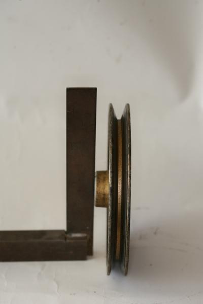
I'll put my pulleys back onto the shaft after I pull it all apart again, and see what the pulley center to center dimension is and go from there! It can't go back together the way it is.....
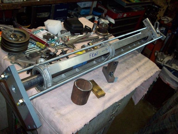
OK, just like Playboy wouldn't be the magazine that it is without pictures to go with the excellent stories, here are more pictures of what I have been rambling about!
Here is some catch up from two weeks back! ( A coupe of repeat pictures here.... oops!)
Pulling bearings from the shaft. Much discussion about whether these should be a slip fit or a press fit! Pulleys and nuts hold them in place..... OTC puller set purchased off of ebay, reasonable import stuff.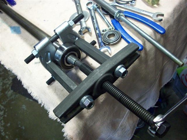
Here I'm pushing/pulling a bearing through the rear hole to burnish it a bit, and to make sure that they will go through! I pulled a bearing through each hole at least twice. Thin coat of anti-sieze was used.....that stuff gets on everything.....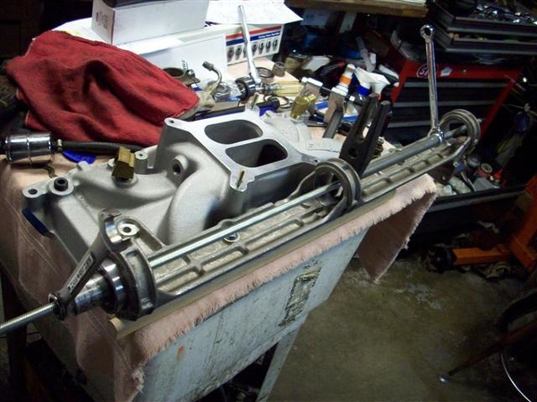
I had to be careful not to put TOO much pressure on the bearings as the jackshaft bracket would distort! So when ever possible I pulled from the center hole to the rear or the front...not the entire span front to rear.
I have not cut any short rod for doing this....but it would come in very handy!!! Long rod= lots of nut spinning! You can see a long piece of steel that I had left over from making my extra rear shock support attaching points, to take up space fast!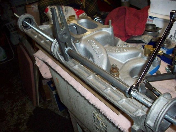
Here is a close up of the rear surface after the bearing has gone through twice. Once you get it moving, it goes just fine. Not a slip fit!!!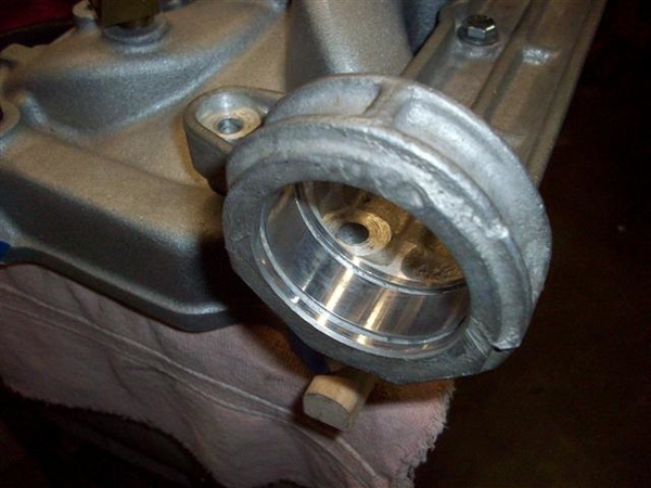
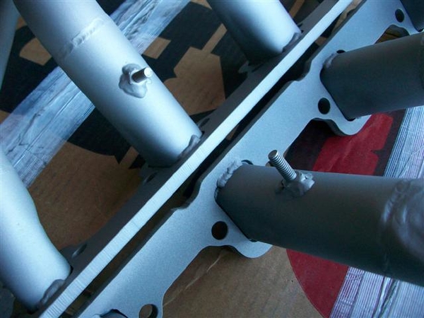
Here is a problem area for me! Hex bolts just are not optimum for the two rear bolts in my setup. The fronts aren't a great fit either! Now my shaft has been remade....so I have NO idea if the diameter is proper or not.....your mileage may vary!!!!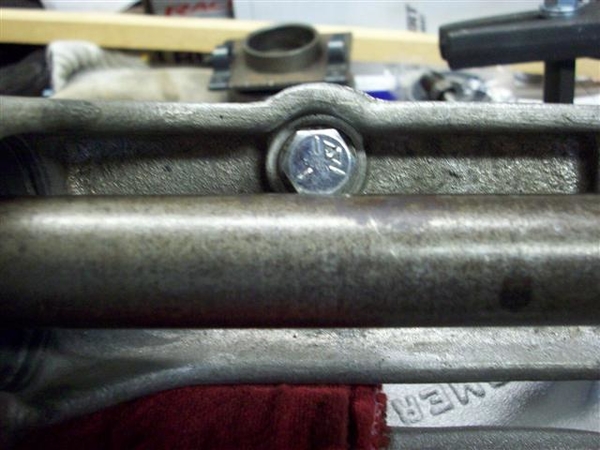
Here's what I mean! I'm switching to allen headed socket bolts. Not ideal but better. I will need to get a "long shank" 1/4" drive bit...short ones won't cut it!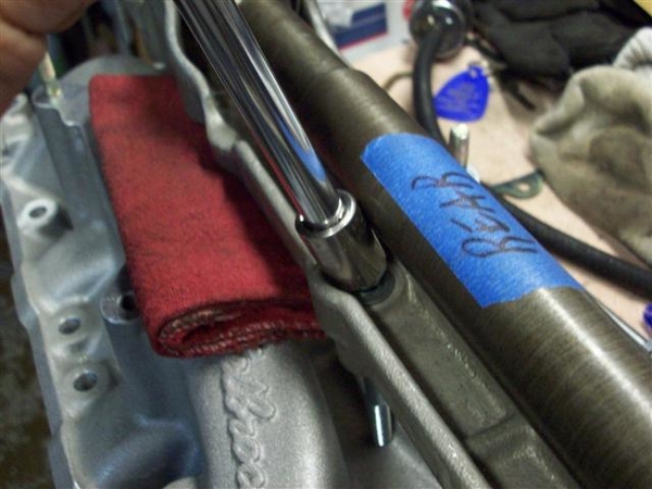
Here is my collection of misc bits and pieces that I had made up for pushing everything together. Note the pieces setting on top of the bracket, that I made from angle aluminum, to prevent the shaft bracket from bending under compression. They seemed to work....but it took a few sets of hands....tools are not finished yet.....to be one person things....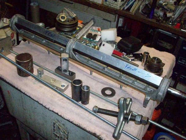
Closer view...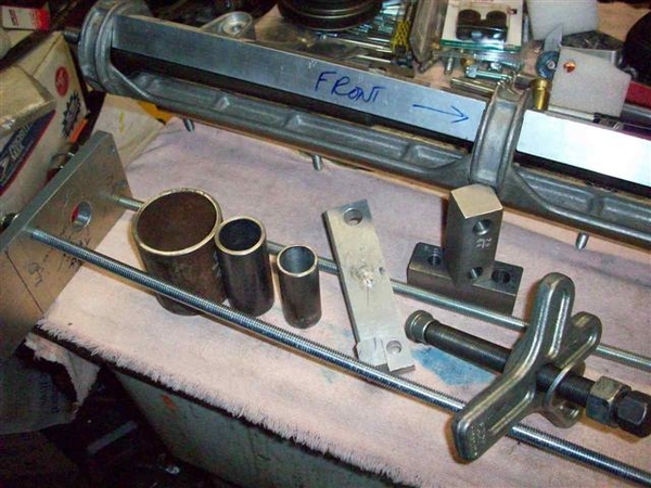
Large circular thing is for pulling rear bearing out. Circular thing in the middle is for pushing the rear bearing in, smaller circular thing is for pushing the front bearing in. Rectangular aluminum piece is for pushing on the circular things via the harmonic balancer puller. It needs a couple of holes drilled in it so that it will slip over the threaded rods when used for removing or installing... Pieces holding the jackshaft up are the drill blocks I had made up for dealing with my rocker arm stud holes. They worked great!!!
Front bearing installed. Note how it is just proud of the bracket! I think it needs to go in a tad....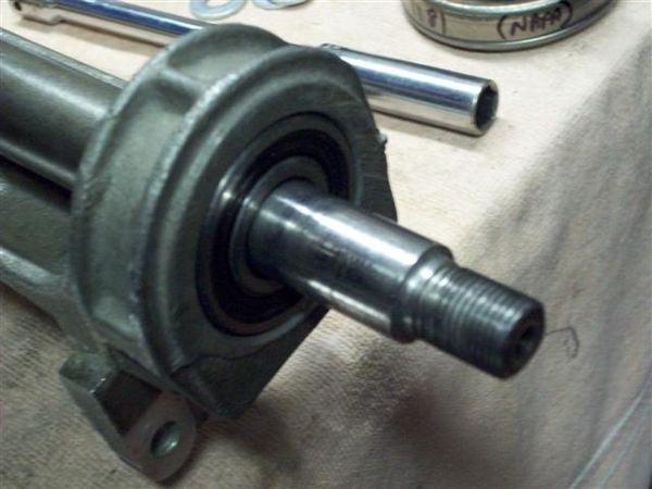
Rear bearing in place, snap rings installed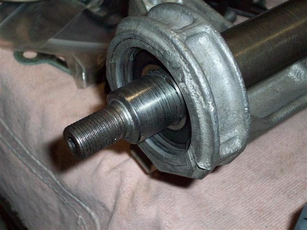
Center bearing removed...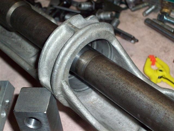
Here is are shots of the whole installer thing assembled.. It was good theory..... Would love to see what a good bearing shop uses!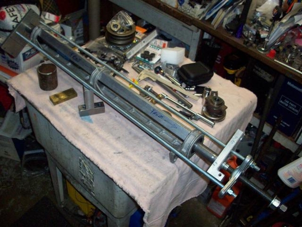
Front pulley installed. Note the amount that the shaft sticks out! Pulley is also hitting the bearing seal, so would need a small spacer which would push the pulley out more...yet it needs to go in about .125" to align with the water pump pulley! So I think push the bearing in 1/4" (cut shaft to fit...) use a 1/8" spacer behind the pulley to keep it off of the bearing seal....and should be great! Will need to revisit this dimension, as there is a recess in the back side of the pulley that will need to be accounted for.....also!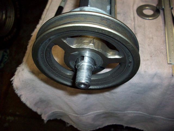
Another view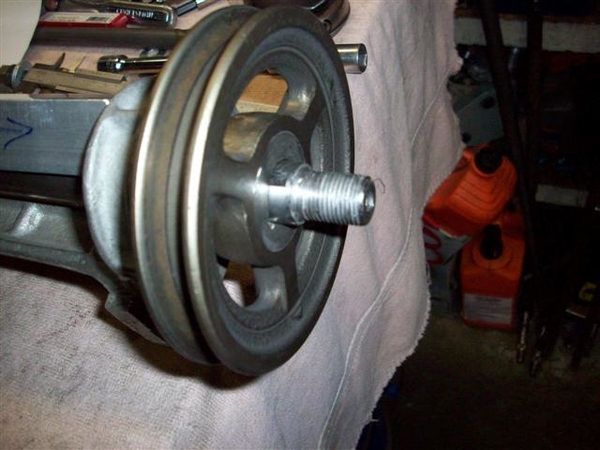
Outward facing sides of the pulleys and the various pieces I used to space and secure. Rear is on the left and front is on the right.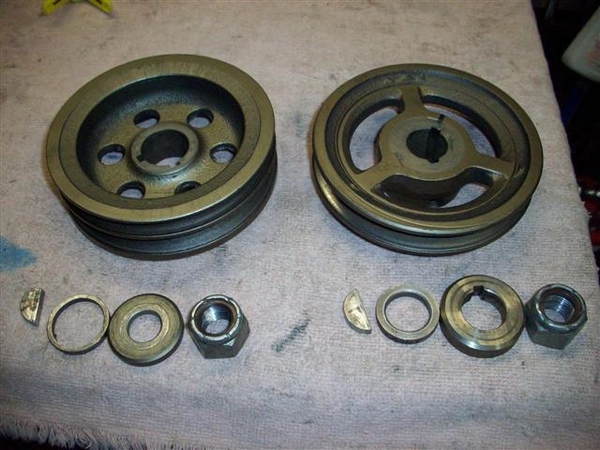
Inward facing sides of pulleys: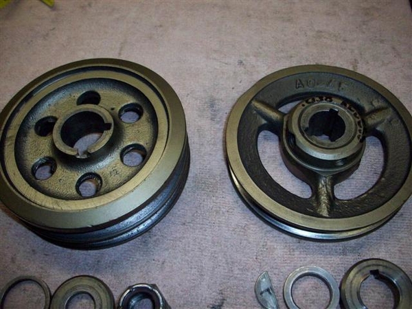
OK, next pictures are not for faint of heart!!!! Drilling on a mostly assembled long block.....!
Drill block in place, drill stop in place on drill bit. Worked nicely!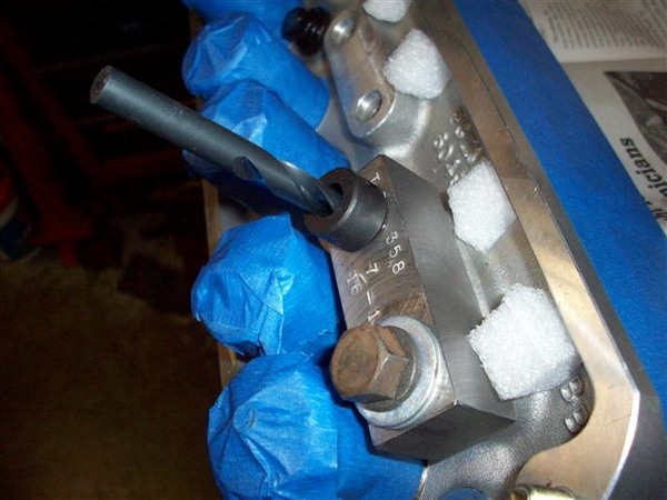
A bottoming tap, for getting more threads into a blind hole.. Note how the tip is not so pointy, as most of that point has been removed to allow the tap to go in the hole that 2 or so turns! Use solvent, WD-40, or even water when tapping aluminum to keep the tap from gumming up.....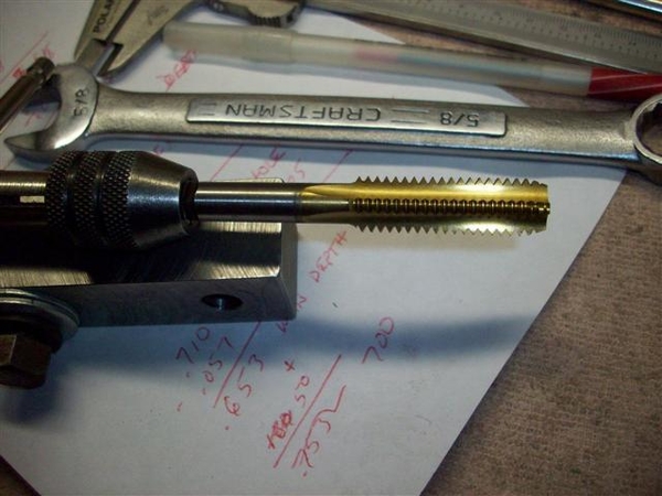
OK, enuf for me tonite! 16 holes are drilled and tapped.....on to push-rod guideplates again!
Steve


Well, this has been interesting!
For a bit, I was thinking that my shaft had been remanufactured to some odd dimensions......very odd....
Rich Chandler has been an immense resource to me here, in that he not only sketched out a rough but very detailed drawing of the jackshaft from his car, but he also dug out the pulleys, bearings, and attaching hardware and sent pictures of it all up to me! Oh, and he measured up the front pulley for me too!!! More on this later.....
In an effort to get some small stuff done, since big stuff is just not happening right now.... I took care of this....
I am using a late model 5.0 roller block, which has a provision for an oil dipstick in the side of the block about 3/4 of the way down the LH pan rail, to the rear. I used a 1/4" NPT (National Pipe Thread) tap and gave it a few whirls into the metal, and filled the hole with a brass plug I found in my junk, coated with some Permatex #2B Form-a-gasket (non hardening sealer).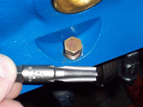
Since I was nearby, here is a shot of the drain hole boss that I had to take metal off of in order for the DeTomaso engine mount bracket would bolt up properly! Wasn't much, perhaps 1/8" of cast iron...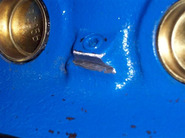
Next was the dipstick. Since I plugged the hole on the LH side of the block, (dipstick would run headlong into either the AC compressor or the coolant overflow tank...so opted for the stock location...
I am using a dipstick that came with the motor...found on many many many late model Mustangs, T-birds, Mark VII's etc. I cut the bottom section off of the tube first and filed down the sharp edges.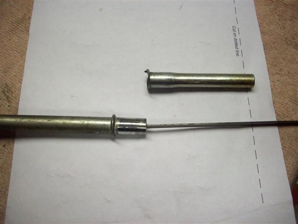
I then wiggled and forced it into the hole in my new timing cover....can't remember if this one came with a hole or I drilled it.....that's the problem with an engine build that spans years instead of weeks!!!!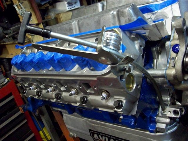
Using a crescent type wrench, I reformed the little mounting bracket on the tube and was able to get the metal to line up with a convenient 5/16" hole in the front of the head. Drilled a suitable hole in this little tab, cut off the excess and filed it all smooth....
Using a tubing bender I have I managed to put a slightly different bend on the main tube...not much....and also I dimpled the hell out of the bottom of the tube, where the retaining guide wasn't fitting the tube real well.....oops! Can't see it when it is installed anyway......just little dimples....little bends!
Dipstick still moves in and out "ok" but it is dry and will be better once oil is involved!
Here is a shot from the business end...what you will see when looking in the engine bay....I hope!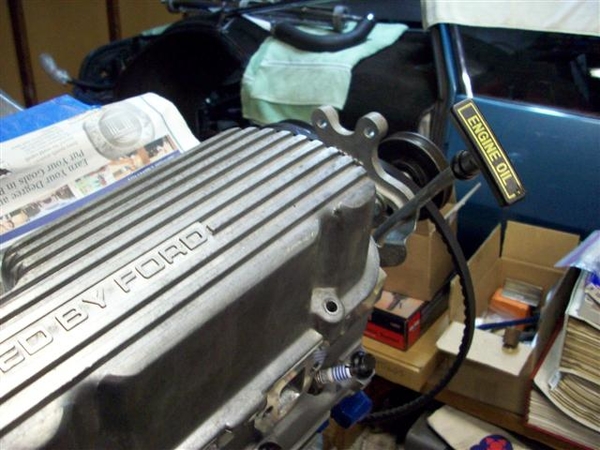
I also installed the one unique main stud that I need for supporting the Aviaad oil pan pickup. I didn't have this piece when I installed the crank etc. Sorry, no pic's yet.... And I put the oil pan up under the engine hanging by two bolts. Will button that up once I am done making a mess out of the rest of things up top! It goes on once the top end is all sealed up!
OK, while chasing bolts or something or other, I happened to come across a little adapter that I knew I had seen...but couldn't find! Was driving me nuts!!! I knew I got this in a water pump that we bought for our 68 XR7.....I thought I threw it in my steel bucket of nuts and bolts, but alas, I found it one shelf up in my brass recycling bits!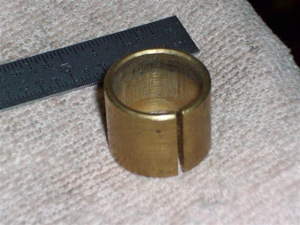
THIS is the part that adapts the DeTomaso water pump pulley's larger diameter center hole to the water pump center shaft, to keep it centered!!! The four mounting bolts won't necessarily do this on their own, although you could get lucky like I had been doing......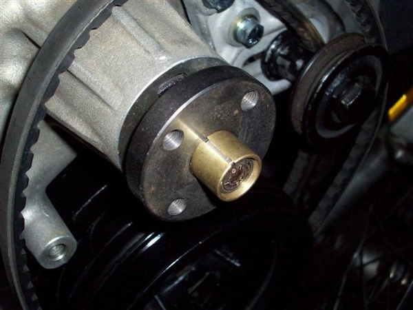
Pulley on!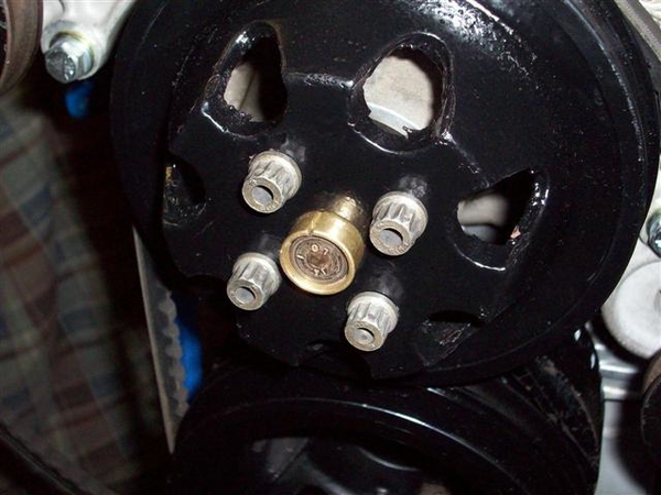


Back to my jackshaft pulley story!
I was just about to take the jackshaft apart again, and decided to check out some dimensions, since Rich has been so good to send them up! Turns out that they were all very very close! Over all length was just slightly different, but not too bad! So, I decided to play around with the pulley and see where I was... What I was up against was what you saw in the pictures a couple posts up, where the pulley stuck out too far unless I removed the spacers, which put the hub of the pulley into the seal of the bearing, as the pulley has a recess vs a protrusion.... It also has two holes drilled in it for set screws...told you this was an industrial pulley!!! If I cut the protrusion down to fit, I think it would cut into the set screw areas, so it either all comes off and I make a bigger spacer, OR, I do the RIGHT thing and get a pulley that is closer to the stock one!
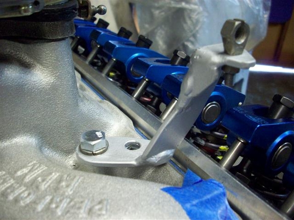
Here are a couple shots of Rich's pulley!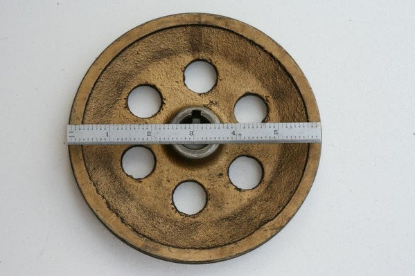
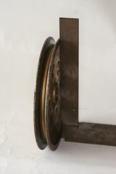
Here's what I figure happened many moons ago...about 1974 or so... When the third owner installed the Boss 302, they raised the engine frame mounts to allow the headers to clear the frame rails! When they raised them 1.5" this raised the original 6" diameter pulley into the body just below the cabin rear window! SO, they grabbed their industrial A/C supply catalog and ordered up a 4.5" pulley and cut it to fit..... Where the original is now, is anybody's guess, but I will tell you it WAS in Fresno....back then. (Still have not found the third owner.....who did all this work!) I did find the 4th owner and the jackshaft bracket and an air cleaner, but he didn't offer up any pulleys....I guess I could call and check anyway, but I think all he got from the salesman was an extra unused piston....!
So tonite, instead of working on stuff, I surfed and learned all about grey cast iron, ductile cast iron, maximum distance per minute of pulley travel....and that the internet is full of all sorts of crap!
Grey iron will work well up to about 4000rpms, ductile iron up to 6500. I believe these are continuous operational numbers, and that they would flash higher....but not 100% on that.... Ductile iron has more nodular metal in it, like cranks and rods.... Blocks and stationary stuff is made from the grey iron which has more graphite in it.... Told you...!
So, I just may contact a pulley manufacturer and see what it would take to cut one out of some billet steel.......Give them the dimensions and let them roll..... not sure if my dad would take this one on!!! We'll see!!!
Here is one last shot for tonight. There was talk of "allen headed nuts" and such before, used in retaining the jackshaft bracket to the engine. Here is a shot of one of Rich's fasteners....appears to be made from a 12mm diam socket head cap screw, that was drilled and tapped for 5/16"-18 about 3/4" deep! It is meant to be used with a double sided stud, as was used on the intake's center 4 holes (Two on each side) in the stock config from Ford. He says that they do not fit tight into the bores of the holes in the bracket, so there is still room for the bracket to move around a bit. They do not act as locators...
I thought it was a pretty neat deal! Have some pic's from another crazy Goose owner that came up with a rather novel aproach at this whole deal too!!! Will post later....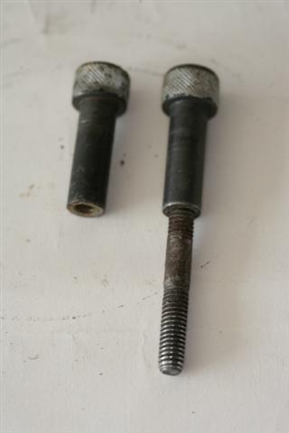
Out!
Steve


While the goose chase for a front pulley continues...progress today on more small stuff! Sheesh! So much small stuff!!!!
Called on new valve covers...that hadn't arrived while I was gone.... had been on back order from Ford, arrived at Rousch yesterday and shipped out today after the phone call to say "yes I still want the stinking valve covers!!" ![]()
Hit some shops and picked up more stuff...
HD vacuum hose and another 1/2" hose barb for the PCV line to connect to the rear of the intake.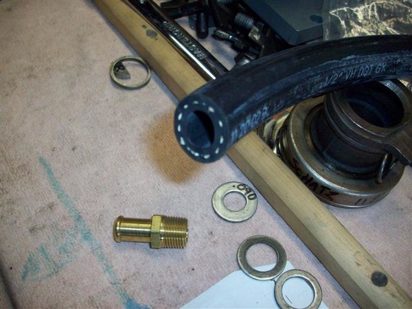
This stuff is HEAVY walled and shouldn't collapse. I had been using standard heater hose and it was looking like it had collapsed or had potential to do so...... This piece will feed the brake system, so no goofing around here!
Stopped by my clutch guy and bounced some things off of him....namely clearance on the pilot bushing. Mine was looking a tad galled, but I believe I had the clearance set a little tight. Shaft is .5904"ish in diameter so went towards .5940" on the lathe. Was a little tricky setting up a used piece in the lathe...but with a little talent helping me out, it came out great!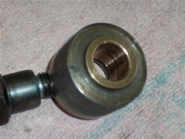
It was either take a light cut on this, or machine a completely new oillite insert....
Also tried to get a new (BCA 1625?) throw-out bearing but both my clutch guy and the other place I picked up my hose at were out! Ordered one....
Also got some small copper washers for the clutch and brake fittings...."just in case!" Worst case they are spares....they don't take up much room in the tool box!
While I was out, my bearings arrived from Giardi Bearing, for the idler pulleys.
This is what I took out of the idlers (new bearings on the left):
The bearing I took out was a 6003 which is too narrow. To take up the space, the PM (previous mechanic) used snap rings to take up the slack! I had pulled the bearing out and replaced them with the same...and put the snap rings back in.... Since I have learned so much about bearings....I looked into a larger (wider) size and sure enough, a #63003 2RS1 was available! Ordered three so that I had a spare...just in case... "they're small!" Pricey little buggers!! Ran me just over $30 each! ...but they did deliver to my door!!!
Used my assortment of sockets and such to press the old ones out, cleaned out the dirt, lubed with anti-seize and pressed the new bearing back in place, reinstalled the snap ring...like new!!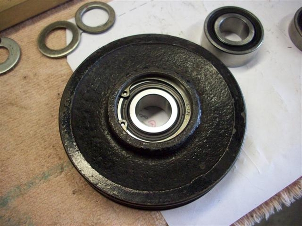
Mounted both idlers back up to the mounts and confirmed proper line up. Had to work on the bolt for one side as it didn't move in and out of the bearing easy enough for my tastes, so just dressed it with a file and polished it up with some worn 320 wet/dry sand paper.
Back to the Sharks game! Tied up, overtime!
Ciao!
Steve


Osofast,
I checked out those pulleys and at 5lbs for a 6" pulley, that is one lot of mass! I didn't see a V-belt on that page, but didn't get too far either....thanks for the idea though!
I've checked around a bit and it seems that machining something out of steel or T6061 aluminum wouldn't be all that difficult, just time consuming....
OK, back to the Goose chase!!!
Progress today in the spinterogino dept. (distributor!)
I needed to change the gear from a standard cast iron gear (marked with orange paint), good for regular flat tappet cams, to a steel gear (marked with NO paint!), compatible with roller cams.... I had previously pulled the gear off using my small press.
Getting the new gear installed wasn't going to be easy... (so what else is new??? ![]()
)
I tried this Sunday: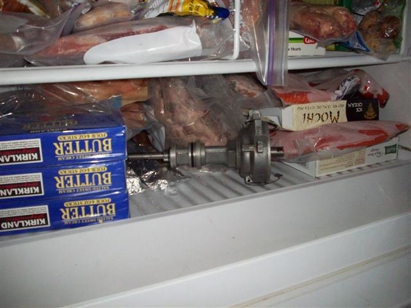
and this: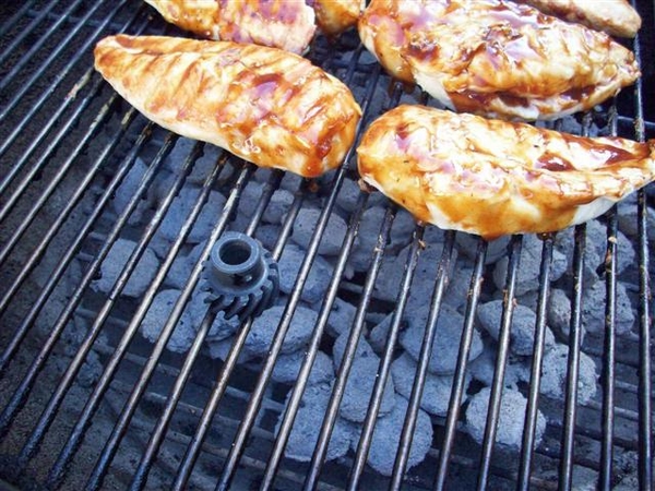
But it didn't work. Was still a press fit. Since dinner was ready... ![]()
.... I gave it a rest until I could get back at it today.
I had already guestimated and drilled one hole in my new gear at what I had thought was the proper location, based upon the hole in the gear I removed.. Recommended way to do it is to install new gear and drill a new hole thru gear and shaft and install roll pin... Well, who am I to do it the easy way....?
My guestimation proved off by .050" once I found the spec in the book!
So I pushed the gear off again using a tool that I got in an auction or such...somewhere, probably a Ford dealership...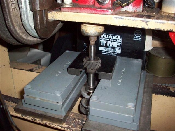
Note that this is the recommended way to remove the gear. Note the little 1/4" stub (in this case one of those little sockets from a multi-bit driver set that I found somewhere....) sticking in the end of the distributor to press against. You can also use a piece of an old distributor drive shaft to either press against or hammer against, but you need to support the gear by the body of the gear and not by the teeth!
Here is the tool and gear: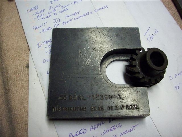
The proper measurement for the distributor is .024" between the little (upper) collar and the body, seen to the left of the gear more "up" on the shaft... Mine was at .025" and I'm not going to redrill a hole for .001"...sorry!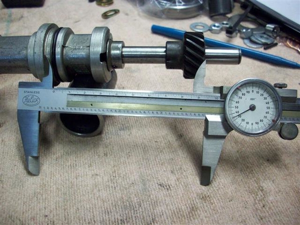
However, the other measurement, from the distributor mounting flange (above the o-ring) to the bottom of the gear, is supposed to be 4.031-4.038" to align properly with the cam gear. I was off by .050" so that was not insignificant...
After polishing the shaft a bit, putting some oil on it, and pushing the gear on in a new spot, it went on nice and easy...but easy in terms of putting it on with a press! It took a few ups and downs....pushing it on...too far...pulling it back off a tad, until I settled on 4.035" or darned close to it!
I then drilled the hole in the gear using measurements and marks I had made and came out dead nuts where I wanted to be. Started with a 3/32" bit and once through one side of the gear, and knowing that the hole was lined up, I carefully used the 1/8" bit to drill the starting side, go thru the shaft, and then drill the other side of the gear. It worked for me, your mileage may vary!
Tapped the roll pin back in place! Bottom is done. Now to the topside!
This distributor was originally for a 1979ish Ford. During these years the 302's were very low compression pigs. As a result, the engineers could get away with running HUGE advance numbers. I found the tower in this one allowed 21 or 16 degrees. It was configured to the 21 degree location... When multiplied by 2 to get crank degrees, that comes out to a whopping 42 degrees of spark advance!
In discussions with the local Mustang shop who are familiar with this engine setup and compression ratio, they recommended 34-36 degrees total advance period, which is pretty much in line what I had been using previously with the Boss 302.
In my pile of parts, I found another DuraSpark tower that had slots of 13/18. I went with the 13, as 13x2=26, plus 8-10 degrees of initial timing would net me 34-36 degrees total advance. If I feel I could use more, I can simply advance the timing up to 12-16 degrees. Keep in mind that the DuraSpark II module has a retard feature during cranking that moves the timing curve back by 10 degrees to make starting easier! I like it!
Here is a shot of the new (old) tower installed and the one I took out is to the right.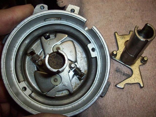
The actual curve would need to be set up on a machine, but from the feel of the spring settings, this should be close! All in (full advance) by 2000-2500 rpm's! A quick check with the timing light will confirm or deny this...
I put all the pickup and stator parts back in the top of the distributor. Checked the pickup with an ohm-meter and found 600ohms. Spec is 400-800ohms for a good pickup module! Cool!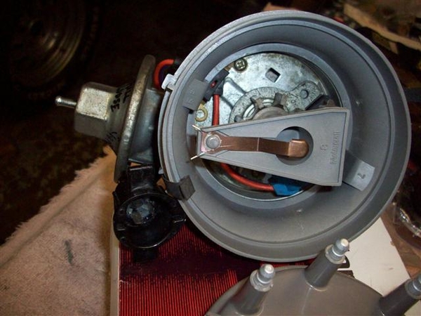
Backed the vacuume advance unit to "loose" but I do not plan on connecting it....at this time.
New rotor, cap adapter, and cap, and we are ready to roll! New wires are still in the box waiting.....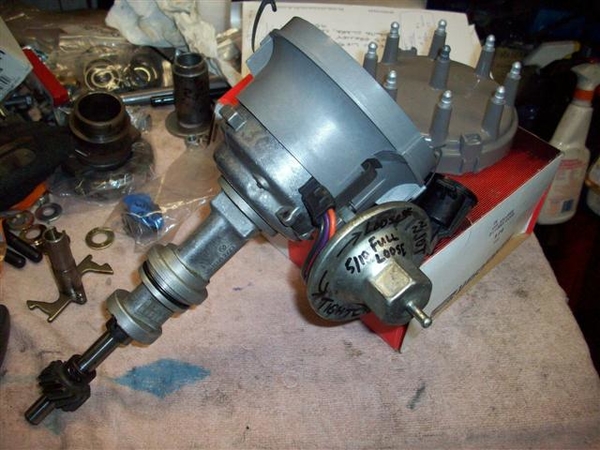
Putzed around with the new bottoming tap I received and finished up the one hole in the rocker arm mounts that I was installing a heli-coil in. This allowed the thread insert to wind further into the hole without drilling a super deep hole into the head.
Fitted one guide plate a little better to the stud and loosely installed the rest of the studs and guide plates.
Adjustment of rockers and guide plates is next, but not tonight!
Ciao!
Steve


Well, back from a great time in Reno! Passed lakes in the mountains still covered with ice!! Not so much ice on the way home though....5 days later!
One lone Mangusta showed up, so needless to say, I checked it out fairly well. Early car, #606, has a very unique "in-dash" AC unit as well as early round top side marker lamps. Was a conversion to an Edelbrock F4B many moons ago....as well as a set of Hall headers and cherry-bomb mufflers. Very sharp looking in red with black interior, took home the "most stock" award I believe. Only real noticeable deviation from stock is a set of aftermarket wheels. (Which the owner would love to replace with a set of stockers!)
Since returning home, not much progress on the Goose. Met with another local Goose owner, who lent me his jackshaft assy and pulleys to check out on my engine. His jackshaft bracket is an early version, with an extra mounting bolt in one of the center positions. If you look at the later ones, you will see a round area just behind the center bearing area where this was...
This version also had all three bearings held in place with snap rings, unlike the later version that I now have, where the front bearing is allowed to float.
I did pick up the new BCA1625 throw out bearing. Mine was new not that many miles ago...but since I'm in here, I'd rather spend the $30 and do it once! The old one can go in the tool box as a spare in case anyone needs one out on the road! I need to install it on the holder/carrier sleeve yet.
Have been a bit busy as I have detoured on a family car project.....getting the old family taxi running again. Blew a head gasket out of the blue....with only about 50-60K on it! (Replacement engine for the car...)
Here's a shot of what I've spent the last weekend and week nights doing!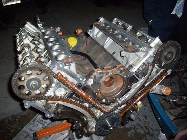
Our son wants to head down to Monterey this fall to finish his business classes for college, but the idea of taking a pristine 68 XR7 Cougar down there isn't sitting well with him or the previous owner (me!)..... I remember driving a nice 62 Impala SS to college, only to return it home 3 months later due to numerous break-ins and attempts, getting hassled by the cops for out of state plates......not to mention driving it in the salt...!!!
So, the idea is to see if the new head gaskets hold up....and squeeze another 50-60K out of it! Should be ready for the scrapper after that!!! This is a late 97 4.6L SOHC engine that will go back into our 92 Touring Edition Crown Vic. Cleaned up all the surfaces, checked the #8 rod bearing for wear, found little to none, so it's getting 5 qts of fresh oil, a new filter for a few hundred miles, then another new filter and 1 qt of oil and it should be good to go!!! This picture was early last night, but later it had the front timing chain cover, oil pan, and valve covers on it. Tonight it got exhaust manifolds, intake manifold and most of the wiring. I don't have a metric 12mm harmonic balancer installer, so ordered up a special long bolt from Fastenal today and will turn it into an installer.....! But will need to finish that in the car as fully threaded bolts are not in stock anywhere around here! I believe it is coming from IL.... BUT, the important thing is that I can drop the motor in one of these evenings and then spend the weekend buttoning every thing up and plugging all of the wiring back in! Then one more project will be off my list, and back to the Goose!!!!!
OK, now for some GREAT news! While in Reno, I happened to ask Steve Wilkinson if he had any Mangusta front jackshaft pulleys.....he replied that he thought he had two of them! Called him up last Tues or Wed, and sure enough, he had two on the shelf! One had some brazing on the backside....and one looked like new... "I'll take the latter please...!"
Here is what showed up today!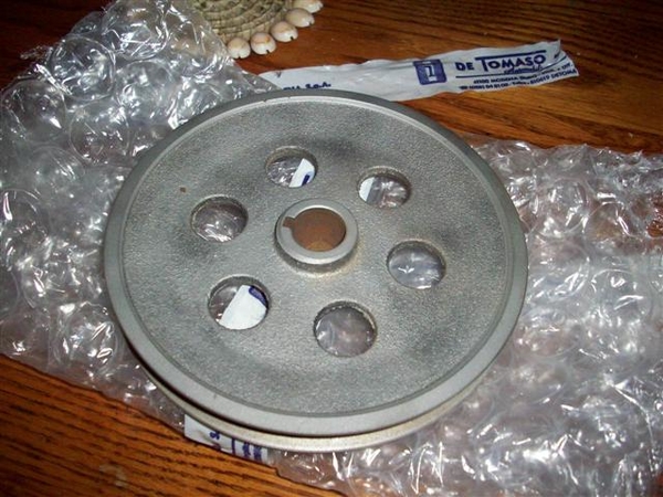
It fits my shaft just fine, but I still need to deal with getting the bearings to fit a little better!!! A couple hours on a lathe and I should be good to go....make a few spacers and then start torquing down an intake manifold!!!
I think after that, it is carb and fuel line work to do, fab up some sort of throttle cable bracket, and then work on dropping the engine back into the car!!!!! WHOO HOOO!!!!
Steve


quote:one looked like new... "I'll take the latter please...!"

Progress, digress.....story of this project!!!
Finally got my jackshaft in the neighbor's metal lathe and trimmed up the front nose so the front pulley will line up. Removed a step in the middle bearing area and cleaned up all three bearing areas so that the bearings slid on with a firm grip but no malletizing required!
Installed the front and middle bearings, but when the shaft was installed, the rear bearing hole was far from centered on the shaft! This bracket is anything but straight! I worked on it a while with a rubber mallet but was unable to influence the shaft to center much better...need a bigger hammer....but I resolved myself to simply run the front and rear bearings for now.
The only way I could figure to fix it would be to press or malletize the bracket so that the shaft bearings line up properly. THEN, machine the 4 mounting bosses flat..... I'll take that on next time the bearings go out.....in 20-30K miles.....! I'll probably regret this decision then....but I need to move on.
I had been working on rough drawings of a new throttle cable bracket...one of those "oh crap I forgot all about that part" things that you encounter once the engine is nestled away in the engine bay, your buddies are all standing around drinking your beer, waiting to "fire this bad boy up"....but you don't have a throttle cable bracket...because the old one doesn't fit!!!
Old one (slightly cut up....was into the process before I got the camera out....)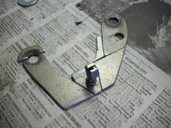
Here is my jig for setting up where I needed the new bracket to hold the little cable retainer: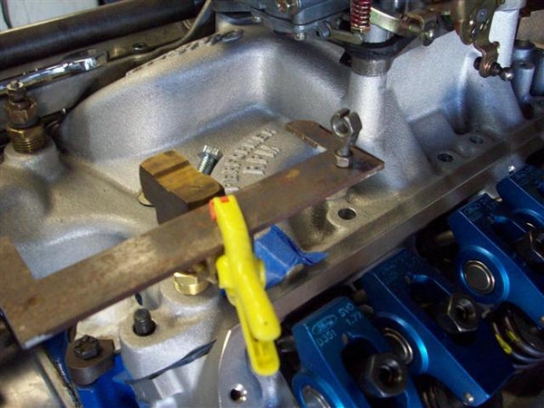
After lots of work with a hacksaw and hand files, here is the final result!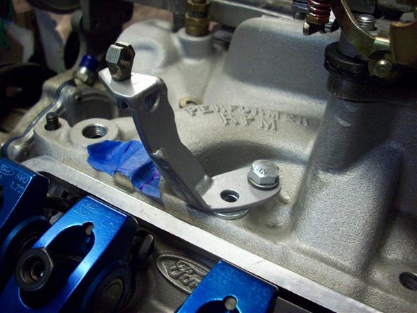
Also hit the parts store yesterday for belts and hoses. Brought 4 belts home and got one good fit, one "work in an emergency fit" for the water pump/idler belt. Struck out on the jackshaft belt...but know what I need now.... I will post numbers in the TECH section once I finalize them.
Also struck out on the hoses for the water pump to the lower metal tubes (to the front of the car) and for the "Y" pipe to the lower hose. See my post for info in the Tech Section of this forum. I looked through their entire stock (not fully stocked....) and came up empty. I know I did this last time and came out a winner..... Oh well, those will be some of the last things connected...so have some time.......
Today? Not sure...maybe install the intake manifold.....! I think I'm almost done modifying it!!!
Have a great 4th!!!!
Steve


July 5th....back to the parts store to check out belts....that only took two trips....second belt for the jackshaft pulley was still too small...so called and different sales clerk found me one in between...but this now the smallest increment available....no smaller ones or larger by just a smidge! (OK, at least in their system....)
Ended up with a Gates 13A1230 #9485 (13mm wide, A-type groove, and 1230mm long)
It fits OK, but the adjuster is out towards it's edge. The 13A1220 just wouldn't go on....but then I didn't get postal on it either....! It will work.
With no more to actually do to the intake, jackshaft, and upper end of the heads and block, it was time to install the intake! Cleaned up the gasket surfaces of finger prints and any dusty bits, applied cork end seals to block (double sided tape on them!) set the special Felpro gaskets (for the SVO heads) down and applied sealer (the Right Stuff) in the corners.... Lubed up all of the fasteners with anti-sieze and went to town on the intake!
First thing that pops up, is the fact that you cannot, no how, no way, with the tools that I have at hand, and that's a pile of them, can I get to the center two intake bolts to torque them down!!! The jackshaft bracket just gets in the way of making this a reality!! So I tightened them down a bit without the jackshaft bracket in place, then put the bracket on, tightened the rest down to spec, tried to get a wrench in to torque them some more...eventually removed one rocker arm to get some swing on the wrench....but it was faster to remove the jackshaft support, torque the middle two bolts down, then put the bracket BACK on and torque everything back down again........ I finally got it to the point where the gaskets were compressed, and the tightness of the bolts were at spec....what I ball buster mentally! "Is it gonna leak now?" Of course not.....
With the top end on, it was time for the oil pan. No more opportunities to pull stuff out of the engine if it gets dropped inside! I am using one of the whippy dippy one piece silicon pan gaskets that another club member gave me, as his project went from a 302 to a 351...... Thank-you very much, it fit fantastic! A little of the sealer in the corners, set it in place, and where the hell are the pan bolts???? Found a new set....oh crap, only 4 bolts fit! They're for an FE Ford.....back to the bolt buckets/boxes.....found a set of stock ones...... Installed them...but short one small one!!! Back to the box of "Ford" bolts....problem solved...pan is good-n-tight! I really like the one piece thing, being silicon, they installed little shims around the bolt holes, so that you cannot over tighten the gasket and squish it out! We'll see how she holds up after some miles!!!!
Installed the new dipstick tube, and for grins, dropped in the distributor. Looking like an engine finally! (Distributor will need to come back out for priming the oiling system. ) Also installed various fittings for water/heater with sealer, vacuum fittings...getting the small things out of the way!
Time to start dealing with carb fitment. Have a couple of slightly used Holley carbs, a 570 Street Avenger, which I believe will be fine, but I believe it will leave some performance on the table...so may opt for another 650 that I have set aside. The 570 was jetted very small on the primaries with #54 in them and a pair of 65's out back.....I bumped that up to a 65 primary and 72 secondary. (Ford ran a 66/71 combo in the 1968 GT350, which was a mile motor, so we should be close!) It should not run lean. 8.5 power valve....which may need to go down in value if the cam turns out to not have good idle vacuum. Used re-usable carb gaskets to make that task easier.......should I need it.
The 650 turned out to be jetted much bigger, at a 67/73, so would have worked ...but just a tad rich perhaps......all would depend on what the larger venturis permit in terms of fuel "mixture".
Started bending up fuel line for the pump to the top of the engine....but want to see if a local shop can do "double flare" joints in tubing... if yes, then easy cheesy! If not, then it's grunt and groan with the hand flaring tool....ugh!
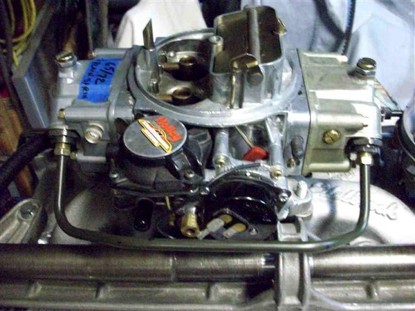
Here is a shot showing the fuel line, as yet untrimmed to merge with whatever I make to drop down out of the carb....I should have backed off a bit....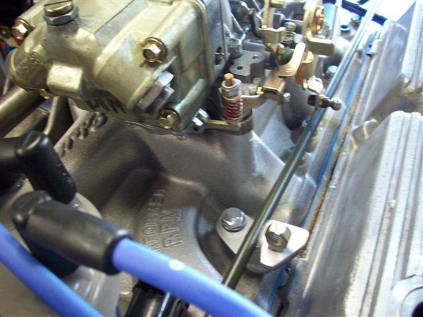
Tuesday night was carb puttering...ordered carb fittings for 5/16" line. 3/8" line is just tooooo big for such a little motor....
Last night: header puttering.....two sets of aftermarket header and neither pair fits well. I am guessing that I have two sets of Hall "big bore" Goose headers.
One set (silver in the pic) has doinks on the front most tube where it looks like the top bar of the LH suspension hit it...second tube may have a mark too....that cannot be good. At least you can get all the bolts in! I may chop out a section of tubing and re-route it ever so slightly.....if I can find some tubing.....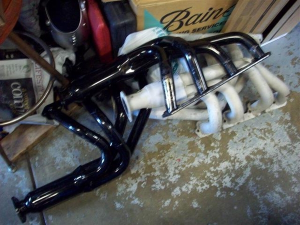
The second set, black in the picture, turned up with one having been installed and actually run, and the other was a virgin....never seen a bolt or carbon trace in it's life yet..... I can see why! There is NO way in hell that you could get a header bolt, or nut if using studs, to fit given the way that the tubing was welded in place.....not gonna happen!
Idea is to see if both headers fit to the muffler at the same point in space. I will then send the best fitting set off to get either Jet-Hot coated or alumi-coated....one is mo' better...gotta look it up.... then install the other set to drive around with until the headers come back from the coater!
Picture isn't too hot, but you can get an idea of the angle that it was coming off of the flange.....
After spending a couple of hours on the pair, I got them to the point that I can get a 1" header bolt in without too much difficulty, but more importantly, I can get a wrench on the bolt heads now!!!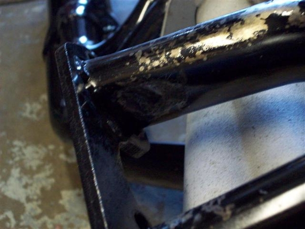
One side had at least 3 spots that needed malletizing, the other at least two....they were just a horrible job done.....!
Fast forward to tonight, July 8th.
Tonight I put the new bowl fittings in and buttoned up the carb. Checked things out, blew out the passages....
I installed the spark plug wires.....which turned out to be a BREEZE!!! Turns out the spark plug wires are numbered.... well duh! That sure took all of the fun out of it!!!! This is a late model firing order, so it is the same as a 351. 1,3,7,2,6,5,4,8 I do need to drum up some 9mm wire separators/retainers.......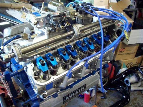
Here is something else I knocked off of the list.....something that few of you probably think of...but after reading a couple of recent posts from guys about problems with the ZF's in their Panteras, AND because it is so stinking simple..... there is no excuse... Lube the pivots on your ZF throwout bearing shaft! A half shot of grease should be plenty, wipe off the excess.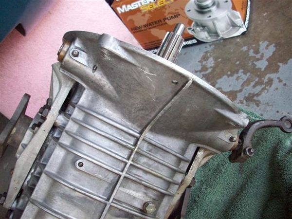
This is the bottom view of the ZF....in a Goose!
A LAST chore for me, is to machine down my T-stat adapter to 1/8" thick from 3/8". Turns out that the 90 degree heater bypass hose gets too close to one of the lock nuts on the jackshaft bracket where it attaches to the front idler bracket. Last thing I want is a blown $5 hose because it rubbed through on the $1 nut..... I was just going to put another hose clamp around it....but decided to go the longer road....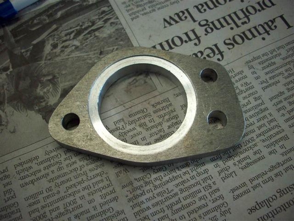
I believe that I can run stock Ford bolts to hold this together, with two gaskets...and the shorter spacer may allow easier wrench/finger access too!
I also had to file down a boss for a timing pickup that the late model replacement timing cover has on it. It appeared toooo close to the lower water pump hose that will be drawing water from the front....radiator. Again, I didn't want anything chafing, so filed the sharp edges off, reduced it's height/length, and polished it up a bit to smooth things......nothing sharp......!
So now my shopping list is FINALLY growing smaller....
30W break-in oil....12 qts should be enough for break-in and first oil change. After that, we move back to Mobil1 either 10-30 or 20-50.....
Fuel line to make "crossover" line to feed rear bowl.
Hose- to connect y-pipe to chassis tube. Still haven't had a chance to try a different store to check it out......
Also, header bolts ( I have a stash, but they are all used, and I don't want to risk buggering up the aluminum threads.....new bolts "should" be clean!) 1-1/4" long studs for valve cover mounting, some nylock-flanged nuts, and perhaps some nylon flat washers (good to 350 degrees!) to seal up the holes in the valve covers when tightened!
Just remembered one more thing! I want to replace the short straight junctions of rubber hose up front to the water tubes, with Gates Green Stripe super duper hose! Need to do that before the engine goes in.... I guess I don't have to...but if I want to fire this thing up....the sooner the better!
Charge the battery....and get a couple of gallons of gas....!!!!
Ciao!
Steve


OK, picture posts! Engine sits waiting for hoist connection and "drop-in" tomorrow! All the small work that I can think of for the moment is done....
Fuel line fitting is complete.
Side view of lower line.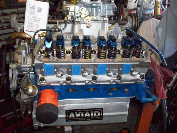
Closer- good view of the oil sender extension fit. Valve covers will go on once the engine is in place. Newspaper is to keep crap out of the 3.5 qts of oil that are in the pan after priming it..
Shot of the top section of the hard line splice. Got much better with my tubing flare kit...after I found that greasing the various bits and oiling the threads of the forming/pushing tool made things work much more smoothly! (we'll see how good I did once we pressurize the fuel line!!!)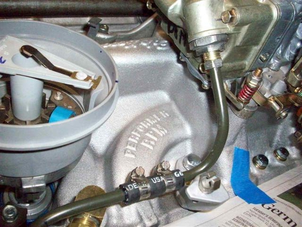
Here's the carb balance/feed tube that I formed up, and new bowl fittings for the 5/16" line. I used a Dominator front bowl, which has two threaded inlet holes on it, like the old factory Ford Holleys used on the 390GT and 428. On those, the line went under the choke housing.... I had to go out and around the side, plus over the top of the jackshaft bracket!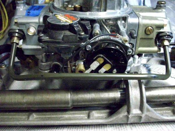
Front view. Watch out for the "hot connection" to the choke!
Special coolant "Y" pipe that was found in the Goose. I copied an original in heavy wall (thin wall would have been fine!) stainless last time around...as all I got with my car was about a 3" piece that was in the final stages of rotting away...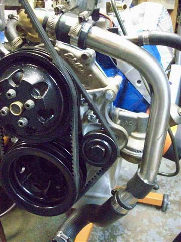
Top view where it attaches to the special thermostat housing (which houses no thermostat in the stock form....) and you may just be able to make out the thermostat adapter, which now measures a much thinner 1/8"!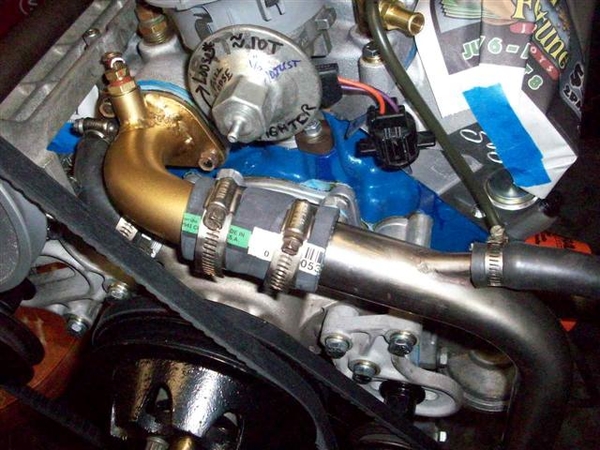
View from the top side.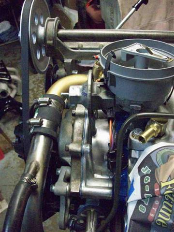
View of the RH side, water pump inlet where I had to remove material from the timing cover fitting for clearance.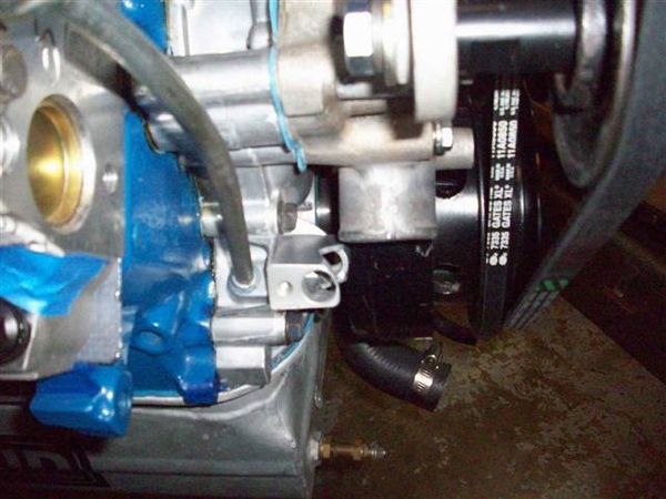
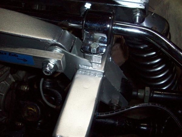
Same view from a little further back. Front jackshaft bracket attachment can be seen. Dipstick bracket. T-stat spacer in place.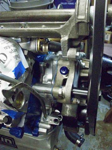
Rear of the intake manifold where I had a piece welded on, to attach the rear of the jackshaft bracket in the stock manner. Only the stock cast iron 1968-1969 type 4V intakes have the boss for this as far as I know. Good shot of my custom made throttle return spring bracket on the left side of the picture, the PCV hose & fittings, and the vacuum hardline tube for the power brakes. This tube will be bent up a bit more to flow around the head. It's still in it's form as removed from the old engine.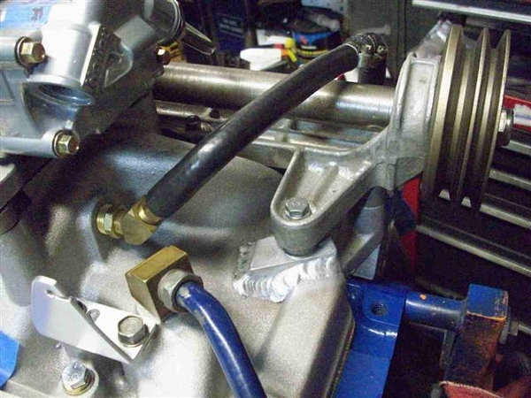
Just a view of the business part of the jackshaft feature.... I wonder about the belt fit....the adjuster is out to the extent of it's extension!
Back at it later today!!!
Steve


Well, the engine is resting in it's new home!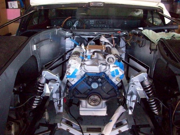
A few things didn't go as desired....
New fuel line protruded just enough at the bottom bend that it hits one of the braces that connects the top chassis rail to the bottom rail....working on reforming it...
Oil filter must be installed AFTER engine is in place....now I know why the previous owners installed a remote filter on my other engine.....
Oil pressure sender stand off was NOT the correct one! DOH! Had to remove the sender to get the engine to set down.... Will need to install the shorter stand off I guess!
Would love to see pics of your oil sender area if you have an engine out!!!
Here are some pic's of how we got to the shot above!
Trying to get three types of chain to fit into the elcheapo load balancer for the hoist...which has a loop on it that doesn't allow "easy" looping of the hoist cable thru....so that we can get enuf overhead clearance in the garage with the old flip up door open! Of course the heads have both 3/8" holes and 7/16" holes and not all of the chains would fit the 7/16" bolts...and the big chain wouldn't fit in the load leveler.....ugh! Since I had no easy & safe 4th point to attach to up front, I used a seat belt and tied down around the balancer and back into the chain connected to the LH front. Worked like a champ! (no pic's of that Rube Goldberg solution....!)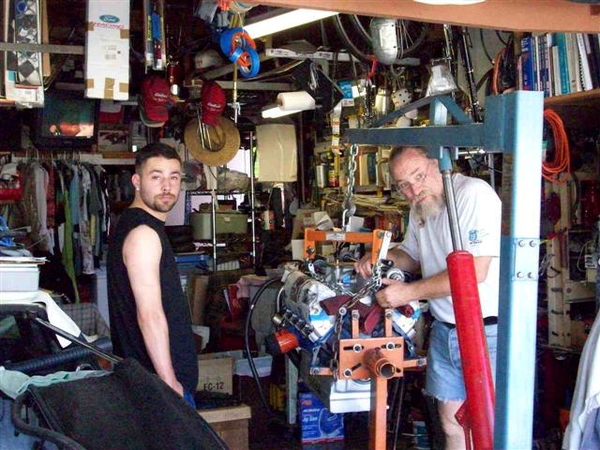
Almost ready....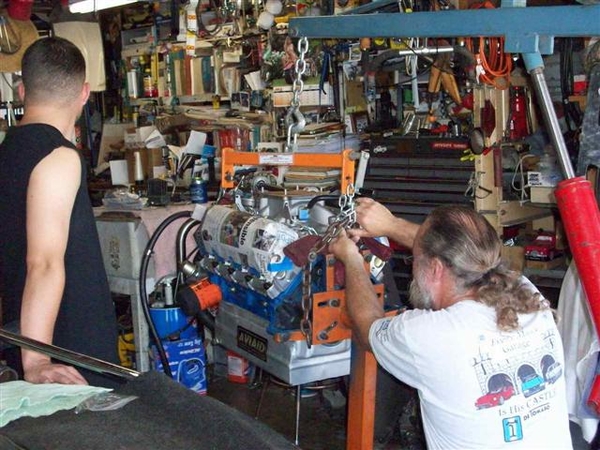
It's gotta fit in here....
Not impressed with lack of progress...he'll be moving shortly!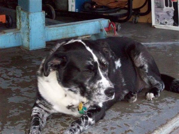
I lost my photographer when we were actually lifting and lowering.....
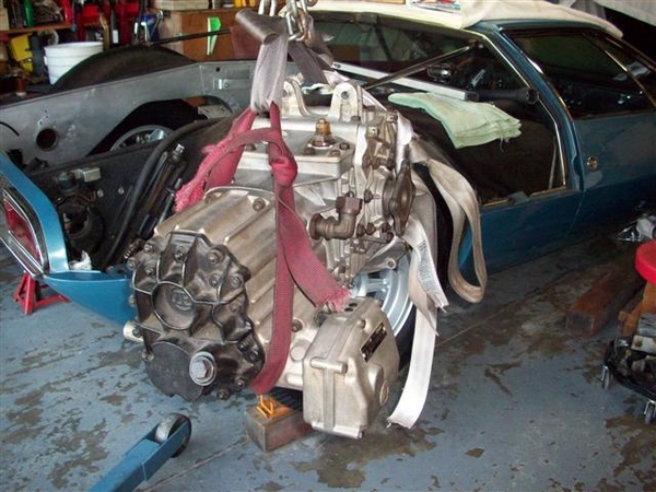
But here we are unable to go any lower...and had to start taking things off..... Oil filter was first thing to go...then this pesky sending unit!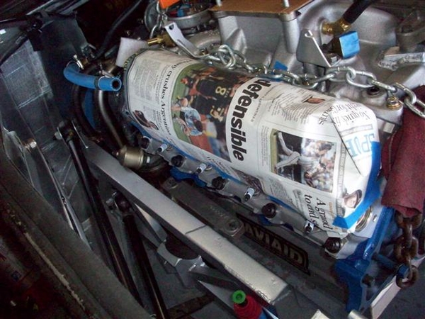
I did find a solution I believe. Will use something similar to what was used in the 1969 Boss 302's with power steering. They used a fitting in the block connected to a remote mounted bracket/fitting(front of the head! Imagine that!) for the sender, with a short flexible line! It will work beautifully!
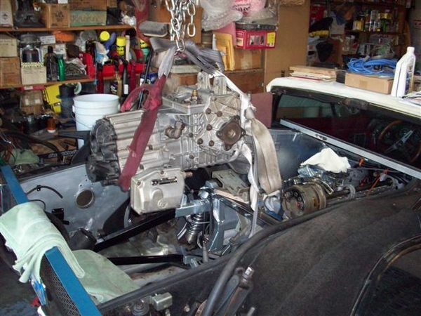
RH side....no problems! NOTE IN THIS PIC Y0U CAN CLEARLY SEE THAT i HAVE FORGOTTEN TO PUT THE ONE PIECE REAR CRANK SEAL IN PLACE!!! THAT GAP IS HUGE!!! This will come to light once the engine is fired up for the very first time!!!!
 ![]()
![]()
![]()
Almost there...checking to see that we don't need to take anything more apart! Removed my new fuel line about this time.... Using the leveler we nosed the engine down to clear the front of the jackshaft bracket, and then once that was in place, raised it up and maneuvered it into position above the mounts.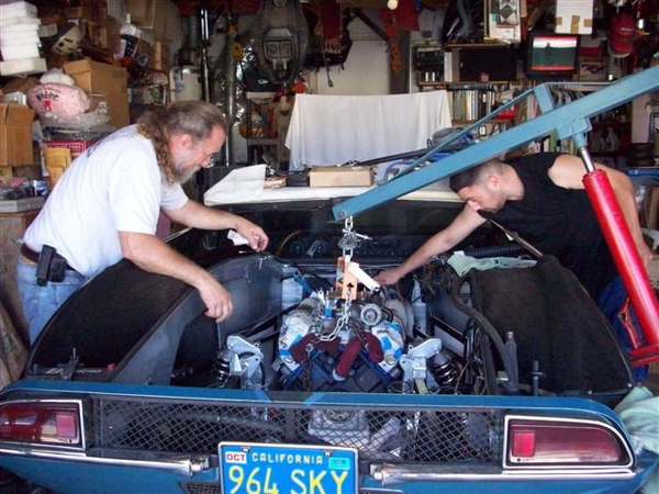
Note how the hoist angle is. From the side, not perpendicular, but just a tad to the rear. The rear tires are on the car, and they are sitting on 2x4's to get it off the ground so that the hoist wheels clear the pan etc. If we needed more "in" I would have removed the wheel and left the chassis up on jackstands, but you'd need to strategically locate the stands so they didn't get hit by the hoist legs!
I was able to climb into the engine bay and sneak the engine mount bolts into position from the rear, by looking down from above to see if we were close to the bosses in the block, and then just push and shove a bit (OK, cheated and used a mirror once...) to get the bolts started and then cinched them up snug, but not a final tight yet! I may raise the engine back up if I can by putting spacers between the mounts and the block....time will tell!
It felt REALLY good to drop the weight of the engine down onto that chassis! That was a lot of load off of my engine stand and my brain! Finally!!!
And that's how we got to the picture at the top!
Steve


Engine install plus one day:
OK, bent, unbent, bent, almost kinked..bent, rebent, formed, deformed and finally installed my hardline from the fuel pump to the top of the engine! I think I now have about 1/8" of clearance between the frame brace and the line.... I didn't have a bender that would do tighter curves that I would have liked to have had!!! I used a variety of bits and pieces in a vice and managed to get the lower bend a bit tighter and also took out a 3/4" or so piece from the original flare to suck it in closer to the pump..... Shoulda known...!
Straightened the bent lower lip of my block plate (aren't yours bent too???) set it in place on the back of the block, and lifted the flywheel in place. Engine needs to be tipped forward just a tad even for the block plate to fit! As it gets heavier...it will want to sit down to the rear.....and hit parts on the fresh paint on the frame!!!
ARP bolts want 80ft-lbs of tight when lubed with 30W oil.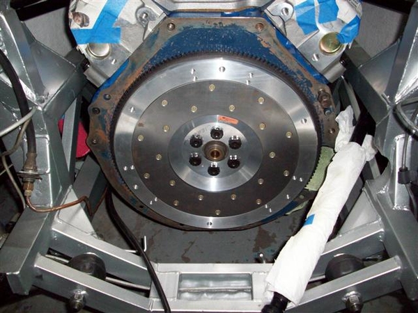
Tapped the pilot bushing carrier in first...so that I didn't bugger up the flywheel with an errant hammer blow! Used a socket to drive it home...once it hit the end of the hole, the entire hammer operation sounded completely different! Much more solid when seated!!!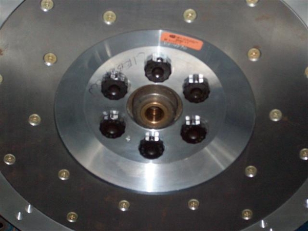
Clutch disc in place with an installing tool: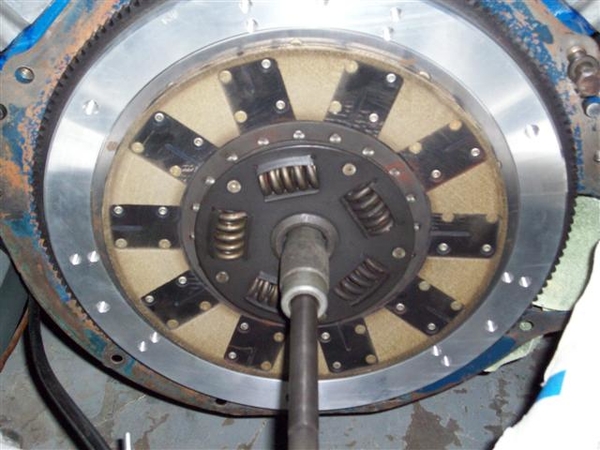
The disc is a Kevlar construction friction surface on both sides. I am VERY happy with the feel!!! No grabbing! Very smooth engagement. This has just under 20K on it IIRC...can't find my mileage log at the moment!!
Carefully slip the pressure plate (stock Ford unit) in place and bolt it down! Again ARP bolts...no spec, so used Ford spec of 20ft-lbs. Hope that isn't too much for aluminum!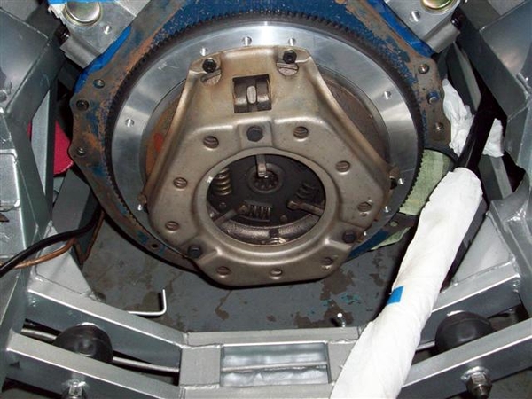
In this shot you can just make out the gap between the center splined hub area and the machined pilot bearing area. No clearance here would be a bad thing. It would mean that your flywheel and or friction disc has worn so much that they are touching...not a good thing!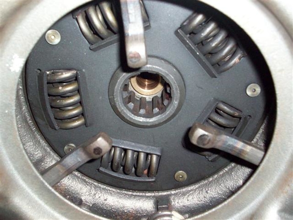
Using the ol' eagle's eye, you can check the work of the clutch disc installation tool before you cinch the pressure plate bolts down all the way! Make sure that disc is centered, or your ZF will not slide into place.....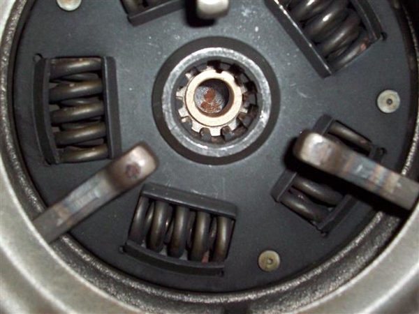
Time for the bellhousing to go back in! This is tricky....to get it in place without banging up the paint! How the heck the factory put these engines in, as an assembled unit, is beyond me....they must have had a hole in the floor that the front of the engine went into and was then lifted up........ Let's just say that it is a tight fit!!!!
At this point, with the bellhousing installed, the rear ladder bar MUST go back in place. (I guess you could wait until you put the ZF back in, but it will be one helluvalot heavier lift once you do!!!) You lift up on the bellhousing and rock the engine forward (watch out for the distributor cap if in place!!!!) and then slide the ladder bar in place on the left and then feed it thru to the right. I should mention that the frame is now supported by a jack under the rear crossmember, just enough to take the tension off of the shocks so that the upper bolts can be removed....
I was able to slip the two bolts in on the RH side, capturing the shock top as well! Here is what I saw on the LH side....but it was expected!
I raised the car up enough to put another 2x4 under the RH wheel to put some tension on that side of the frame and lowered it back down. The LH side was still on the jackstand. It helped!
With the help of a ratcheting tie-down, I was able to pull the remaining little bit back into place.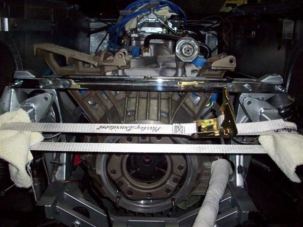
Using my knees and thighs to gently push up on the LH wheel, and lifting the bellhousing with my hands, a third hand pushed the bolt home the last half inch with a firm push from the handle of a hammer. (No hammering on the new parts....yet!)
Being the problem child that she is, the car gave up one last issue....the new center bolt on the LH side would not go in from the front to the rear....so went in rear to front....AND may need to be shortened for clearance with the AC arm on the bellhousing. Here the engine is just resting on this bolt....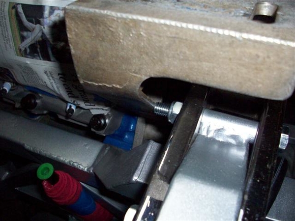
We can make bolts shorter....it's making them longer that's tough!
I connected a few hoses and easy electrical connections....and called it. More tomorrow!
Ciao!
Steve


Tuesday eve....
Installed gas line to fuel pump, from tank. Not terribly easy being upside down and cramped....but it fit.
Broke a tooth during dinner.... roasted chicken and salad....what's up with that! Off to the dentist for another damned crown tomorrow....I hate this "old" thing.....!
Spent a good while bending up the old 1/2" steel tube that fed vacuum from the rear of the manifold to the steel pipe on the side of the frame rail. Could have run hose from the pipe to a fitting....but that would be too easy....
Decided to check my rear jackshaft pulley alignment....went back to the storage shed and pulled out the alternator and adjuster....
All looked well except that I did need to reuse the tiny .110" spacer that I had made up previously! At least that dimension didn't change...I had to trim a pinch off of the key end, but not a big deal.
What did change, is the position of the jackshaft pulley, which now causes the belt to rub against the large pivot bolt at the bottom of the alt. No matter which way I go through, front to back or back to front.....it rubs...
I decided to try the middle position for mounting the alternator. It has always been mounted on the outside position as long as I have had the car, and the wires do not seem long enough to fit to the alternator!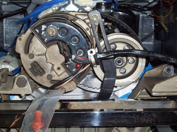
I was able to install the new alternator adjuster bracket that I bought on the way to Reno this year! It actually fits! However, if you note in the picture above , the wires do not fit....they are original ends...and don't look to have been shortened anywhere...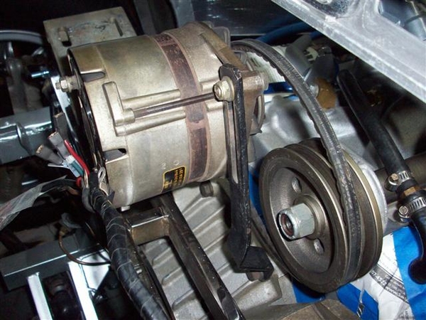
I'm going to go through my pictures of other cars and see if perhaps the rear of the alternator can be clocked slightly different 120 or 240 degrees...to make the connections closer. Just seems like the wires would be sorta taught, hanging out in the air.....
Probably should put a new bearing or two in the alternator as well...check the brushes too....another day!
Ciao!
Steve


Wednesday....
Sort of an "investigation day"...no real progress....
I forgot to note that yesterday I noticed that the lower rubber hose from the Y-pipe to the frame pipe will be too long now due to the motor drop..... Not going to worry about that until the trans is in place and the attitude of the entire drivetrain is in it's place...
This will be the theme for a few things, notably the exhaust system too!
Played with checking header fitment...
This is RH header from Set#1. An early Hall Big Bore is my guess. Very thick flange at the head, not so thick at the collector. Finished with an 80's sort of alumicoat....nasty crap...no way to keep it clean like the new ceramics!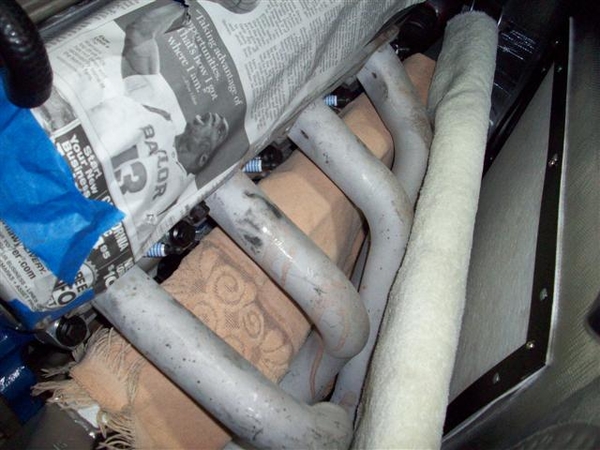
Fit on RH side is actually pretty good. I want to see if I can either adapt easily, or construct a new set of the heat shields that were on the original headers....we'll see!
View at the collector. Good location.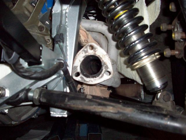
Picture from way back....lots of clearance for the a-arms. I like that!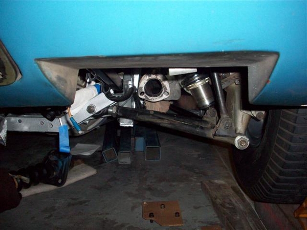
I made a "gauge" of sorts...to help compare set#1 to set#2 for location..ie are they directly interchangeable? Stay tuned...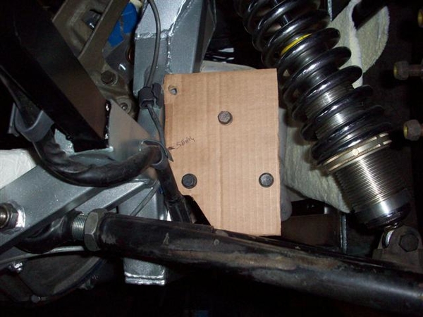
Set#2 RH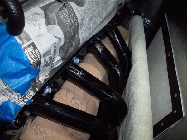
Flange view. A little lower and closer to the frame.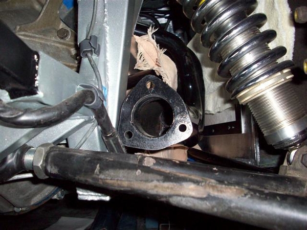
View from way back.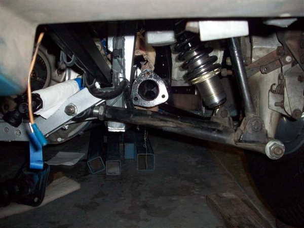
View of template mounted on #2. Note that the other pattern is #1.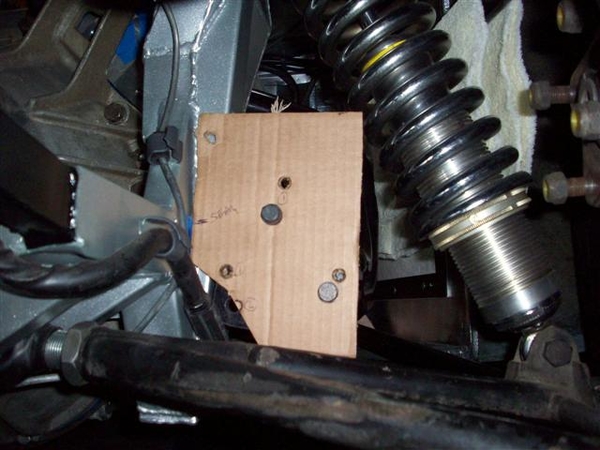
SO answer to the above question, will the headers interchange with the mufflers welded up??? HELL NO! What was I thinking.....how silly!
On to set#1 LH side....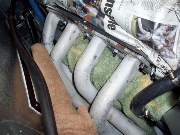
This one has evidence of contact with the upper bar of the 4-link suspension...and is very close to the frame rail too! I will probably attack this with a piece of round stock and a hammer to give a little more clearance...cutting and rewelding the pipes is a messy option....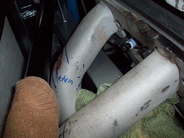
Here is a way back shot of the collector.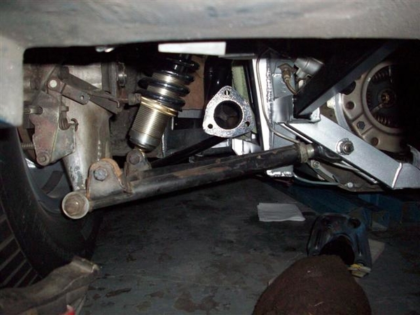
Again, will check this all out once I get the ZF back in place... It is a lot of weight to not have in the car to fit all of this....
Today was like Christmas! FINALLY opened the box that Dana of Mangusta Int'l sent me back when I started this project almost a year and a half ago..... What's in this box you ask? A brand new pair of ANSA muffler copies, in stainless!!! And boy are they a set of mufflers!!!! The pictures don't do them justice...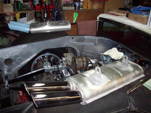
Mounted one up just to see....but I have some concerns about my hangers and if I have them on the correct side etc. Will see what sort of feedback Dana gives me....!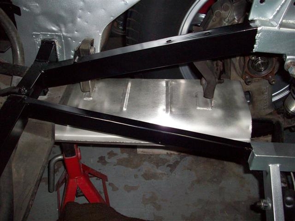
I don't know if my hangers are in the stock location, and I am not 100% sure what side of the hanger the muffler should be attached....
So, that's it for today. Still don't understand what's up with that stupid alternator mounting system...or what I will do about it. Now is when I wish I had some original pictures of the car!!!!! ...way back before people started dorking around with it!!!!
Ciao!
Steve


Thursday:.....I don't remember...that was a long time ago on this project....! ![]()
Friday: Couldn't avoid it....time to install the ZF!!! Something else that is hard to avoid....scratching up the paint trying to get a ZF into the back of a Mangusta! I will need to spend a little time with the teeny brush and some paint...........ugh! It was tough, but then I was the lone ranger on this one...no extra hands or eyeballs...
I didn't take any pictures pulling the ZF out...and couldn't remember exactly how I did it....sheesh this project is taking a long time!!! Again used seat belts....tipped the engine up as far as it would go (remove headers for more clearance!!!!)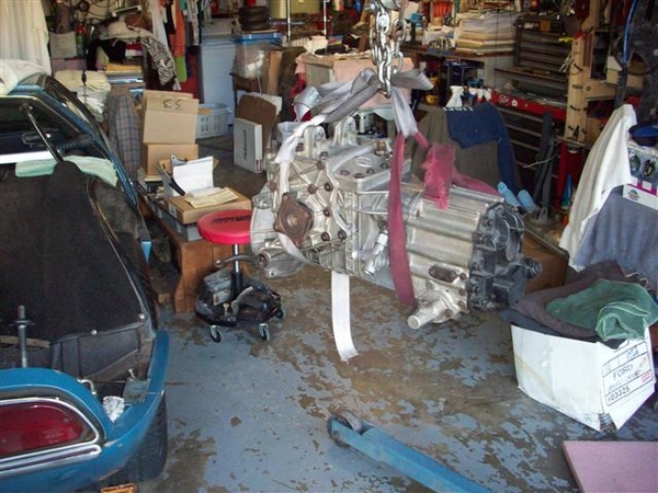
Tried to go in from the side again, like we did with the engine but in the end, going straight in from the rear worked out best.
Just a tad nose up allows you to drop it in place, nose facing the left AC mount, and then rotate it clockwise into position while lowering...trying not to get tangled up in the LH steel brake line, or the frame, or the ladder bar, or the AC condensor, or the rear valance...... Setting it close to the lower two mounting holes, HEAVY towel on the crossmember...tip the nose of the input shaft into position and then jack and lift and push....and voila!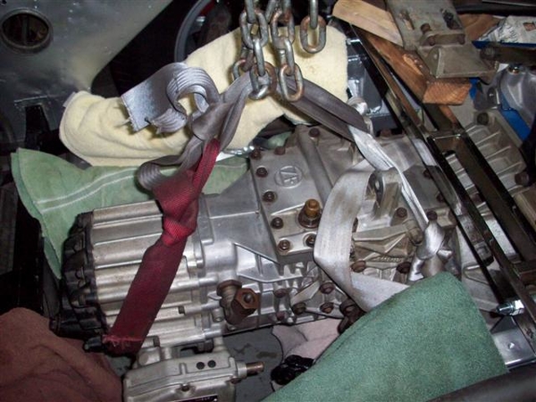
It should be noted that if your clutch disc isn't lined up properly...it will not be half as easy....as this was.....!!! I got real lucky, splines lined up and she slid right into place. Threw on the retaining nuts and dinked around with the rear mount for the rest of the night.
Saturday: worked on rear ZF mount. Needed bolts so took a trip to Orchard Supply for good grade 5 stuff....ended up with some overkill grade 8's for the center two bolts, because they had more "step" on them, and also got some 3" 3/8" bolts to use on the end two mounts, along with my unpatented frame stiffener modification. (Which I forgot to take a picture of...but I think I posted way back in the early pages of this adventure!)
A pair of stainess steel O2 sensor bungs and plugs showed up in the mail! Figured since I was welding...may as well put a pair of these in the tail pipes just after the header flange.... Could aid in tune up and performance tuning on the chassis dyno!
Installed the half-shaft assys. NOTE: with your wheels hanging suspended (frame on jackstands) do not be alarm if all of a sudden your wheels seem to bind at 180 degree intervals.... What is happening, is that your half shaft ends are binding against the ends of the u-joints. One side does it on this car, the other doesn't...go figure..... Once you put the car back down, you will not have this problem....or at least you shouldn't!
Once the half shafts were firmly in place, I installed the clutch slave cylinder, but of course had to take it back out because I couldn't get enough adjustment out of the rod, because some of the threads got buggered up...pulled the rod out, chased the threads with a tap, greased it all up again, and put it all back in place!
Installed the roll pin back into the shifter shaft, and installed the ground strap to the rear of the ZF trans and to the frame.
Started trying to fit hoses and figured out that when I got the last two hoses to try (for connecting the bottom of the Y-pipe to the frame pipe) that I didn't have my glasses along....so ended up with 1.5" hoses instead of 1-3/8"!!!!
Sunday sunday sunday!!! Sorry...drag races are happening up at Sears Point....couldn't resist!
Played with hoses today! I hit the Kragens with my old hoses to return, and my old hoses from the car...my glasses, 6" steel rule, and a tape measure for anything over 6"....
Found a Gates #22185 hose of the proper 1-3/8" diameter! I was able to get two hoses that will do the job...give me a spare to carry in the tool box... for only $8! The hoses I was returning ran $17-20!!!
I cut this apart, with the RH section as you see in the picture being my primary piece, and the LH section as my spare, but I found an errant slice in the area near where the clamp would go, under the label....so I wouldn't want to chance that.....of course once I cut the hose up I ruined my option of returning it...but for $8 I'll order another and be real fine with it! Hang it in the rafters!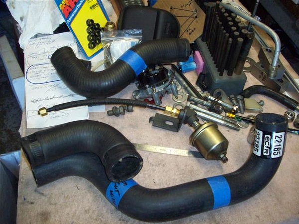
My old lower hose is at the top of the picture....and can also serve as a spare for this too! I'm surprised at the difference in length of new to old...but then EVERYTHING but the actual Y-pipe and the under frame tube is different....gotta keep telling myself this...! Installed the "uncut" piece in the car...one hose to go! (Ordered another potential for the water pump hose.....but the flex hose I have may work in a pinch.....read that as "requires trimming prior to installation.....")
Something else to note in the picture above...my solution for relocating the oil sender unit! This piece is donated from a Boss 302 parts book. Cars with power steering and a Boss 302 needed more room in the area....so this was the solution. Mounted it up with a 5/16" bolt to the front of the head and it came out nicely! Cost me a Ben Franklin to do it....but all I had to do was pick up the phone to National Parts Depot (Mustang parts+++) and it magically appeared at my front step two days later, already put together..... (I tried looking for the fittings to do this....but gave up....I wanted to finish the car, not manufacture everything needed....)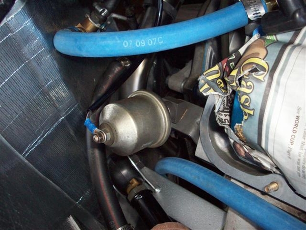
It will clear the valve cover just fine, and everything else...... Nice clean installation that perhaps others of you could use as well!
Here's why....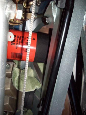
You cannot see the oil line in this picture, but with the fuel pump, the oil sender extension AND the oil filter all in there....it's tight! This car had an oil filter remotely mounted.....so I never had problems previously! But since the threads in the remote adapter weren't threaded deep enough for this engine insert, I have left it out for now and will change filters with the large mess that everyone else has......!!!!!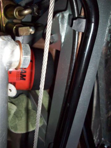
As a result of the remote filter...I never was aware of how tight things are there...including even getting the oil filter up near the engine! The filter would not physically fit between the oil pan and the frame rail, until I unclipped the vacuum hard line from the rail and moved it just out of the way, as you can just make out in the second picture above.
Took care of a few things on my "Don't Forget List"!!! Tightened lower shock bolts, motor mount bolts (to engine), and the top clamp on the vacuum hose to my bent up steel line. Still have a few things to do, but that's OK as long as I have them written down!
Installed some heat shield to the back of the firewall door to replace that garpy crap that DeTomaso used for water collection....I mean insulation.....
Dug out my sway bar and set that in place. Due to all the bolt length and orientation changes due to the attempt at a simple frame stiffener, I will need a spacer between the frame and the sway bar clamp to raise the bar to clear. I checked this out before, and I think 1/2" will work, but will check again and see if I can get away with 3/8"! That is where I left off this evening.....looking for suitable scraps of material or a willing donor!!! None found yet...but it's gotta be around here somewhere....!!!
Ciao!
Steve


The march continues.... (from two days ago..no work last night or tonight due to grandkids at the house, and a mystery clutch malfunction in the 68 Cougar (son's car now..) plus taking the wife out to dinner and a street dance sorta thing...pay the dues....!)
Called about header coatings, Caps of Fresno appears to have a high temp (1700 degrees) version that uses titanium...or that's what they call it.... instead of aluminum, which melts at 1300 degrees and can then separate....so for no additional cost, they can do the higher temp job! With blasting the old electrostatic coating off of the headers I want to use, they can still turn around the job in 7-10 days! Great!!! More later..
I worked on the sway bar spacers next...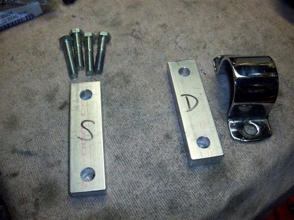
These are cut from the same 1/2" x 1" bar stock that I made my prototype chassis stiffener bar from.... Cut to length and drilled with 3/8" holes. I have not yet beautified the rough edges on the ends....
I also ordered some smaller diameter headed 12 point 1-1/4" long bolts....as trying to use the full headed bolts causes the side of a socket to contact the ladder bar and may or may not fit down onto the bolt! I have seen many a socket head (allen head) bolt used just for this reason! These things look like 12 point header bolts....for lack of a better description. Will post a pic once I get them....more special order from Fastenal! I also ordered a 5" long button head bolt to try was an alternator pivot bolt to perhaps help with my belt interference issue.....
Back to sway bar spacers....
Installed left and right....I gotta be getting close...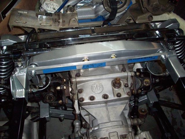
Close up: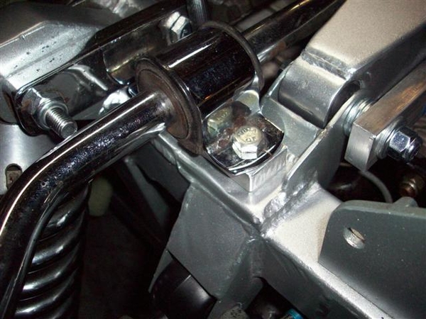
Last thing I did the other night was to get down my original air cleaner and check the fit! That was the goal of all of this work after all!
Well, it looks real good....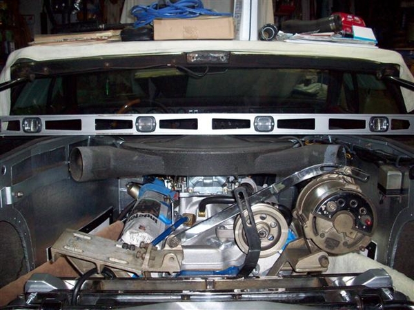
But success is fleeting and not to be found here..... The air tube horns are about 1/2 proud on either side, and the center of the air cleaner would just contact the shield by 1/8-1/4", if you are to believe that they would be flat... I used a level here to simulate flat....of the closed covers....
The carb stud also is proud by about 1/2 inch, but I could effectively deal with that in a creative sort of manner if I had to...
The long ending to this story will be to go back to my Performer intake with a shorter carb mounting pad.... I have the manifold but it needs the ports enlarged, and the rear mount piece welded onto it... Installation is something that I don't see as being too large a deal now that I have been through everything else!!! But for now, we run the Performer and I dig out my old low profile air cleaner to get out of the garage and down the road a few miles!
The lower carb height will probably cause me to use a manual choke setup....which after looking at this...is probably what I will need to do with the Performer RPM intake that I have installed presently. Just too much stuff over near that pesky center bearing area of the shaft bracket!
....I thought my measurements were more foolproof....so much for RevA!!!
Gonna go post some header pic's in a new post!
Ciao!
Steve


quote:add some exhaust shields similar to the OEM ones....after I find some .041" aluminum sheet
Wednesday the 28th.....
Time for some pictures!
Last week got detoured a couple of days working on a clutch job....
Those aren't DeTomaso parts!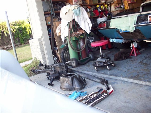
Son's car came up with a lame clutch pressure plate...same type as used in the Goose! Couldn't find anything in terms of a smoking gun as to what failed....aargh! A new pressure plate seems to have solved the problem...but also fixed some minor naggy issues, like bending the equalizer bar to clear the shorty headers, and welded up some things that were starting to show their age!!! (and bad gas welding skills of the author....I love my MIG welder...!)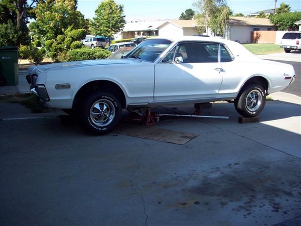
Found these exhaust flange gaskets which seem to be a perfect match to the flanges that I got with the new mufflers from Mangusta Int'l, which fit my old Hall headers. I may need to enlarge the holes to fit the pattern, but there is plenty of meat to allow this. There is a raised sealing portion and it is metal jacketed on both sides, so no messy "header" type gasket battles! About $4 each. Sorry for the crummy picture...camera just isn't what it used to be...!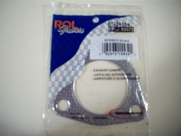
Traded in my little heater hose that goes from the water pump outlet to the hose on the firewall. Fits very nicely! About $7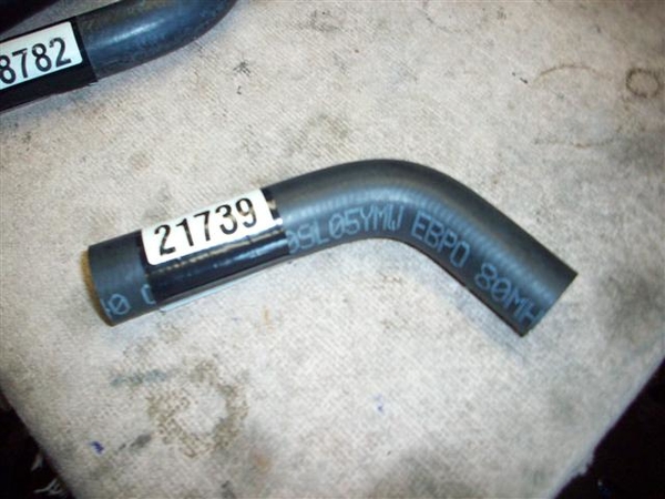
Installed!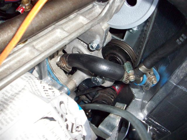
Received my new lower hose which connects the water pump to the lower chassis tube. Cost $20.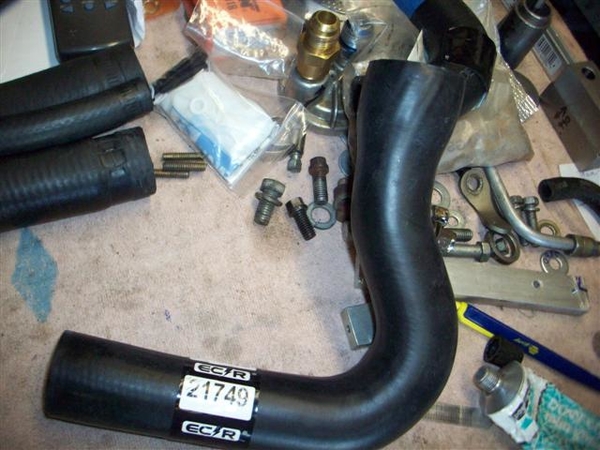
Needed to do just a tad of trimming to get things to line up and not bind.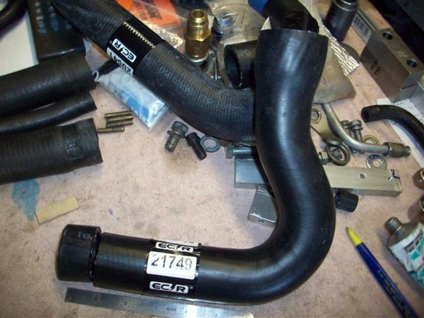
I took one inch off of the lower end. It should be noted that this hose is 1-3/4" at the top and 1-3/8" at the bottom, just what doctor DeTomaso ordered!!!! (last hose was 1.5" at the bottom and required lots of hose clamp tightening!
Tools that made the job MUCH easier!!! You physically cannot get into some of these areas to tighten up hose clamps....but these little buggers saved the day!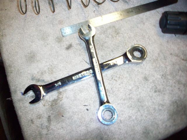
Here is a shot of one area where the screwdriver just wouldn't cooperate!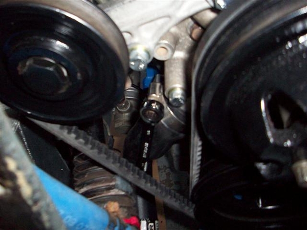
I won these at one of the PCNC Christmas party raffles and I am beginning to like them a lot! I had a version of Craftsman wrenches, but the gear teeth were "more coarse" where these have more teeth and offer more ratcheting for less movement! (Finer the teeth, the more work gets done in tight places!)
Glued the valve cover gaskets to the valve covers, installed the V/C studs into the heads and started working on the coolant overflow tank....which is where things went awry last night!
I was mistakenly thinking that "all I needed to do" to complete the cooling system was to slap the overflow tank in the bracket and connect two hoses....Not to be! The clamp which is supposed to secure the tank to the firewall bracket, is about 1/4" to long on each side. I had wrapped the tank in some 1/16-1/8" thick foam tape, but it was not enuf..... SO, gonna scrounge up some thin tin and make myself a new one!!! Seems to be the only option.... OR do like the PO did, and wrap it with VERY thick foam tape....which was super ugly.... I'll use tie-wraps before I do that....!
Spent tonight doing PCNC bookkeeping in prep for meeting tomorrow night. Will try and order up some material for exhaust hangers yet before I hit the rack...internet never closes!!! ![]()
Steve


Saturday,
In the "some progress is better than no progress dept"....
I found some 1/16" thick by 1.5" wide aluminum stripping at Orchard Supply Hardware (didn't have steel...![]() ) to fab up a new coolant tank strap. Came out very nice....we'll see how well it holds up!
) to fab up a new coolant tank strap. Came out very nice....we'll see how well it holds up!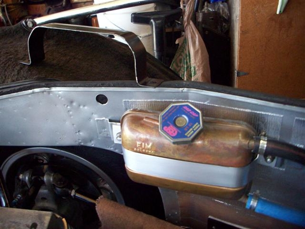
With this piece installed and hoses connected (excepting a hose from the tank to an overflow catch can....) I do believe that my cooling system is sealed and ready to receive liquid!!!!
In the "going nowhere fast dept"....
My alternator mounting and belt interference still continues to be a PITA!
I took possession of a new 4.5" long 3/8" "button head" bolt to try instead of the 10mm hex head bolt... While it appears to clear the belt now, the slightly smaller diameter of the fully threaded bolt, and the fact that my alternator spacer is about .025" shorter than it should be, allows the alternator to rock all over the place.....much more than it used to. I can fix this with a new spacer, or a .025" thick spacer for the spacer....more lathe time! Perhaps I'll shop it out to my dad.....
I also am going to try and get a real metric bolt and cut the head down on it. I think I can do an abbreviated button head treatment to it and perhaps win! Leave just enough hex on it for a socket or a wrench to grab it... I found the bolts in the Fastenal catalog, just need to order one...
In one last "you've got to be kidding" dept, to top this all off, I had installed my new ginchy valve covers (not yet revealed in photos) earlier in the day, thinking that all is well....can finally seal up the engine....WRONG! In order for me to remove this alternator bolt, I must remove the RH valve cover now! THAT was NOT a part of the plan.....valve covers may hit the scrap pile later....we'll see.....go back to a modified version of my initial idea....but not an emergency issue, nor is the alternator belt thing as I have options.... Put this crap on my "fix next winter" list....
Have a great day! I think I'm going to replace that fuel line from the tank to the pump. In thinking about it over the past few weeks, the stuff was starting to get hard from the additives in the fuel....and since I have no fuel in the tank, I have new fuel line, and the car is up on blocks....I may as well do it!
Steve

Monday...
In the close but no cigar dept, a couple of things....
I think my exhaust hanger strap is too long...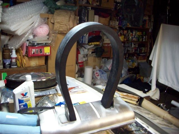
This is the 2" wide by 1" thick material I got from McMaster-Car. Will need to do some bandsaw work on it! Where's my bandsaw.....
These hanger reinforcements were "supposed" to be the correct part over the phone.....duh!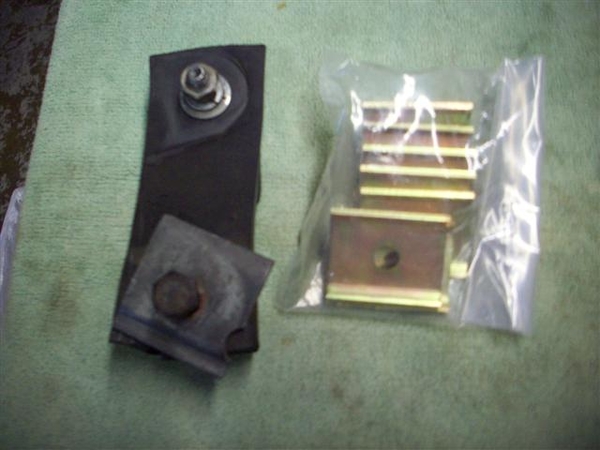
Turns out that it appears that the Panteras used the same reinforcement and also tubular spacer....but no one has piped up and said that the spacers were used on the Goose yet....Daryl?
8-31-10 update: Was looking through the Goose parts book, and found the hangers and reinforcements listed on page 52, two lengths of hangers specified from Fiat 1300/1800 models, and 16 of the little reinforcements and 8 steel sleeves as being sourced from the 1300 model Fiat!
Just waiting for headers!
I'm a little concerned about the radiator cap on the coolant tank...seems a little tall....but it doesn't appear to have been replaced either.....I do not want it to contact the shield and hose it all up!
Posting some jack pic's over in the "tool kit" thread.
Cheers!
Steve


Whoo HOO!!!
Wife just called me at work and informed me that I have some freshly coated headers waiting for me on the front step!
I know what I am doing tonite!!!
....I'll try and remember to take some pic's....before I put them on....
OK, unpacked the newly coated headers and boy were they packed! Came to me in a Hooker header box! The 1700 degree finish is about as grey as the background of this text. It is not the bright and shiny aluminum looking finish that you see so often. I had heard that the 1300 degree coating can lift when in tight confines.....well, you cannot get much tighter than a Mangusta! Cost was no different....and I do NOT want to be in here again any time soon dorking around with headers!
Insert pictures here:
RH header: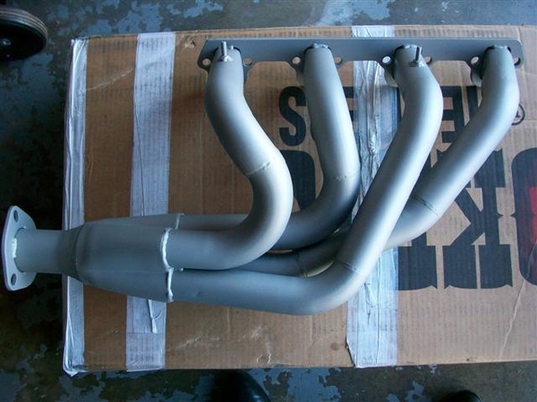
LH Header: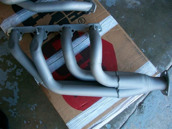
LH mods at front two pipes to clear upper control arm.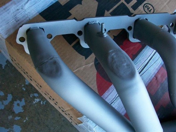
Underside of front tube on LH header to allow more clearance of frame rail!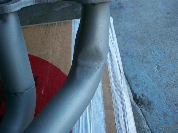
More misc: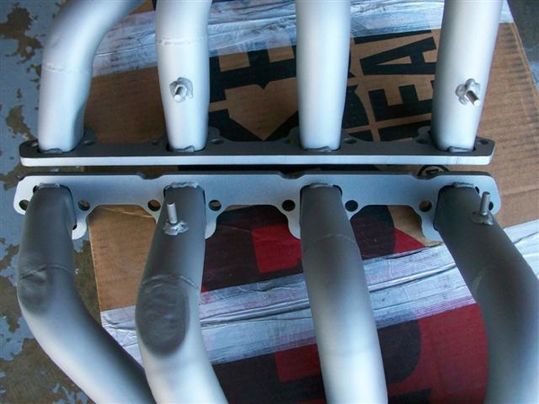
This is a deeper grey finish as I said above. Sorta grows on you! Is very resistant to staining and grubby finger prints!!! Pretty tough, but can be scratched....oops!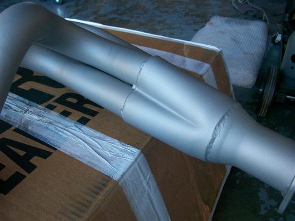
Of course since nothing can go smoothly, and why would this part of the job be any different....when I did the original fitting, I did not have my studs for the heads yet. Using aluminum heads, I figured I'd use studs to save the threads in the heads. I used a gasket and some short header bolts to see how the holes looked and removed material where it was in excess. (THESE ARE THE WORST FREAKING HEAD FLANGES THAT I HAVE EVER SEEN!!!! THE BUILDER MUST HAVE USED CRAYONS TO MAKE HIS PATTERNS.....) OK, that rant aside, these things REALLY suck....I mean how many times has Ford changed the small block exhaust pattern in 30 years? Correct answer would be: ZERO! NONE! NADA! I digress....
SO the headers didn't just slide on.....I filed and I ground with a carbide ball, and eventually they slipped right on like they were supposed to! This time, I dragged an old head out of the shed and used my extra 4 studs to test fit on the bench!!! Wasn't fool proof, but I was able to see better, areas that may be an issue...but still needed to trial fit the RH header about a dozen times before they cooperated!
I also ran into a couple of the studs that were tooooooo long. I could only get 1.75"or so studs, with 5/8" of coarse threads to go into the heads and I think a 1" fine threaded section to hold the headers on. I knew I may need to shorten some, but I wasn't going to get too anal and shorten them all..... (If I had my own metal lathe, my name would be asshole... ![]()
) SO, I had to shorten 2 or 3 on the RH side, and 1 on the LH side due to the angle that the tubes were welded in.....a cut off wheel, and a thread chasing file were all I needed to make this a very short job! I ran nuts onto the stud before I cut the bulk off, and that way, when removing the nuts, they chase the material back into position...clean up with the thread file and off ya go!
I also had to do some minor malletizing on the area adjacent to the studs so that the whippy dippy lock washer devices I picked up would fit, but in most cases it was due to being unable to get the 12pt reduced size nut in place. Conventional header bolts probably would have fit by a few hairs.... I eventually figured out that if I could get the nuts in place and finger snug, I could use the largest screwdriver that I owned, with a nice smooth flat blade, and slide it down between the nut and the header pipe. A few raps with the hammer and I moved the metal just enough for my small headed wrench to fit properly. Large headed wrench will probably be a no go..... (Some day I may look back and curse myself for all of this 12pt hardware and for being so anal....OK I kick my butt all the time for doing that already...nothing new!)
So, a couple of small scratches near the bolt/nuts on the tubes, but I'm not worried about that. Wouldn't be the first car I've seen with super nice finishes on their headers.....with all sorts of damage up by the bolts from sockets and what not!!! I plan on fab'ing up some stock type exhaust shields to "suggest" what the originals sort of looked like...which should hide these transgressions anyway! That is a later job....much later.....
I looked at my muffler to header fit, as I was thinking I would need a couple of 45's welded together to get an "S" shaped inlet pipe to the mufflers, but it looks now like the "kick over" will only be about the width of the pipe (1-7/8" OD pipe), so I think that just leaving it straight will be fine. We'll see once I get to fab'ing up hanger straps etc.
Oh, and the reinforcements and inserts arrived from Panteras by Wilkinson, and they look great! Just like my originals only shinier!
Gotta take the wife out for dinner tonite....to celebrate 26 years of slavery..I mean marriage! Anniv. was Wed, but I was out in the garage working....I took her to lunch earlier in the day, so I actually did pay attention to her..(!!!)and tonight was better for dinner due to a live band in the square downtown right next to this little Italian restaurant.....go hang out until it cools off!
Ciao!
Steve


Just a quick post....
Hanger fabbing!
I took my big piece of rubber stock and used my buddies band saw to cut the short pieces to length. Rubber does not cut easily with a narrow toothed blade... Holding the cutting line "open" a tad to take the pressure off of the blade worked well. Free cutting was best, as I tried using a fence but it would just bind up. Pulling the little 1/4" flap away from the blade helped as I was narrowing the 2" pieces down to 1-3/4".
Marked up some holes based upon where the reinforcement pieces went.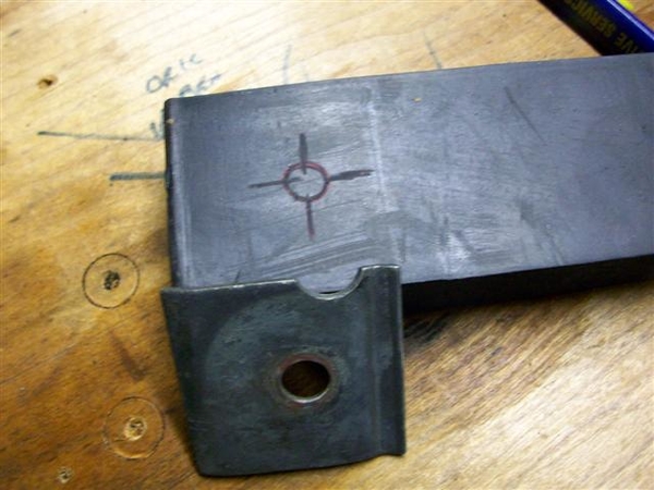
Using a 1/2" wood type bit with no lube.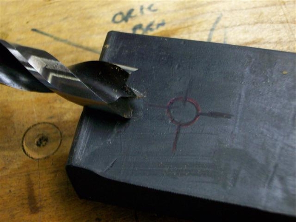
Slower RPMs worked well, backed up by drilling into a piece of wood. Trimmed boogers off with an Exacto knife.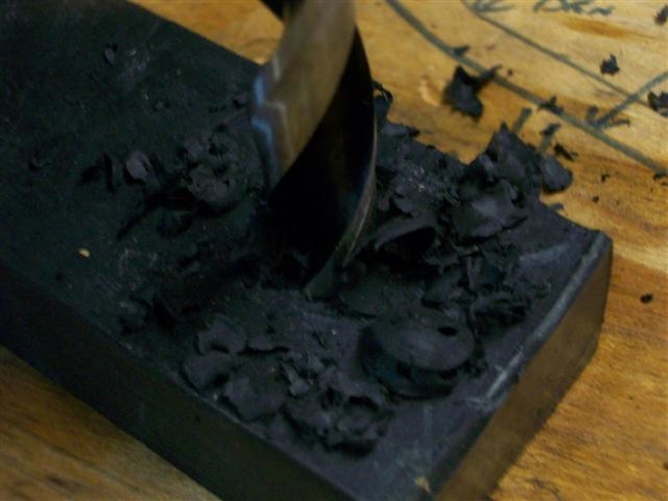
Stuffed in the small metal spacers.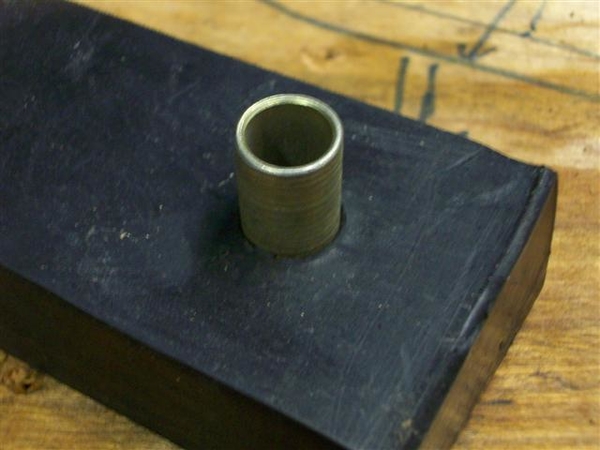
Dorked around with heights and marked the slots of the muffler brackets. Slots allow for slight height adjustments, or you can just make them to fit to the top of the slot.....I aimed for the middle...
Rear hangers are pretty much vertical. Front hangers deviate...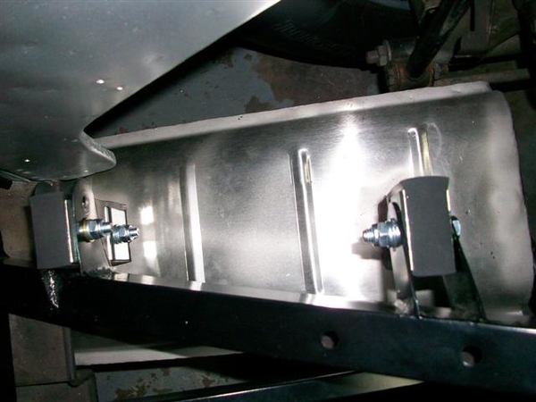
Tried to make things close to level.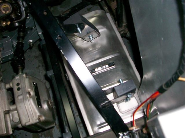
These cars are not symmetrical...
Fab'ing up the inlet pipes to the mufflers. Left side went fairly easily. Right side was a bugger...ended up Frankenstein'ing the pipe..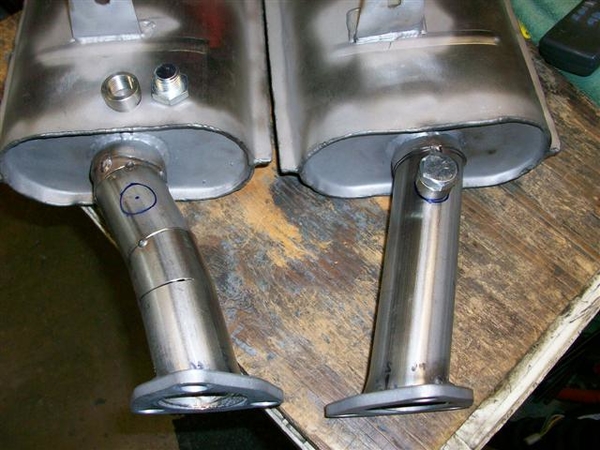
Franky!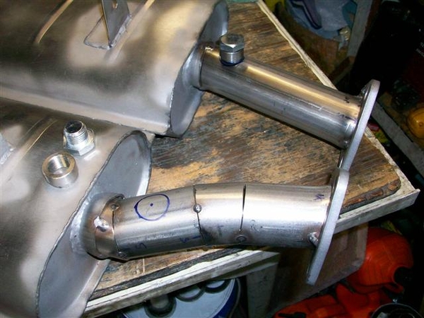
Mufflers are off at the welder getting the stainless steel welded up where I had to Frankenstein the RH inlet pipe... I tack welded everything in place.....let them pretty it up and put in the O2 bungs for me.
Tomorrow! List grows shorter! If I don't get it to smoke test Tuesday, Wed will be smoke and fire! OK, at least turn on the ignition, check for smoke, put gas in the tank and carb, and see what happens!!!
Ciao! More pics later.....it's late!
Steve


Well,
This was supposed to be the final post! Got the car running tonight, but not yet drivable!
Worked on finishing up the final bits on my list....
Cleaned up the muffler outlet areas in the body and installed some heat barrier..."just in case".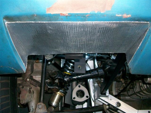
Picked up the mufflers from the welder earlier at lunch. Came out very nice!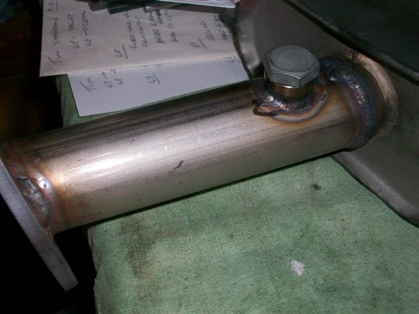
Fitted up the mufflers to the headers, tightened up all the bolts. Figured out earlier in the week that I shorted myself 6 of the little reinforcements for the muffler straps so ordered them from Wilkinson earlier in the day. Should be here by Thurs or Friday, but don't need them for now...
They look really good!!! Sorry, no pic's it was dark!
Son helped me put on the RH valve cover, spark plug wires, and fill the cooling system with water. Put some gas in the tank a little in the fuel bowls, a couple more quarts of oil in the pan and took the car down off of the 4" wood blocks it had been sitting on! Wow, back on the ground!
Fired up right away, but a fuel leak at the rear bowl inlet (my custom made transfer tube) had me scrambling to tighten that a few times....it wouldn't seal...but eventually convinced it that it wanted to seal!
Was running retarded, so tweeked the distributor a hair clockwise and she then idled up and smoothed right out! Warmed up nicely as one would expect with a new engine!!!
Ran it for a few minutes and then shut her down....only to find a water leak out the front of the water pump!!!??? HUH!
Found an extra mounting hole (probably for the alternator adjusting bracket when installed in a front engine config.....) that was open into the main water outlet! Now this the same water pump I was using before, so this is a mystery!!!! I know I didn't plug this hole previously! Or at least I don't believe I did!!!
As it cooled down, I dug around for a short 5/16"-18 bolt, lock washer and flat washer, and some Form-a-gasket and tightened it into the hole. Refilled the system with water, bled it again...and fired it up! Made a lot of difference as now the temp stabilized right away at the t-stat value..... fans on, no air into radiator ie external fan.
Here is a shot of the plugged hole. It is the center recessed bolt head in the center of the pic!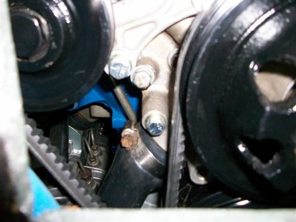
Ran the engine for about 10 minutes or so more, up to temp and then some, still haven't set timing, but keeping the rev's fairly low yet...rev's nicely very crisp throttle response with the Holley pretty much out of the box! Have not messed with idle mixture screws yet either!
Shut it down to clean up for the night...so I can get into work early....ugh! Checked under the car and found a tragedy!
The gulf coast has nothing on me!!! Texas tea...30W flavor!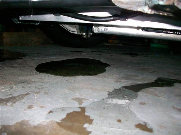
Something is amiss out rear of the engine. Either I totally pulled a boner mistake and forgot the rear main seal (single piece get's installed last....) when it was on the engine stand, or my one piece silicon oil pan seal got bunched up somewhere...or there is something amiss with the crank oil seal surface.....
Enough for tonite, took pic's, tossed kitty litter on the evidence, and closed down the garage.
The saga continues.... But it's gotta be something simple....!
Ciao!
Steve
PS: I hadta look! Checked the gasket set box where I had tossed all of my extra gaskets from intake manifold fitting etc, and didn't find the rear seal. So at least I put that in.... Perhaps not the proper direction, but I believe I was cautioned about that, and I double checked the shop manual too.... damn! That would have been too easy! Ok, not that easy to fix...but easy to figure out! Crap!


quote:But it's gotta be something simple
OK, let's just say for all practical purposes, this was a TV show, with say Chip Foose in it, the cast is assembling an exotic "make over car" and one of the mechanics forgot to install a seal somewhere.....since they were going to tear the car apart again anyway before final assembly, it really didn't matter much. Just a PITA!
EDIT 04/06/20 I built the new engine in 2008 and it didn't get around to installing it for two years, as the car was running..... When I tore the old 'Bird engine down and after the initial assembly, I left the rear oil seal hanging around on my work bench for some time as a reminder to get a new one. (Well that didn't work....... !!!) I eventually got tired of working around it, and rather than tie it to the engine/stand/etc as a reminder, I tossed it in the garbage telling myself that "I would remember this!" HAH!!! How we lie to ourselves sometimes!!! ![]()
![]()
![]()
If you scroll back up to my post on 7/12/10 (page 4 of posts) the top picture of one of the posts has the rear engine view as installed finally in the car. You can just barely make out there is no seal..... This is a low res pic, but on my higher resolution original I could see that I had no seal installed!!! At the time, this was consuming so much brain time that I couldn't get to sleep, so I came out to the computer and cruised thru all my old pictures until I found that picture and realized what I hadn't done!!!!
I've reposted a better pic with no seal for your convenience!
End of edit! Cheers!
Seal not in place: BIG GAP there! DUH!
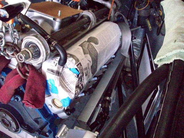
That's my story and I'm stickin' to it!
So now that I have torn every thing apart and installed the rear main seal, as my last task in the engine rebuild....I've started the reassembly process.
Seal in place: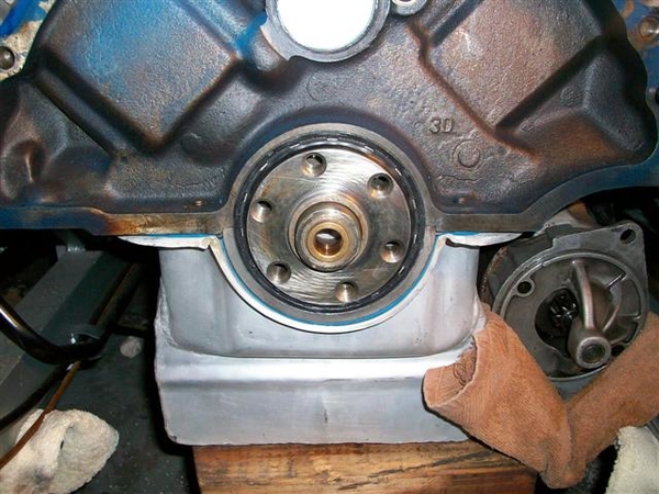
Local shop recommends a fine coating of sealer on the outside of the seal. My 91 shop manual references a section on installing this seal several times....there is no section! (21-1...)
Patience, a 1" steel punch of sorts, and a plastic mallet was all that was needed to put the seal in place. A thin coat of oil on the inside seal area...and tap it in flush with the rear of the main cap.
After de-oiling all of the flywheel, block plate, bellhousing, flywheel bolts with solvent, I put that all back together.
Flywheel bolts got "The Right Stuff" on the threads.....(found the ARP thread sealer with Teflon later....), Ford Tech says used RTV and torque to spec.....75-85ft-lbs.
Torqued the pressure plate bolts to 15ft-lbs on the aluminum flywheel. Used a conventional alignment tool for the disc, which proved effective as trans slipped right in place! No muss or fussing with mis-alignment...
Here is a shot of the front of the ZF with the throwout bearing in place.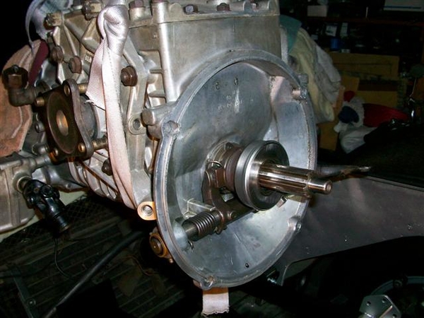
A few more shots of the ZF going in. Tipped the rear of the engine up (disconnected exhaust at the flanges). It should be noted that this time, I removed the rear ladder bar. This gave me a LOT more room to work with to get the trans in place. Should have done that the first time!!!! Excuse me, I meant during the "trial run"!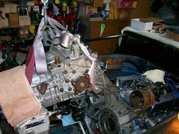
"Easy does it" is in order running the engine hoist. A few towels to keep paint on the metal bits...and the fancy sling made up of old seat belts! Works great!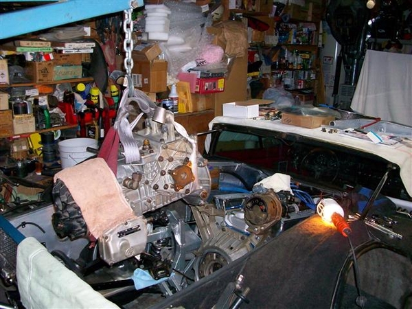
The seat belt sling actually allowed me to lift up on the rear of the trans to give me a slight nose down attitude. Setting the towel, folded up a few times, on the rear spare tire support worked great. Just have to watch out for brake lines etc.... basically everything!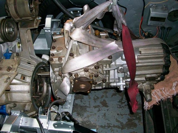
Lower real slow, check to see you are not hanging up on the studs and bending them!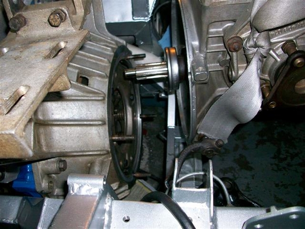
Almost there....slight pushing and pulling and minor up/down with the hoist and it slipped right in place with no opposition! Wow! That is a new concept!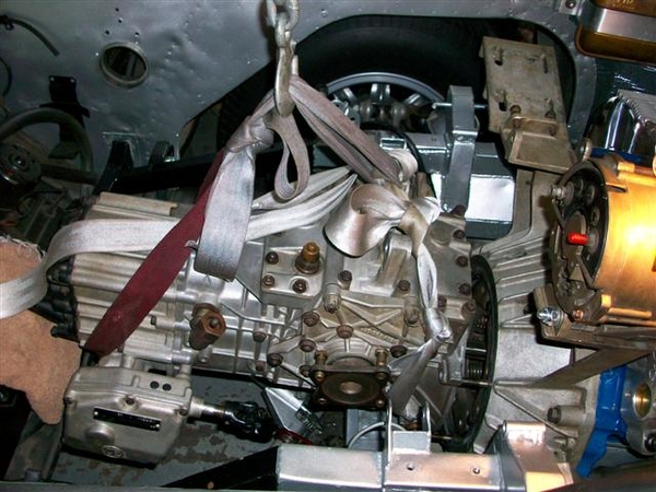
And here is where our hero left off tonight.....ZF is sitting in place (on a 2x4 on top of the cross member) and is bolted snugly up to the bellhousing!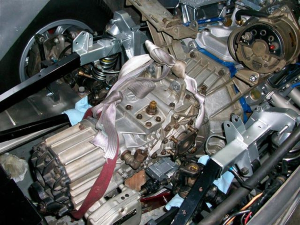
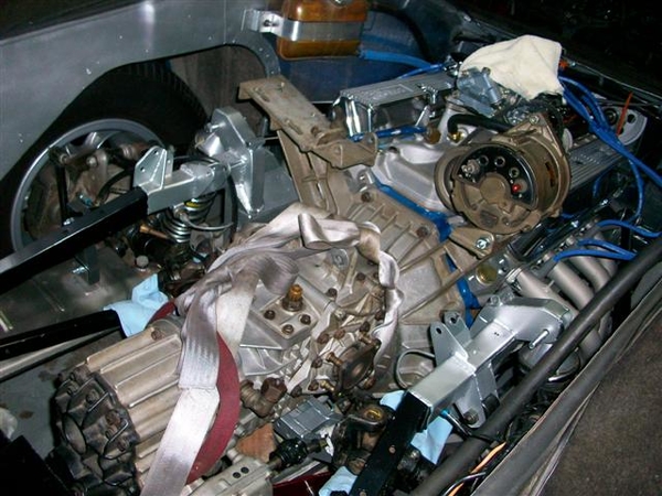
Tomorrow I can finish final tightening of everything else, reinstall the crossmember, ladder bar, sway bar, exhaust bolts, axle connections, speedo cable, shift linkage... adjust the shifter mo' better, and may be see if I can get out of the damned driveway with my new lower oil pan!!!!
Time for some sleep so I can get my butt home early to dive back into this!
Ciao!
Steve


quote:Originally posted by Kid:
Your topic really reads like a good thriller Steve, and I enjoy reading it
OK, here is my "last" big entry in this thread....I hope! ...barring any more rookie mistakes! ![]()
No pictures yet....the unbroken camera (wife's!) was at the races with my son.... There will still be a few things to take care of. Like fabricating up an air cleaner to resemble the stock one, but will have more of a dropped base for clearance...OR I swap the intake to the lower one....next winter! All else that I want to do is normal stuff....upgrade fans and fab' a fan shroud, install the AC compressor and charge the system (*find the leak too*), install braided front brake lines....pretty short list actually! Then drive the hell out of it!!!!! ![]()
Ok, don't forget about fixing the parking brakes too....
Thurs: Busted hump putting all the stuff back on the car...but quite frankly, in about 3 hours or so, I was done, or back to where I was before I did the BP thing on the garage floor! Ladder bar, trans support, sway bar, axles connected to ZF, mufflers connected to headers once again. Spent a good while adjusting the shifter...no 21mm wrenches....and I had to dork around with the trunion....it appears to have been raised as high as it would go, and to get more shaft "length" through "less angle" I dropped it down a bit, tightened rear lug nuts, motor mount bolts, as engine shifted a little rearwards while being tipped up in rear to get ZF back in. Installed my steering wheel center, as it was removed and sent to Wilkinson to be copied for another lister that was missing his! Retrieved from storage and installed LH hatch while I had extra labor.....
Today: knocked off of work a couple of hours early to get last few things cleaned up and a maiden voyage of sorts under our belts!!!
Set timing. Man that pointer is a bugger to see with all the pulleys and such in place! Found that if you go to the upper right hand corner of the access hole and peek down, you can actually see the timing marks! I had marked my 0, 10, 20, 30, 34 and 36 locations with some nail polish or something....against the black finish on the balancer so that it stood out. I am not running the vacuum advance, just mechanical, so set the initial timing at about 18 degrees and got the rest out of the mech' advance. The "retard at start" feature of the Duraspark II ignition module backs it down 10 degrees, so gives me an initial timing value of 8 degrees....perfect.
Tweeked shifter adjustment ever so slightly...
Put a bungee cord over the carpet on top of the gas tank, and prepared to back the car out of the driveway! Anticipation of zero ground clearance was high! I was going to have the wife check it out, but my son pulled in from his day at Laguna Seca watching the Historic Races, just in time to do the honors. Using the "angle out and angle in" method of going out of the driveway he says I had maybe an inch and a half of clearance.... Definitely would not make it straight out/in!!!
First impression driving the car out of the neighborhood was WOW! Smooth, powerful, and throaty (new Mangusta Int'l stainless Ansas) but not overly loud like the old burned out double glasspacks that were on prev. Cam is not that radical sounding.....but it is smooth. Holley is not bucking or complaining... First stop? Gas station. The two gallons I put in the tank to fire it up were probably almost gone....
Gassed up, I headed out to do some local stop and go driving. First thing I noticed that was not right was the clutch pedal.....evidently had a little bit of air in it so required a "pump" stroke to get a normal pedal....would deal with it later.....
Temperature is holding solid at the 160 mark on the gauge...climbs a little bit at the stop lights...but comes back down once you get moving. Was just short of 6:00 so was at the tail end of rush hour Friday night! (Oil temp showing just under 190.)
Stopped by the local shop that did my engine work and showed the owner my work...confessed my rookie mistake! He took a listen and said "yup, that sounds like an F-cam" (Ford Motorsports).
Onwards, home...out on the expressway, I opened it up a bit and found something new! Seems that it now doesn't like to stay in 4th gear! Not sure what is up with that! Shifter travels full throw in 2-3, but 4th seems a little short...but then so does 5th in the gates. It shifts cleanly into 4th...just doesn't want to stay there!
EDIT 04/06/20 This issue with 4th gear turned out to be a problem of my making when I "adjusted the trunion height properly"....or so I thought! What I failed to see was that when in 2 or 4, the shift rail/rod moves forward thru the hole in the firewall. Well, the rod was contacting the boot and round pipe that it was passing thru, not letting the shifter to move the trans internals completely into position! I found this out after the rebuild of the ZF (and the engine due to funky crank journal polish job) I believe after the Reno show in 2011 or so....when I put it all back together again and it still had a problem! (Gears looked great!) Finally found it by just sitting and staring at things when the shift lever was in different positions.....and noticed the shaft going thru the firewall looked odd. Simple un-adjustment of the trunion height which I had done earlier solved the problem!
End of edit!
I wonder if it isn't a product of having more "normal" rubber mounts now and the shifter rods are flexing and pulling it out? Never had the problem before with the rubber sandwich type biscuits and a through bolt mount...
Not gonna worry about it too much.....never used 4th all that much anyway!
Anyway, back to the drive! It is awesome to drive....it accelerates powerfully and smoothly...kept it to under 4K rpms for now....
Another impression that I was surprised to feel is the aluminum flywheel. I thought for certain that it would feel "boggy" or slow and require more throttle to launch. NOT the case! The kevlar/kevlar lined disc still feels as smooth as before. Normal three finger pressure plate is sorta heavy, but not bad....yet! Didn't get stuck in traffic....!!! The engine does rev up much more quickly!
Made it home, safely back in the driveway. Proceeded to go retrieve the RH hatch from storage and installed it. Once things had cooled down a bit, it was time to bleed the clutch again. Tangled with some fresh grease that the u-joints had shed onto various places(must have at least one bad rubber seal) and flushed out the old fluid and the air bubbles! Clutch feel is now much better! No soft spot.
My last few pieces for the muffler hangers came in the mail today, so popped them in place and called it done. (the exhaust job)
I'm not installing the console just yet....to go to the Historic Races and the PCNC corral tomorrow at Laguna Seca.... Put a towel on it.....vacuumed some bits out of the carpet, installed the inner seat belts and seats, and popped the junk tray back in place! Cleaned up the windows a bit and packed the lawn chairs in place. It's gonna get dusty anyway...
Tomorrow morning we drop in the cooler and clothing, hats and sunblock, and away we go!
Oh, and one last thing to bust my butt.....since the car hasn't been on the road for 18 months or so, I never put the new tags on the car yet.....and can't find them! Anywhere! Couldn't find the paperwork, other than in my checkbook I see where I paid DMV and the insurance last year.... Only thing I can think of is that all of this stuff was together in the envelope that I took to the tax man....and I haven't done my final meeting with him to sign everything! OOOPS!!! I couldn't find the papers for my Harley either, and that was down about as long just for nothing but time and will to ride it!!! ....working on a stupid car! ![]()
The fact that I cannot also find that paperwork leads me to believe that all of this is stuffed in the tax papers....cuz he's gotta see it if I'm claiming it.....ugh!
Oh well, we drive within the legal limits and try not to look to sketchy...yah right...me? I know that CHP (law enforcement in general) has hooks into the insurance companies AND DMV computers now, so they can see that my tags are paid for as well as my insurance...so worst I can get is fix it ticket..... ironic thing is that I have the new 2011 DMV paperwork sitting in my "to pay" pile for this month!!! Shoulda paid it when I got it in the mail...would have the new reg's already!
Anyway, looking forward to a nice medium cruise tomorrow!!! And just to taunt Mr Murphy, I called my insurance agent today and had her add "towing" to my policy!! ![]()
![]()
![]()
Ciao!
Steve
PS: Kerry, I will indeed need to change my signature! This is no longer a Boss 302, but a 331W! I failed to mention, and no one else brought it up, but in my pictures on page 16, of the second installation of the ZF, there are some OK shots of the "new" Motorsports "Boss tribute" (my name...) valve covers that they make for regular Windsor type 289-351 heads! These are the polished version and they look really nice....but you cannot get your alternator mounting bolt out, with out removing the RH cover!!! DOH!
Curt,
I wasn't too worried about it....although I didn't know that you could print out a copy!!! That could come in handy! ...the CHP or your local law enforcement WILL know when you have been bad or good (paid your bills!).....BUT, it wouldn't necessarily get you out of the $25 or so "fix it" ticket for no sticker....! Wife got nailed for that one year when the payment arrived before the smog cert did.....she got stopped one morning on the way to work for no tag...and the officer informed her that he could see that the "reg' was paid"...and wrote her a ticket anyway!!! I later found out when I called DMV that "I was supposed to call them..." .....(and tell them what???) WHY DO I PAY $6 FOR MODEM/DIAL IN FEES FOR AN AUTOMATIC TRANSFER TO SACTO????) Their computer system was not smart enough to figure out that they should mail me the tags....I had to call in and ask..... The downside of having a crap load of vehicles in the family......!!!
ANYWAY!!! Back to my project!
Drive to Monterey and the Historic Races (OK Reunion event...) went without serious hitches! One other dark blue Goose there in the corral(!!!!) that I don't recall seeing before...and I failed to take pictures, or run across the path of the owner! I did see his wife or S.O. sitting in the car talking on the phone...but that was it! Very nice car, with the same color interior as my car....!!! Magnesium rims were natural, and had blackened from exposure to air.... clean them up and paint or powdercoat them, and the car would really stand out with the shiny aluminum looking rims! (IMHO dark rims on a dark car look too drab...and dark!!!)
There was actually one Mangusta racing in the 65-69 FIA Manufacturers class! Lilo had his #1212 out there. I never ran into Lilo, but talked for a short time with one of his mechanics and got a little history on the car. Apparently it was turned into a race car early on, crashed bad, lost in storage for years, repaired to race again, crashed again and again lost in storage for another long term....until Lilo got it back out and put back together. I do not believe that I could find one remaining original Goose part that hadn't been modified in some little or MAJOR way!!! ...and then I missed him running in the afternoon while I was in the Edelbrock area talking to a tech' rep" about the issue with my water pump leaking.... There were at least 3-4 crashes during the day, two in the afternoon, so it sort of hosed up the schedule after lunch....and was hard to hear the loudspeakers clearly in much of the area...a shame! But it was a beautiful day for a drive!
Temp levels and oil pressure played nice! We didn't get stuck in any of the outbound traffic as one of the security folks "allowed" us to bypass the normal outbound route, which snails out of the track....and we were out on HWY 68 heading east after a lineup of a whole two cars turning left...that was a handy way to go!!! PHEW!!! I had been sweating that outbound journey!
I did scrape my oil pan ever so slightly going through the McDonalds on the way to the track. I do not recall them having speed bumps sooooo high!!! (I will not make it into work....!!!!! Need to talk to facilities about modifying the speed bumps...no center space....!!!) Haven't yet crawled underneath it to see how much paint is missing....
The clutch system also went back to requiring a double hit on the pedal before it would feel proper for shifting. Down shifting it wasn't so bad, but I would hate to stress the blocking rings in the trans because the clutch was dragging. Will check level and see if any is leaking. If no leaks, I suspect that my master is bypassing the first little bit of the stroke OR is sucking in air somehow??? Will also try bleeding it again. If I get air immediately, I know the problem is most likely in the slave cylinder. Delayed bubbles....then it is the master and ready for a new seal. Easy cheesy except for the upside down part in the driver's compartment!
After I had a good 100 miles on the car, on the way out of the track, I nailed it in first gear, taking it up in the RPM's. WOW! It blew threw the R's up to valve float before I could check out the tach! SMOOOTH and no complaints from anything....carb transition is smooth and very apparent that you are no longer solely operating on the primaries! (Idle is still rich...as I noticed that I didn't need too much pedal in the morning to start it without the choke, which is set on full off...) I'll get it tweeked in when I can schedule a dyno run after a few more miles and an oil & filter change to get rid of the break-in moly lube stuck in the oil filter now.....
I don't know if it is the couple extra cubic inches in the new engine, or if the old engine was just that screwed up in terms of the way it was put together..piston/rod combo is questionable, bad rings, but this engine just feels good and strong!!! It isn't full on 351C strong, but it feels a lot better than the old tired Boss 302 engine! ...unless I've just forgotten what it feels like to drive the danged car...after it being out of commission for...lemme check back to when I started this..or parked the car last...last known drive was on 2/1/09 to the Super Bowl party out in the valley! I don't recall driving it again after that unless it was short trip into work....but started this thread on 3/11/09...so it has been 17-18 months since I drove the car or heard it run!!! That is just wrong..... Vitamin V-room deficiency or something like that....!
Only hitch in the entire day was about a mile from the house, one of my rear brake mounting bolts fell out and allowed the caliper to contact the rear wheel. Did damage to the wheel weights and just peeled a little strip of powder coating off! I got very lucky!!!! I'll just clean the rim well, prime it and cover it with paint to seal up the exposed magnesium. That powder coating is tough stuff! Not sure how I missed tightening those bolts sufficiently....but I must have. I have resolved to use paper and pen from now on when working on the car...to make notes to remind myself of what "needs to be done" in case I get re-directed mid-project!!!!! Dug through my nut-n-bolt box today and found another grade 5 bolt and reattached the wayward caliper properly!!! Will try and deal with the rim tomorrow....today was a relax and reflect day...barbecue some ribs and putter..read on..
Another thing I figured out.....when greasing rear axle u-joints, don't go too crazy with the grease gun unless perhaps your seals are in top shape on the 4 bearing cups!!! I had greased mine very well, and it would appear that centrifugal force caused the extra grease up in the center bores of the u-joint to force it's way into the cups, and grease in the cups, out the seal until equilibrium was reached. So from now on, only 1-2 shots of grease per u-joint.....it was a BEEYATCH cleaning black grease off of everything from the rear frame to the engine covers, to the back of the heads!!! But with all the silver paint and aluminum parts, it was VERY EASY TO SEE!!!! I like it!!!
I still have work to do, but not so sure that I will update this thread with very much more info. Will probably start new individual threads to cover the pieces that remain, Air Conditioning, Fans and perhaps a shroud....and anything else that may come up!!!!
Parting shot...check out those pipes!!!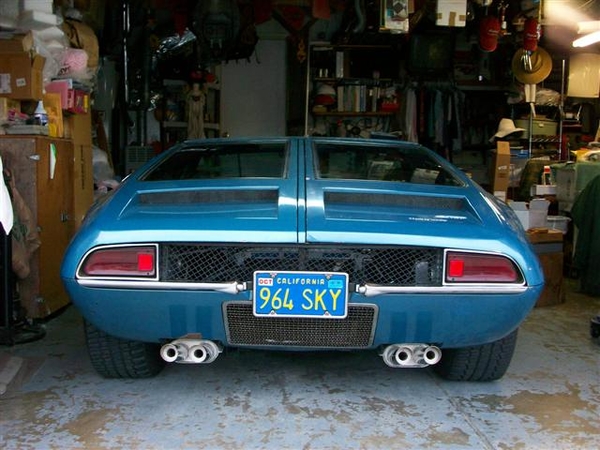
Ciao!
Steve

Well, only 4 more days before we head out to Reno and I think this one is pretty much wrapped up!
I installed my new oil pan and std volume pump (see dyno sheets in next post as to why!) Fully baffled and a 6qt capacity, not counting oil filter.
New Pan: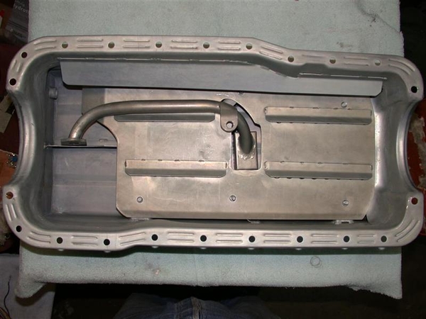
Bottom of pan. No skid plate required..read on.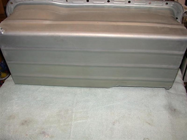
Front of pan: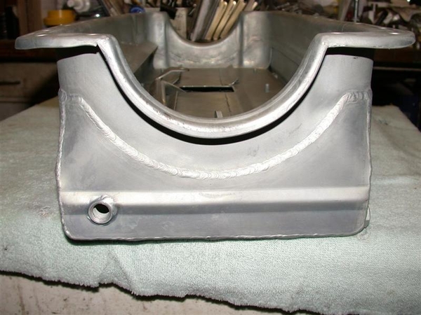
Note fitting for oil temp sender and a front drain. There is also a rear drain fitting on the other side under the starter.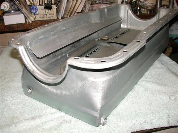
Windage tray details: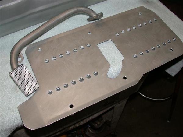
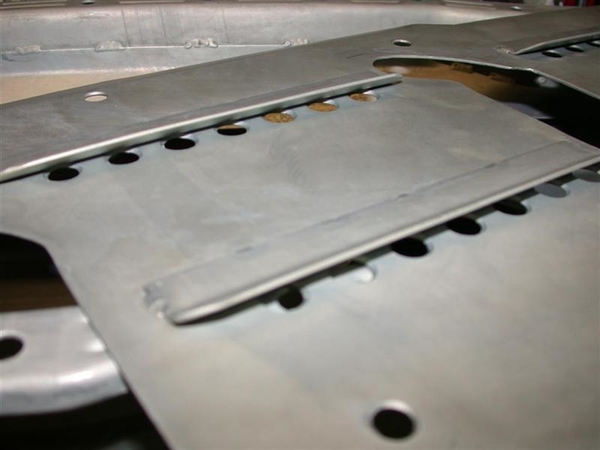
Here is how the volume stacks up when I filled it up with various amounts of water...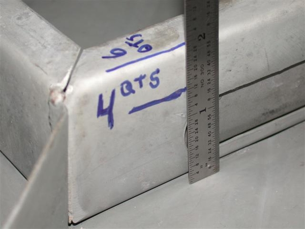
On to the installation!
First the new std volume pump!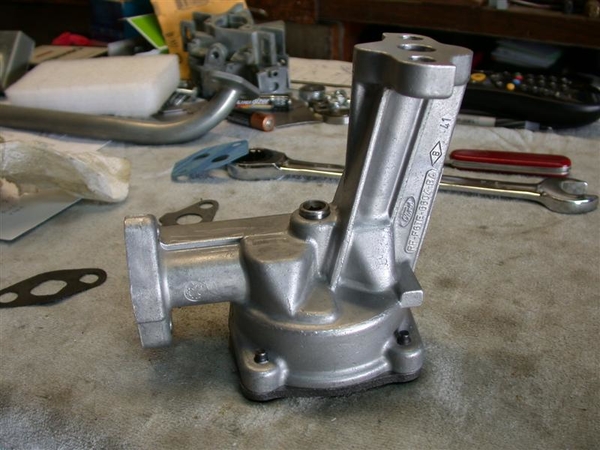
Installed with new pickup.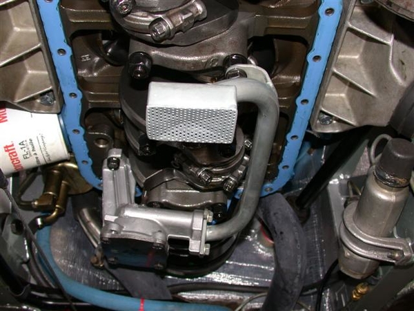
Checking clearance for pump and dipstick to the windage tray. No probs!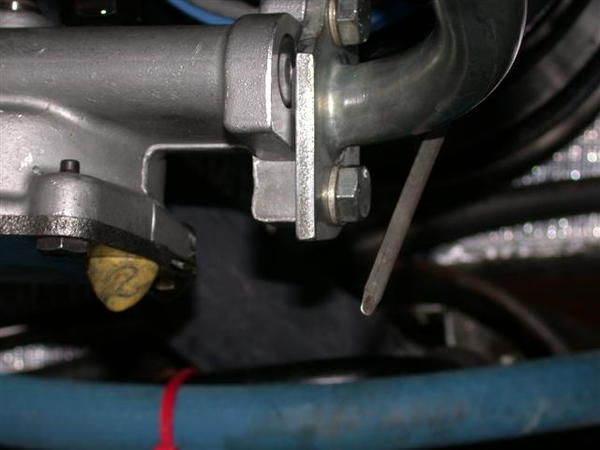
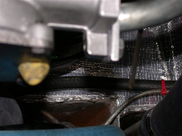
Also checking pickup clearance to bottom of pan: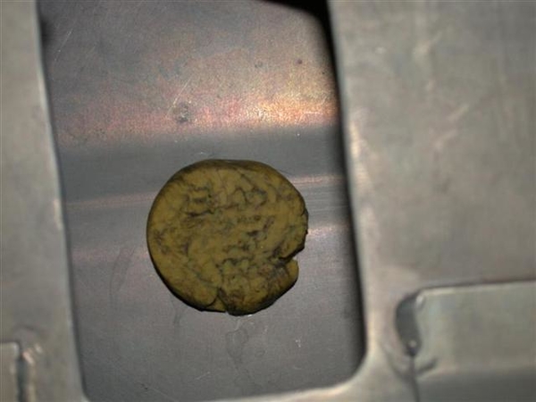
At least 1/4" of clearance should be fine!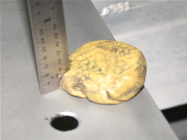
I filled and remarked the dipstick to give me a 5qt mark and a 6qt mark for full.
Underside clearance....after all, that was why I went through all of this!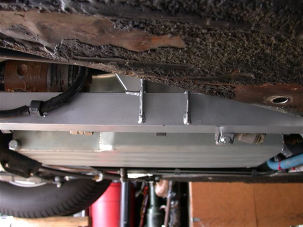
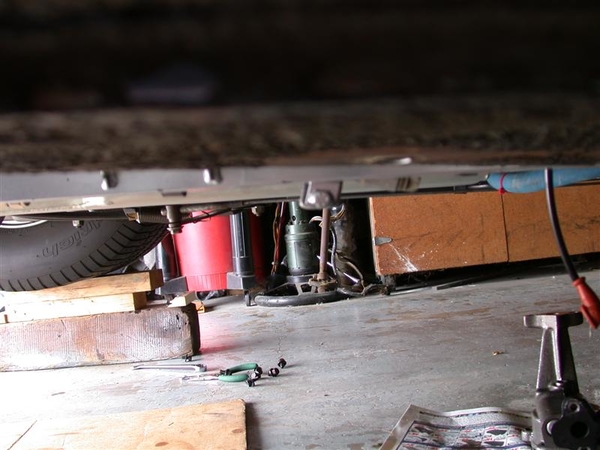
Other than the bellhousing, these are the lowest pieces on my chassis, and you can see that at least the bracket has been "touched" a few times by the tarmac or perhaps driveways!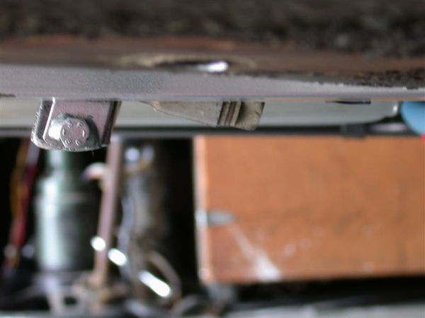
Here is as good a shot as I could get for showing the relationship of the frame rails and the bottom of the oil pan!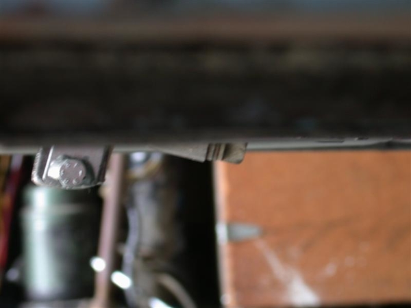
I reused my silicon gasket that had only 800 miles or so on it. I was getting a little leakage out the front seal area, so a day or so later, I loosened all the bolts up, shifted the gasket around a bit, tightened it all back up and so far so good.


DYNO RUN RESULTS!
Now we're not talking any top fuel results out of a small block here. My goals were simple....make "good" reliable street horsepower and torque, and have and engine that may last 60K or more miles...of romping through the hills and dales of the neighborhood!
Limit was about 6000 rpm's for the purposes of this build and my comfort level of spinning jack-shaft components! You can see where the cam and intake run out at about where they should. NO optimization of max spark advance was done here on this thrash....this was only to get mixture set properly.
Here is why I had to change to the standard volume oil pump. About 5500 rpm's the valves started to float.... Note the mixture at the bottom of the chart shows a RICH mixture...not even on the charts yet! This was last year when I got the car running again, August I believe. Maybe late July.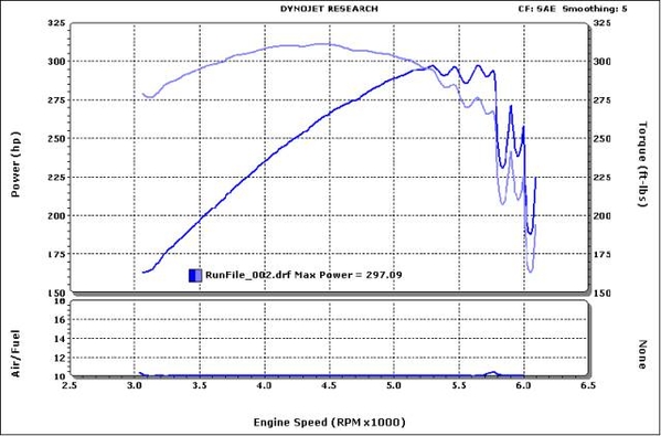
Fast forward, to new STD VOL oil pump, and last weekend! Note no more breakup at 5500. Mixture magically has not changed yet... LH side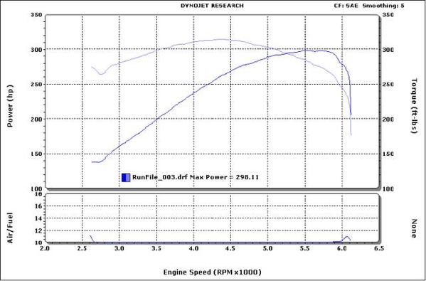
After leaning out the secondary jets from a 68 down to a 65, and reducing the primaries from a 64 to a 59, we obtained the best results! Best torque and HP of 320+ ft-lbs/ 309HP. Nice broad torque curve peaking at about 4500rpms. First we did secondaries and noticed a big change. Then the secondaries and obtained the final numbers as follows.
RH side of engine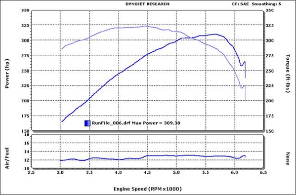
What we finally ended up with, for some reason, was the LH side of the engine being a tad more rich than the RH side. To cure this, we had to "cross jet" the carb, or make the jets different on each corner of the carb.
What I did, was increase the RH primary jet size from a 59 to a 64 (all we had for jets!) and go from a 65 to a 66 on the RH secondary.
This served to make the RH results more rich, closer to the LH results. We did not go back and recheck the LH side.....
We lost a couple of HP, but that could have been anything...me on the pedal....but the results are 1) much better fuel utilization, should be better on gas! 2) confirmation of a good solid street motor for the GOose!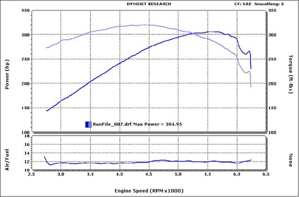
If you figure that the ZF can rob up to 25% of horsepower from an engine due to rotational mass etc, that would put this little 302 stroker (331CI!) at somewhere near the 400HP mark at the crank! Driving results back this up....as it is an absolute kick in the shorts to roll on the throttle and feel the secondary circuits kick in....and push you back in the seat!
It has been a tough project with no shortage of obstacles and challenges! In the end, definitely worthwhile!
Now, to get that ZF linkage adjusted properly! When I lifted the front of the engine a hair to make the oil pan and air cleaner fit optimally, it changed the relationship of the trans linkage....again! It's always something....
EDIT 040620: Again, ZF shifter issue was my mis-adjustment of the shifter rod support trunion such that the shaft touched the firewall shifter shaft tube in 2 & 4! Once I put the trunion back where it was....all was good!
Ciao!
Steve


NOT AGAIN!!!
Would you believe that on the way home from Reno, we hit a HUGE pavement transition (STUPID CALTRANS didn't put up any BUMP SIGNS!!!!) and seemingly bottomed the car on all 4 corners!
Once I got home and started looking around.... I found a crack on the passenger side shock tower now!!! Not as bad as what I started with on the driver's side...but a crack! It would appear that the addition of the two extra bosses on the ladder bar (shock to shock support bar) did it's job!
So, I get to take it all apart again. Now, before you feel sorry for me for this.....you also need to understand that after a short side trip on the way home to see family out in the valley, they called after we were out on the road to tell me that I "left a good oil puddle"..... This was pre-bump!
Apparently, my trans front seal took to leaking somewhere along the trip.... along with noticeable spooge emanating from the bellhousing, which ended up all over the RH side of the chassis... which is how I found the aforementioned crack.... Now it leaves a good tablespoon of 80/90W every time you park it...
So, I think this explains why second gear took to grabbing on me.....all of a sudden. I think the clutch disc is grabbing because it is oily....which, since it is Kevlar, I can simply soak in parts cleaner and reinstall......
EDIT 040620: I eventually pulled the ZF to take the engine apart for the bad crank journal finish, and I believe at that time I took the ZF apart and replaced the front seal, as well as a synchro ring or two and the front needle bearing in the case. Also stopped filling it so darn full of oil! Also stopped using a friction modifier (for posi units!) as I think that's what got on the clutch and caused it to slip. Other posts covered these bits....... End Edit
But wait! There's more!
Also trans related....my 4th gear just isn't happy. It was always a little funny feeling....but it would work. This time, after changing the rear gear oil before the trip, it now jumps out of gear very easily. It just doesn't feel like the lever is moving far enough that the gear is engaged fully. I suspect something in the synchronizer assy is amiss, and is not allowing the sliding hub to move fully onto 4th gear.
EDIT 040620: This 4th gear issue was self induced as I have mentioned elsewhere in other corrections. Shifter shaft support trunion adjusted improperly! Transmission was fine! End edit.
Trans needs to come out.
OK great! BUT WAIT!!! THERE IS STILL MORE!!!
When I built my 331 stroker on the 5.0L block some 3-4 years ago, there was a problem with some of the crankshaft finishing of the units in circulation, namely in the thrust bearing surface of the #3 main bearing in the block. The rumor mill would have you believe that as crank blanks were distributed to various shops for final finishing, that a shop, or multiple...didn't do such a great job of finishing the surface on the #3 thrust bearing!
(I feel pretty good that I got 800-1400 miles out of my car so far! Some have never made it out of the shop before excessive movement was noted and required replacing!)
We had checked this out during the dyno run and noticed some movement.... Later, I found my build sheet spec's from assembly, and I had noted that I measured .005" of freeplay, or movement fore/aft of the crankshaft. The "some movement" was definitely more than .005" which is about the thickness of a thick sheet of paper, or two thin ones!
Being the "damn the torpedoes" sort of character that I am, I was going to Reno, even if I had to come home on a tow truck! The car had already made 800 miles and a long blast into the Valley (Sacramento Area) last year on it's maiden voyage of sorts.....
We made the trip just fine and got at least 20MPG on the way home to boot!
When I changed the oil pan, I had found particles of metal, copper colored that stuck to a magnet.... in the old oil pan. I know I cleaned the oil pan out before I installed it....as I am particularly anal that way..... so I know these bits came from the inside of my new motor!
Finally, last month, before the PCNC meeting, I put the car up on stands and got underneath it with some precision measuring tools and determined that I had between .015" and .019" of fore-aft movement in the crank now.
While it isn't dramatically increasing, this is bad, and will need to be dealt with!!!! The fix is to pull the crank, have this one area (or whatever offending area I find) re-polished to a finer surface, and install it with a new thrust bearing.
SOOOOO!!!!
1) I pull the trans.
2) Pull the motor.
3) Send out the crank
4) Fix the shock tower crack and repaint...
5) Pop the trans open and see what the hell is going on with 4th gear. Second probably needs a new blocking ring as well... May also put in the ring gear bolts with the safety wire provisions.
6) Reassemble motor and install
7) Reinstall trans!
8) Drive the car with no further issues....from the drivetrain....
Should be a piece of cake!!!!
Why you ask?
BECAUSE EVERYTHING THAT CAME OUT WILL GO BACK IN WITH NO FURTHER MODIFICATION!!!! Or at least that is what I keep telling myself...."it was in there before, it should go back in just fine!" No milling machine, metal lathe, machine shop, BFHammer, or trips to Fastenal will be required!
Keep drinking the kool-aid.....!
Have a great week!! Get out and drive your cars!!!! I'll take the car out one last time to the PCNC meeting tomorrow nite, and then I believe it is time to bust it apart again! Goal is to be back together for a Sept 23rd run up to a car show in Murphy CA!!!
We'll see!
Steve
PS: I will not be documenting any of this portion of this adventure on this post....but if you have any questions or concerns, please ask!
OK, here we are mid-damnpendic....what better time to go back and fix this old post! Comcast trashed all my pic's when they decided not to do picture hosting several years back......and I've been WAY toooo busy to do this!
Well, I am glad I waited! Old website would have only allowed me to put attachments on the text, not necessarily "in" the text......but this new site allowed me to simply copy a pic, and paste it in the old web address for the same picture! Voila! SO, spent most of yesterday reposting pic's and updating things here and there..., it was raining pretty good here and I had promised myself to take advantage of a rainy day to do this, so I did!
My original intention was to get other owners with "stagnant" projects inspired to get out into their garage and tackle their Goose "obstructions" to getting their cars back on the road! I know that it helped a few guys at the time as I got great feedback. Another web board post for a different marque inspired me to do this, as what they had done.....inspired me to take the jump and just do it! Of course the fact that I had busted a shock mount AND I had a fresh engine waiting in the wings helped a bit too!!!
I had fun going back and reading thru all the BS I wrote and the issues I fought with. Musta been crazy.....but it was CRAZY GOOD when all done!!!! Miss that car a heap!
Enjoy again!
Steve
Sending a sincere thank you! I went ahead and archived the text and photos in case of another technical calamity. And yes, it is certainly inspirational. Do you know the car's whereabouts today? Thanks again.
")

