

the work looks great! It should be ready for some serious track laps in TX
question, when you tighten the bolts for the arm bushings, do you have the arms at ride height as not to add the torsional springiness of the rubber twisting?
That's what I did.
I set the car on my original shocks, and then I tightened the bushings.
Rocky.
Still a little work to do yet, but it's coming!
I set the car on my original shocks, and then I tightened the bushings.
Rocky.
Still a little work to do yet, but it's coming!
Hi Rocky,
Lookin great man. Very nicely detailed process steps. The camber lock modification is slick. I like it. Royalties should be paid to you or W-WadeCo?
Nice to hear you are getting sign offs accomplished. How soon do you think for the air tools...those are the fun ones..
Hey..what are you using for rotors/pads?
Hey Rob -
Getting signed off on air tools is a long, ardouous journey. I have to pass bench grinder certification first.*
I did kind of jump the gun by using my angle grinder to fit the shocks (the Koni 30s "hats" can interfere with the shock brackets at full droop) a little prematurely.
With regard to rotors -
I am using vented 12.xx" (number to be filled in later) mustang rotors.
With regard to brake pads -
Stock calipers with Porterfield R4S (Street Compound).
With regards to rear brakes -
This will drive most everyone who has a dog in the fight nuts, but.....
I am using the 1980's technique of dual, stock rear calipers. Since the rear uprights are "unisex", I just have 2 sets of calipers on each rear wheel. This is a common technique from the past, made obsolete by the relatively low cost Willwood kits available at several suppliers.
I can lock up my rears any time I want, I keep my stock emergency brake configuration, and the price was right.
4x $2.00 Bolts
8x Brake pads
2x $15 Braided steel brake hoses
$100 in rebuild kits for 4x calipers
Royalty checks should be submitted direct to W- WadeCo, care of me.... PM me and Ill send you the address!
Rocky
* Note - I am teasing my friend and mentor (Wade) about all this. I am sure he would be perfectly willing to let me take the next step -when ever I want to grab the MIG welder... have at it! (....but I don't think the results would be what either of us want to show off!)
quote:Nice to hear you are getting sign offs accomplished. How soon do you think for the air tools...those are the fun ones..
Getting signed off on air tools is a long, ardouous journey. I have to pass bench grinder certification first.*
I did kind of jump the gun by using my angle grinder to fit the shocks (the Koni 30s "hats" can interfere with the shock brackets at full droop) a little prematurely.
With regard to rotors -
I am using vented 12.xx" (number to be filled in later) mustang rotors.
With regard to brake pads -
Stock calipers with Porterfield R4S (Street Compound).
With regards to rear brakes -
This will drive most everyone who has a dog in the fight nuts, but.....
I am using the 1980's technique of dual, stock rear calipers. Since the rear uprights are "unisex", I just have 2 sets of calipers on each rear wheel. This is a common technique from the past, made obsolete by the relatively low cost Willwood kits available at several suppliers.
I can lock up my rears any time I want, I keep my stock emergency brake configuration, and the price was right.
quote:The camber lock modification is slick. I like it. Royalties should be paid to you or W-WadeCo?
Royalty checks should be submitted direct to W- WadeCo, care of me.... PM me and Ill send you the address!
Rocky
* Note - I am teasing my friend and mentor (Wade) about all this. I am sure he would be perfectly willing to let me take the next step -when ever I want to grab the MIG welder... have at it! (....but I don't think the results would be what either of us want to show off!)
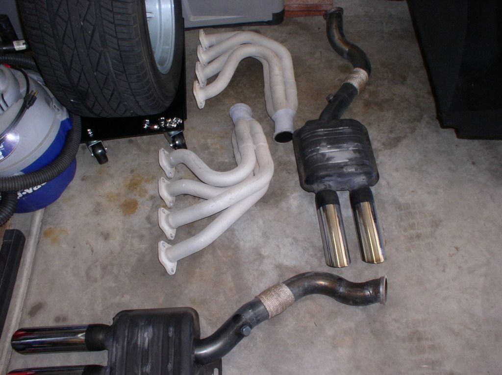
Got my Front Suspension pretty much buttoned up. You can see the pictures in the slideshow here. Things remaining:
1. Brake Hose Routing
2. Bleed Front Brakes
3. Bed Front Pads (Porterfield R4S)
4. "Home Align"
5. Professional Align (Set Up Car / Set Final Ride Height)
So my project got delayed a bit by a "difficult to install" front passenger rotor. The bearing had run hot at one time, and the spindle was just slightly damaged - it had a little ridge on the outside, and then on the inside it was just a tiny bit undersized.
I struggled with that for a week until I got that one figured out, and understood how to get the inner bearing race set on the spindle. Now it is set, and all is buttoned up.
Enjoy the pictures.
Suspension Upgrade - Final Pix
Thanks again to Wade (MarkIV/4280) for the precision work:
1. Setup of the Bearings in the Rotors
2. Pressing Out / Reinstall Bushings
3. W-WadeCo Camber Lock Kit
4. Caster Modification to Ball Joints
5. Specialty Tools
6. Expert Advice
Rocky
Next Project - High Torque Gear Reduction Starter....
So I had been having some minor "Hot Cranking" issues (it is not unusual to be hot here in Tucson BTW!). So a PMGR Starter would seem to be a good upgrade.
The worst part of working on the starter is access. My first problem was that the studs in the bell housing were too short, and then that I couldn't get them out!
But using a very super duper, and nearly magical tool, a few turns of the ratchet had them out in minutes.
Pretty amazing.
Rocky
When I have more time, I will add more detail on the (COMPLETED) PMGR starter project. I have started my car, and the thing cranks way better than my old Motorcraft starter.
Attachments
Images (1)
_(Medium)")
_(Medium)")
Sounds like some good progress Rocky.
Gotta share the details of the very super duper tool in action for us. ;-)
Gotta share the details of the very super duper tool in action for us. ;-)
quote:Originally posted by Rob Borruso:...
Gotta share the details of the very super duper tool in action for us. ;-)
Yea, I don't reconize those pieces.
the work looks great, hope it will be great on the road & track also
I can tell the interest is boiling over... So I will tell all.
I borrowed two tools to attack these recalcitrant studs (remind you of anyone????)
Anyway - the first is a Proto 4515 Stud Remover. This is the tool I used efficatiously.
It is basically a large, heavy rounded deep-well socket-like contraption. It has a 1/2" drive on one end. The offset hole bored in the side accepts a wedge with a very aggressive rasp-like surface.
Judicious application of the wedge, and torque on the drive digs the hardened teeth into the stud. The wedge shape is pulled ever tighter into the stud as torque is applied. Obviously, you want to set it up to apply the torque in the direction you need for the stud to turn.
Rocky
PS> One guess as to who loaned me this awesome tool....
Attachments
Images (1)
")
The second tool I had access to is the old "Matco SR-19". This baby has an eccentric knurled wheel on the opposite end of a 1/2" Drive.
It operates basically on the same principle, the drive torque forces the knurled wheel into the stud, locking it into the grip of the tool. Additional twisting force rotates the stud out of the threaded hole (be it the block, bellhousing, etc.).
Rocky
PS> Of course - it was Wade (MarkIV/4280).
"The Right Tool for the Job"
Attachments
Images (1)
")
")

That was my first approach. Maybe I didn't get my two nuts tight enough, but when I did try that, they both twisted on the shaft (even thought I was torqueing the inner one).
I was never able to really get a good wrench on the inner nut due to the closeness to the block / header / frame rails.
It's tight in there! I was happy to have access to the right tools.
I was never able to really get a good wrench on the inner nut due to the closeness to the block / header / frame rails.
It's tight in there! I was happy to have access to the right tools.
I like the "looks" of the Proto 4515. I had never seen one and from google it looks like if I do, it will be used.
how has the new starter worked?
how has the new starter worked?
quote:How has the new starter worked?
It works good. Good cranking action - my engine is running again. My first drive after the suspension work is this weekend. I guess I forgot to post up more pictures.
Funny (well, not so funny at the time) anecdote about my car....
When I drove to Yuma for MATO (3 Hrs.), I noted a new vibration at speed. I had just replaced my tires, and had the new ones mounted and balanced. This was my first ride on these tires, and I had not messed with my suspension, so I suspected a balance issue.
I took the rear tires and wheels to a different shop. He only had the kind of machine that had to put a spindle through the center of the wheel. We had to get the De Tomaso caps off.
"Oh, I just whack 'em with hammer", the guy said...
"Hell No you don't just 'whack 'em with a hammer'"!!!!
Anyway - we spun up the wheels, and one was off by 1.75 oz., and the other by .5 oz. I think I found my problem.
Don't ever get your wheels mounted and balanced at C***** **********, even of they do have a nice Factory Five Cobra replica on the shop floor!
Anyway - All is well now. The car just got dropped off for alignment after the front suspension rebuild.
Rocky
PS> I think I owe JFB a picture of my PMGR starter install...
Attachments
Images (1)
_(Medium)")
Is it possible to connect the red wire to the thik black wire from the starter?
To keep the original starter relais working?
no need for an extra wiring .
Simon
To keep the original starter relais working?
no need for an extra wiring .
Simon
Simon - I tried this (it was my first approach).
Originally, I just ran a jumper from the main power feed to the little solenoid terminal.
It was very quick and easy.
Unfortunately, I found about 50% of the time, my starter would "run on", and keep spinning / remain engaged for 1-2 seconds after the key was released.
"forestg" posted up the solution, which is the same as what is provided (upon request) with the DB starter...
The main feed goes to the INPUT of the bulkhead mounted solenoid (direct to the battery).
The solenoid on the PMGR starter goes to the OUTPUT of the bulkhead mounted solenoid.
Works great, lasts a long time (I hope).
Rocky
")
[QUOTE]Originally posted by Rocky:
Simon - I tried this (it was my first approach).
It was very quick and easy.
Unfortunately, I found about 50% of the time, my starter would "run on", and keep spinning / remain engaged for 1-2 seconds after the key was released.
Thanks , that was also what my starter is doing, I go chance the wiring as you discribed.
regards
Simon
Simon - I tried this (it was my first approach).
It was very quick and easy.
Unfortunately, I found about 50% of the time, my starter would "run on", and keep spinning / remain engaged for 1-2 seconds after the key was released.
Thanks , that was also what my starter is doing, I go chance the wiring as you discribed.
regards
Simon
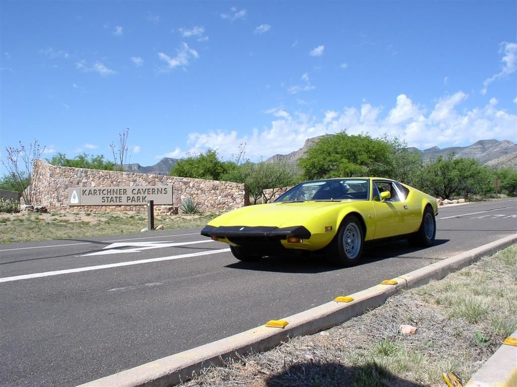
Shakedown Cruise on #5357 - Getting Ready for the Fun Rally! (I'm Driving from Tucson To Houston).
OK - So it was just me that went on the run! That's not my fault! I tried!
So having just completed a series of updates to my car, I wanted to "wring it out" under real-world conditions. The updates were:
* Complete Front Suspension Workover
* 8" Wide Front Tires & Brake Hose Routing
* New Porterfield R4S Front Brake Pads
* Rebalanced Rear Tires / New Rubber
* PMGR Starter
I also had the opportunity to run a Air/Fuel Meter and log some data.
Overall - everything went GREAT. I put about 130 miles on the car, simulating conditions I will encounter. No problems with any of the upgrades, or anything else.
Now to scrape the bugs off, and do the very final prep work before we leave on 13 May.
Here's some pictures from the ride.....
Slideshow from "Shakedown Cruise"
Rocky

Any Armchair tuning analysts (or experts) out there? Any comments on these graphs?
I am struggling a bit with this LogWorks Software (Scaling and Selecting Axis'). Anyway, here's a couple of representative files, with my assessment.
The last set is an acceleration from a rolling start onto the freeway - to about 75 mph. Bottom is time in seconds, and the left axis is A/F Ratio.
Personally, I think my carb adjustment is good based on "seat of the pants" performance, plug inspection, lack of soot on the back of the car, and now this data (I've got a lot more files) but who knows what the experts among us can discern....
Here is a sample of the data I collected - I tried to get both sides of the engine, under similar conditions (but collected a day apart). The Idle & steady cruise are easy to match conditions, but acceleration is more subjective.
Warm Idle - Good Adjustment (might be a little rich at idle). Can be set to > 14.7 under a no-load condition without issue.
I would be fascinated to figure out with the 3 Hz oscillation in the Passenger Side correlates to.

2500 RPM in 4th Gear - Again, I think things are set pretty well. Running close to stoichiometric under a medium RPM, low-load condition.
Note, this carb does not have vacuum advance.

Acceleration (Driver Side was more "intense" than Passenger Side)
I believe things are OK. Upon acceleration, you expect the mixture to richen considerably, due to the Accelerator Pump, and the Power Valve Opening. I think when the ratio the drops down is when I am mashing the gas, and the peaks are as I let off the gas at shift points.

Trying to match up this data is why I need:
a) An RPM Sensor Input $30 (plus cable wiring time)
b) Another O2 Sensor $160
Thanks - Any comments on people's assessments of this data is appreciated.
Rocky
from http://pantera.infopop.cc/eve/...381053556#2381053556
quote:Originally posted by JFB #05177:
I aint no ex-spert...but a question and comment.
I think your ranges of A/f show and like you say it feels from the other indicates that you have a great tune.
the rich dip at 12 to 15 seconds, would that be a gear selection where you were below your cam and had a slight WOT bog?
Attachments
Images (1)

quote:rich dip at 12 to 15 seconds, would that be a gear selection where you were below
JFB - Thanks for looking at this.
I assume this is accelerator pump & Power Valve action. I would love to have an RPM Sensor with this data as well.
One thing that I just learned is how "dynamic" this data is... if you just read the info, without really plotting this stuff, you just think "oh well, it should be at 14.7, right? It's a no brainer!"
It is interesting to see the trends, and the effects of various condition (Idle, Decel, WOT) on the ratio, but this data really doesn't tell a tuner what to do (yet).
Thanks for the annotation.
as for the RS "3 hz"; counting peaks for the 16 second sample I get 2.1 hertz if that is what you are observing.
are you having to physically remove the O2 sensor from one exhuast and move it to the other?
are the locations about the same distance from muffler.
what is your idle rpm
normally the first thing I do when trying to determine the cause for similair "noiz" is to look very closely at instrumentaion to besure I don't chase something that is not there. that would include knowing how the instrument samples and displays
Not sure if your pump gas is an ethanol mix like we have in MA, this effects the mixture ratio. http://www.hotrod.com/how-to/e...eband-oxygen-sensor/
Thanks, Brian.
JFB - Yes, right now, I have access to a "Two Channel" monitor unit, but only have a single sensor, and a single cable.
So the runs were made on alternate days, attempting to duplicate each other. I have to physically move the sensor from one exhaust to the other.
Idle is easy, maintaining a steady RPM on the same stretch of road is pretty do-able. Matching shift points and gas pedal modulation on an acceleration to 70 MPH is impossible.
I agree, I have to read more, and get more familiar with the characteristics of the instrumentation.
Rocky
")
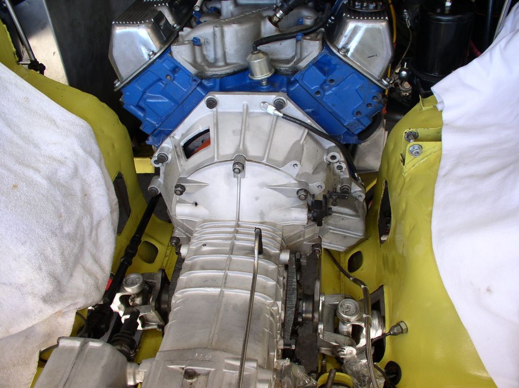
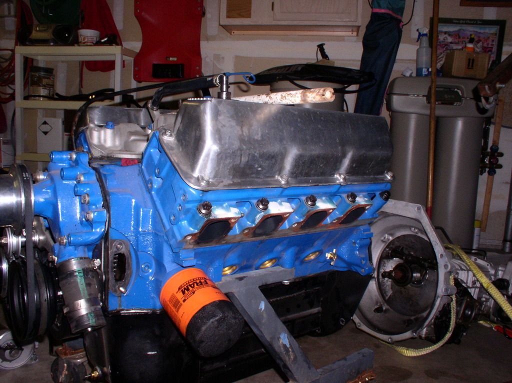
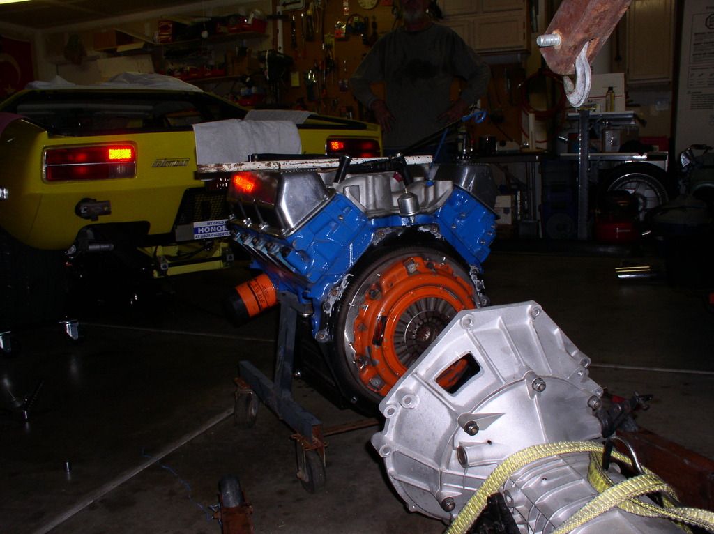
Had a little minor problem with my motor, and wanted to clean up the bay a little.
So out she comes.
I expect I will be working on the transaxle as well. Getting an occasional "crunch" if I'm not careful when I shift into second gear.
Thanks to Wade (MarkIV/4280) for help on the actual motor pull. We had it out of the car in 45 minutes.
Rocky
So out she comes.
I expect I will be working on the transaxle as well. Getting an occasional "crunch" if I'm not careful when I shift into second gear.
Thanks to Wade (MarkIV/4280) for help on the actual motor pull. We had it out of the car in 45 minutes.
Rocky


So what do you do if you have a major problem???? 
I guess that's when the "Frame Off" restoration begins!
Rocky
Rocky
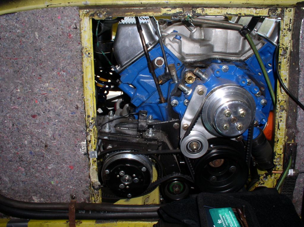
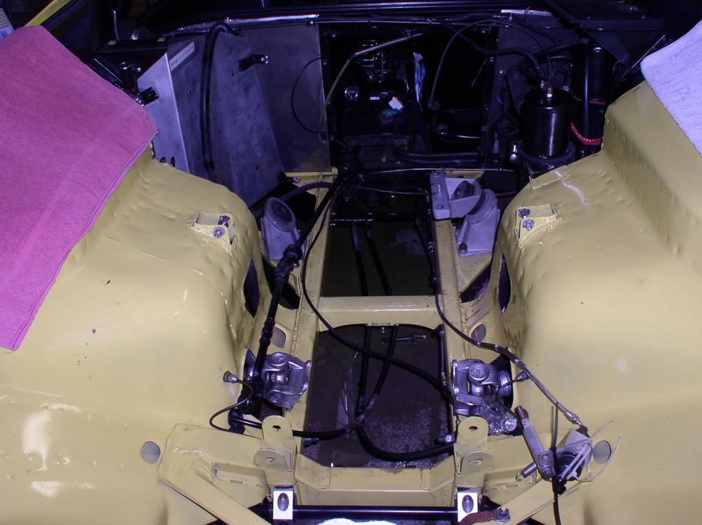
Is the altenator mounted besides the A/C pump?
Simon
Simon
Yes it is. The alternator is actually behind the permanent bulkhead when the engine is in the car.
The engine pictures (out of the car) have the alternator removed - to make it easier to get the motor out of the car.
You can see better pictures of the setup here, and on the top of page 7....
Rocky
Scroll to the bottom for the Sanden / Alternator Pix
The engine pictures (out of the car) have the alternator removed - to make it easier to get the motor out of the car.
You can see better pictures of the setup here, and on the top of page 7....
Rocky
Scroll to the bottom for the Sanden / Alternator Pix
good idee,
simon
simon
any findings on the engine noise?
Still working on that one....
Engine is at the machine shop, awaiting forensic analysis.
We (MarkIV/4280) began my transaxle refresh efforts. In Wade's words.... "We are now ZF Mechanics!".
Yesterday (09-23-2014) was the initial teardown. Wade is building a fixture today to hold the gear stacks.
Per direction of Lloyd Butfoy (RBT Transmisison), the fixture requires 52mm and 79mm rings, with 80 mm center to center spacing. Pictures of the fabricated fixture are coming soon.
Anyway, Wade and I disassembled the case without problem. the 5th, 4th and 3rd syncro dog teeth look clean and sharp. All looks good at the high level. More details to follow.
Here is a slideshow of the pictures, and a glamour shot.
Initial ZF Teardown and Refurb.
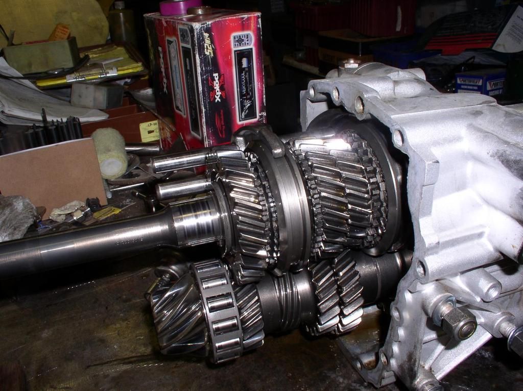
Rocky
So my 351C engine got torn down yesterday,
I spun the #4 rod bearing. The crank journal is toasted, but the rod and piston is OK. The rod end was checked, and it’s still good and circular.
Generally, everything looks like it’s in pretty good shape inside, with the exception of the one rod bearing. Lots more disassembly, flushing and evaluation still needed. I need to find out if I need a new oil pump (that’s a pretty minor expense).
I have a crank that I am bringing over to the shop tomorrow, I’ll hope to get some pictures. Lots of parts on their way….
Everything needs to be disassembled, checked, and the crank machined and balanced.
I still would sure like to know what caused the problem – spinning it over 6200 RPM a couple of times shouldn’t kill a bearing like that…..
Rocky
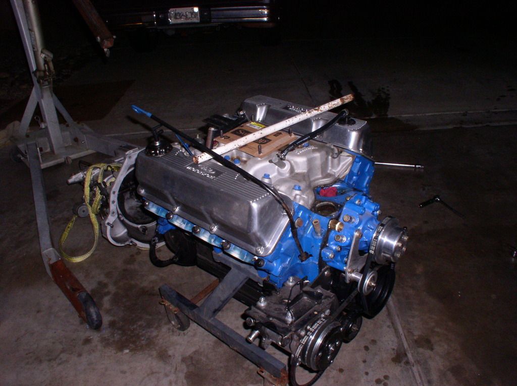
New (to me) ported heads getting ready for machining. These are D1AE GA heads - with the 66cc chambers.
They will get:
Minor hole drilling for water flow
Hardened valve seats
Valve Guides
Pedestals machined for roller valve train
Painted
I'll post up some flow numbers as soon as I get them.
The motor is slowly coming back together. Bottom end is nearly ready for assembly with new flat top pistons, newly machined crank, hardened race bearings, and all other previously installed oiling mods.
They will get:
I'll post up some flow numbers as soon as I get them.
The motor is slowly coming back together. Bottom end is nearly ready for assembly with new flat top pistons, newly machined crank, hardened race bearings, and all other previously installed oiling mods.
Attachments
Images (1)
_(Medium)")
Add Reply
Sign In To Reply